
Call Us
+86 136 6007 9809
Call Us
+86 136 6007 9809

Sep. 21, 2026
Electric vehicle architecture places increasingly complex power electronics, control systems,
thermal-management components and electrical distribution hardware into compact, lightweight packages.
Inverters, on-board chargers, power distribution units, auxiliary electronic modules and other EV subsystems often require removable covers,
brackets and service panels that must be assembled efficiently while operating within demanding mechanical and environmental conditions.
Where the threaded attachment point is located near an accessible sheet-metal edge or flange, EV clip-on nuts can provide a practical mechanical fastening solution.
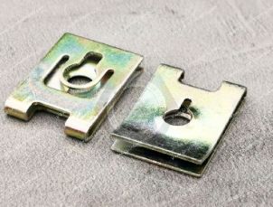
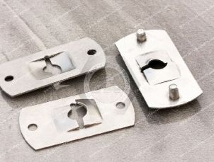
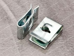
These edge-mounted spring fasteners—including U-nuts, J-nuts, low-profile clip nuts and enclosed-thread clip configurations—can establish threaded attachment points without welding or tapping the sheet itself.
However, selecting a clip-on nut for an EV enclosure requires more than matching an M5 or M6 thread.
Engineers must evaluate the complete interface:
Clip Nut + Finished Panel + Edge Geometry + Mating Screw + Joint Stack + Environment + Assembly Process
For lightweight EV equipment, additional questions arise when steel spring fasteners interface with aluminum structures, coated panels, thermally active electronics and sealed housings.
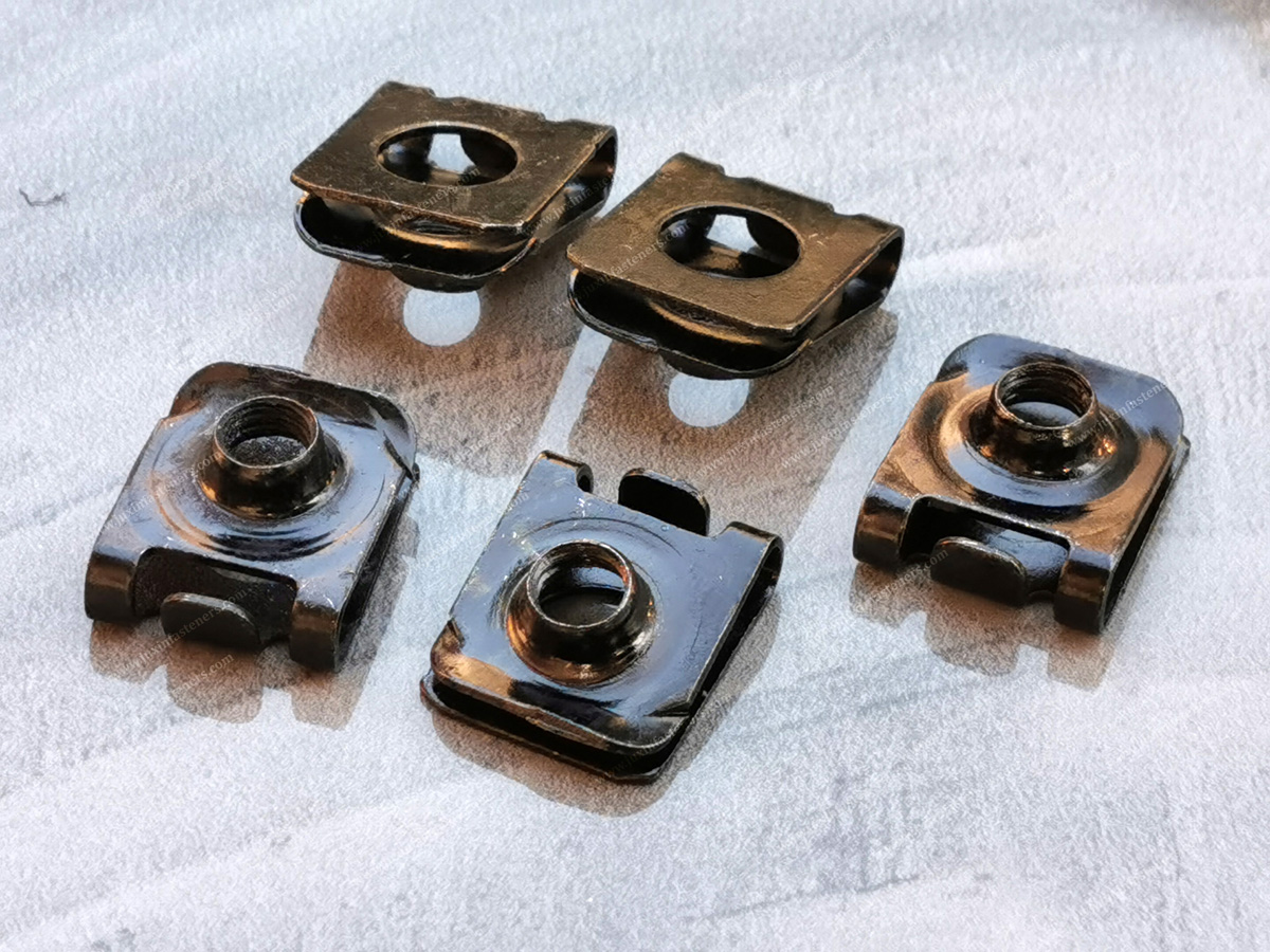
An EV clip-on nut is not a separate universal fastener standard created specifically for electric vehicles.
It is a clip-on or spring-nut architecture selected and validated for an appropriate EV application.
Depending on geometry, these components may include:
U-nuts;
J-nuts;
low-profile clip-on nuts;
enclosed hex clip-on nuts;
machine-screw spring nuts;
tapping-screw clips;
drawing-specific spring fasteners.
Their primary mechanical role is to provide or support a threaded fastening point at a suitable panel edge or flange.
Potential EV applications include appropriate:
inverter covers;
on-board charger housings;
power distribution unit covers;
auxiliary electrical enclosures;
electronic control-module brackets;
wiring-related brackets;
thermal-management equipment covers;
service-access panels;
lightweight protective covers;
auxiliary sheet-metal structures.
The suitability of a clip-on nut depends on the actual load path and vehicle program requirements.
Traction inverter systems contain sensitive power-electronic components within mechanically and thermally engineered housings.
Potential clip-on nut applications can include suitable:
secondary covers;
serviceable panels;
auxiliary brackets;
non-structural external sheet-metal features.
The clip should not automatically be assumed suitable for every inverter housing attachment.
Where a joint contributes to:
enclosure sealing;
structural integrity;
electrical bonding;
thermal interfaces;
high-voltage safety,
the complete subsystem requirements must control the fastening architecture.
On-board chargers can require removable covers and auxiliary attachment points.
Clip-on nuts may be useful where:
an accessible edge exists;
welding is unnecessary;
the panel geometry supports the clip;
serviceability is valuable;
the final joint can be validated.
The clip should be evaluated as one component within the complete OBC mechanical assembly.
Power distribution units and related electrical enclosures may contain:
covers;
brackets;
cable-management structures;
protective panels;
auxiliary sheet-metal features.
Clip-on nuts can provide removable threaded interfaces for suitable non-safety-critical mechanical attachments.
Electrical isolation, creepage, clearance, grounding and high-voltage requirements are separate engineering considerations.
Electric vehicles contain numerous:
controllers;
relay boxes;
communication modules;
sensor-related electronics;
low-voltage electrical systems.
Their support brackets and protective covers can create opportunities for edge-mounted spring fasteners where the mechanical architecture is suitable.
EV thermal-management systems can include:
pumps;
valves;
control units;
coolant-related modules;
heat-exchanger assemblies;
protective covers.
Clip-on nuts may be used on appropriate mechanical brackets or covers.
They should not automatically be treated as:
coolant seals;
pressure-retaining components;
fluid-system fasteners.
Serviceability is one of the clearest potential advantages of clip-on fastening.
Where a panel may require future removal, an accessible clip-on nut can provide a replaceable threaded attachment.
Potential applications include:
inspection covers;
protective shields;
electrical access covers;
auxiliary equipment panels.
This can reduce repair complexity compared with some permanently installed threaded systems.
EV lightweighting can involve combinations of:
aluminum sheet;
aluminum castings;
thin-gauge steel;
high-strength sheet;
polymers;
composite components;
mixed-material assemblies.
The fastener must therefore be selected according to the actual substrate rather than simply being labeled an “EV fastener.”
A spring clip interacting with aluminum does not behave exactly like the same clip interacting with steel.
Differences can include:
substrate hardness;
local bearing behavior;
edge deformation;
surface finish;
galvanic compatibility;
coefficient of thermal expansion.
The panel material should therefore be part of the clip specification.
Clip-on nuts can create threaded attachment points without applying a welding process at the clip location.
This can be attractive where engineers want to avoid introducing local welding heat into a lightweight panel.
However, it is too broad to state that welding always causes unacceptable distortion.
Actual distortion depends on:
material;
thickness;
joint geometry;
welding process;
heat input;
fixture design;
production control.
Therefore:
Clip-On Nut = No-Weld Option
but not:
Welding = Automatically Unacceptable
A clip-on nut may be considered when:
the thread is near an accessible edge;
removability is useful;
welding is unnecessary;
post-finish installation is advantageous;
the joint requirements fit the clip architecture.
A weld nut may remain appropriate where:
the manufacturing process supports welding;
a welded threaded attachment is required;
the material combination is suitable;
the design and validation support it.
For a broader technology comparison, see Sheet-Metal Fastener Selection: Clip-On vs Weld, Clinch & Rivet Nuts.
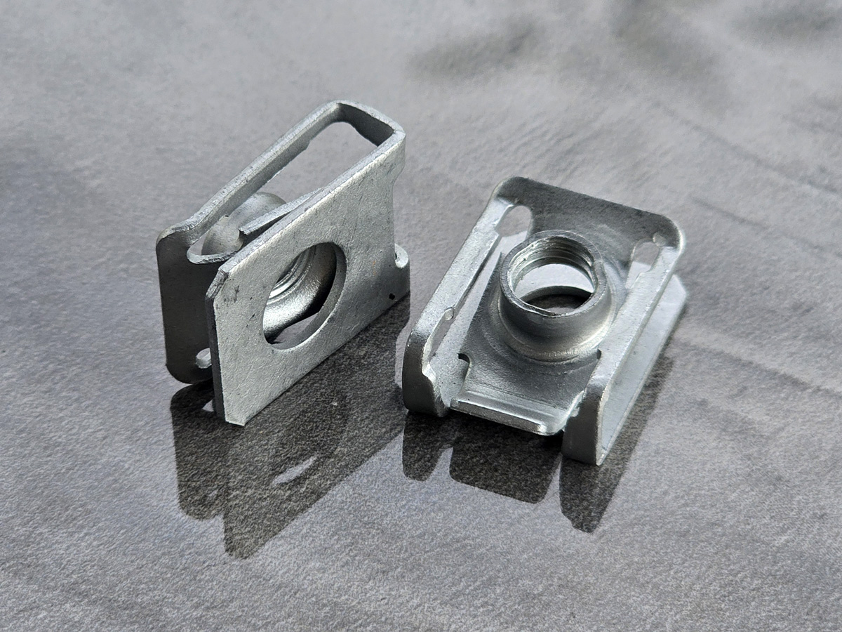
Clip-on nuts are sometimes described as supporting blind assembly because the operator may not need to hold a conventional nut behind the panel during final screw installation.
However, the clip generally still requires access to an appropriate panel edge during installation.
A blind rivet nut solves a different problem: it can be installed through a prepared hole from one accessible side.
Therefore:
No Backside Nut Handling ≠ Universal Blind-Hole Capability
Clip-on nuts rely on controlled interaction with the panel.
Relevant variables include:
base material thickness;
thickness tolerance;
paint;
e-coat;
plating;
conversion coating;
other surface layers;
local forming;
stacked material where applicable.
The clip therefore sees the finished panel interface, not merely the nominal CAD sheet thickness.
For detailed selection guidance, see Panel Thickness Selection Guide.
Suppose an enclosure drawing specifies an aluminum or steel sheet at a nominal thickness.
After finishing, the interface can include additional surface layers.
For a clip operating near its grip-range boundary, this may affect:
installation force;
retention;
spring deflection;
surface marking;
alignment.
Therefore:
Nominal Sheet Thickness → Starting Point
Finished Interface → Actual Clip Selection Input
This distinction remains fundamental in EV enclosure design.
Describes how effectively the clip remains attached to the panel before and during final assembly.
Depends on the complete:
Screw + Clip Nut + Panel + Cover / Bracket
system.
Relevant factors include:
thread engagement;
tightening process;
panel stiffness;
joint stack;
screw specification;
service loads.
Therefore:
High Clip Retention ≠ Automatically High Joint Capacity
Not automatically.
The spring force used to grip the panel primarily supports clip retention.
It should not automatically be interpreted as a prevailing-torque locking mechanism acting on the screw.
Resistance to screw loosening depends on the complete threaded joint.
Relevant factors can include:
initial clamp;
friction;
transverse movement;
vibration;
thermal cycling;
joint stiffness;
locking feature where required.
Therefore:
Panel Grip Spring Force ≠ Screw-Locking Torque
EV assemblies can experience mechanical excitation from:
road input;
tires and suspension;
electric drive systems;
pumps;
compressors;
fans;
structural movement.
The absence of a conventional internal-combustion engine does not mean the vehicle is vibration-free.
Clip-on fastener selection should therefore consider the actual vehicle subsystem and load environment.
A spring clip can remain securely attached to the panel and still be part of a threaded joint that loosens if the joint is poorly designed.
Likewise, a correctly designed screw joint can remain stable even though the clip's primary purpose is simply to locate the threaded attachment.
Therefore:
Clip Retention Test ≠ Joint Vibration Test
For more detail, see Strong-Grip Clip-On Nuts for Vibration-Resistant Assemblies.
Power electronics generate heat during operation.
Vehicle systems can also experience changing ambient temperatures.
As temperatures change, materials expand and contract.
This can affect:
enclosure dimensions;
joint stack;
gasket compression;
hole alignment;
fastener loads;
contact interfaces.
The importance of these effects depends on the actual material combination and geometry.
Aluminum alloys generally have a higher coefficient of thermal expansion than steels.
In a mixed aluminum-steel assembly, temperature changes can therefore create relative dimensional movement.
However, the presence of a clip-on nut does not automatically solve differential thermal expansion.
The complete joint should be evaluated for:
geometry;
temperature range;
joint length;
clearance;
constraint;
screw preload;
material combination.
Some clip-on fasteners provide limited positional accommodation.
This can help with assembly tolerance.
It should not automatically be marketed as a thermal-expansion compensation mechanism.
A useful distinction is:
Floating / Positional Accommodation → Assembly Alignment
Thermal Expansion Management → System-Level Mechanical Design
The two can interact, but they are not the same function.
A common EV design question is:
Can a steel clip-on nut be installed on an aluminum panel?
Potentially, yes—but material compatibility must be evaluated.
The interface may contain:
Steel Clip → Clip Coating → Aluminum Surface Treatment → Aluminum Substrate → Moisture / Electrolyte
The mating screw adds another metallic interface.
Therefore the corrosion question is not simply:
“Is the clip zinc plated?”
It is:
“How does the complete material and coating system behave in the actual environment?”
Galvanic corrosion can occur when dissimilar conductive materials are electrically connected in the presence of a suitable electrolyte.
Important variables include:
material potentials;
exposed surface areas;
coatings;
coating damage;
moisture;
salt contamination;
joint geometry.
An aluminum enclosure combined with steel hardware therefore deserves application-specific corrosion evaluation.
A coating can reduce direct metal exposure and provide corrosion protection.
However, installation may create:
contact points;
scratches;
edge contact;
local coating damage.
Therefore:
Coated Steel Clip ≠ Guaranteed Electrical Isolation from Aluminum
If galvanic isolation is a defined engineering requirement, it should be validated as part of the complete assembly.
The phrase “aluminum-compatible coating” is too broad for a controlled EV drawing.
A production specification should identify the required:
coating system;
thickness where applicable;
conversion layer;
sealer/topcoat where applicable;
corrosion test;
acceptance criteria.
The selection should reflect the OEM or Tier customer requirement.
ISO 4042 provides requirements for electroplated coating systems on fasteners and includes clips within its scope.
Applicable coating systems can include zinc and zinc-alloy systems.
The standard also addresses hydrogen-embrittlement-related considerations for susceptible fasteners.
However:
ISO 4042 ≠ Complete EV Corrosion Specification
Vehicle programs may impose additional coating and validation requirements.
Hardened or high-strength spring-steel components can require consideration of hydrogen embrittlement depending on:
material condition;
hardness/strength;
cleaning process;
plating process;
applied stress.
No universal baking time or temperature should be assigned to every EV clip-on nut.
The actual material, coating process and customer requirements should determine the control plan.
Laboratory corrosion testing can support coating qualification and process control.
Where salt-spray testing is specified, ISO 9227 provides recognized test methods.
However:
ISO 9227 Does Not Define One Universal EV Clip Exposure Time
The required duration and acceptance criteria should be specified by:
OEM;
Tier customer;
product specification;
validated engineering requirement.
This is especially important in EV sourcing discussions.
Laboratory salt-spray exposure is not a direct conversion into:
years of vehicle life;
kilometers of service;
real-world corrosion durability.
Actual vehicle environments can include:
wet/dry cycling;
de-icing salt;
temperature cycling;
coating damage;
road debris;
condensation.
For aluminum enclosures, the panel itself may have a surface treatment or coating.
The RFQ should identify it.
Examples may include customer-specified:
conversion treatment;
anodic treatment where applicable;
paint;
powder coating;
other protective systems.
Do not evaluate the clip coating independently from the panel finish.
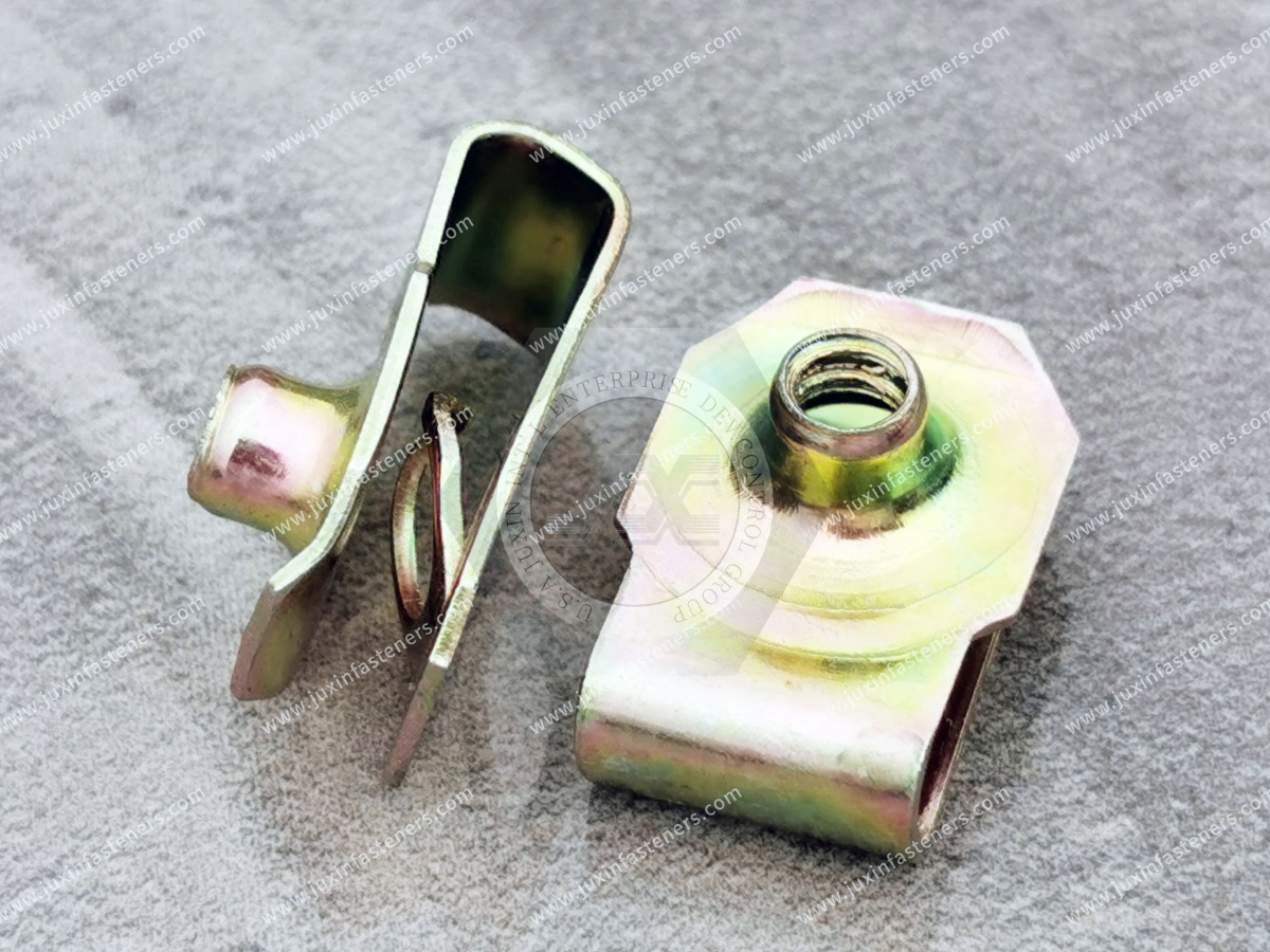
A spring clip must physically engage the panel.
Installation can therefore affect the surface.
Potential concerns include:
scratching;
indentation;
coating removal;
edge damage.
The severity depends on:
clip geometry;
spring force;
panel hardness;
coating;
installation method.
For mixed-metal EV enclosures, this interaction can also influence corrosion behavior.
Packaging space can be highly constrained around EV electronics.
Low-profile clip-on nuts may be useful where:
vertical clearance is limited;
covers sit close to internal modules;
external protrusion must be minimized.
However, “low profile” should not be treated as a universal dimensional category.
The actual envelope should be controlled by drawing.
See Low-Profile Strong-Grip Clip-On Nuts.
Some applications may benefit from a clip architecture incorporating a conventional nut element.
Potential considerations include:
thread engagement;
assembly geometry;
torque requirement;
envelope;
panel grip.
See Strong-Grip Clip-On Enclosed Hex Nuts.
This is a critical boundary in EV enclosure engineering.
A standard clip-on nut does not automatically provide:
watertight sealing;
gas sealing;
IP67;
IP68;
controlled gasket compression.
Enclosure sealing depends on the complete assembly.
Where an EV electronic enclosure has an ingress-protection requirement, the rating must be validated at the relevant enclosure or assembly level.
The fastener can influence the joint, but the clip itself should not be marketed as “IP67” simply because it is used inside an IP-rated enclosure.
If a cover compresses a gasket, engineers must consider:
fastener spacing;
cover stiffness;
gasket characteristics;
tightening process;
flange geometry.
A clip-on nut only provides one part of the mechanical fastening path.
It does not independently control gasket performance.
Power-electronics enclosures can have electromagnetic compatibility requirements.
A standard clip-on nut should not automatically be represented as providing:
EMI shielding;
RFI shielding;
controlled electrical continuity.
These functions depend on the complete enclosure architecture.
Likewise, a metal clip touching a metal panel does not automatically establish a compliant grounding or bonding connection.
Electrical performance can be affected by:
coatings;
contact pressure;
oxidation;
surface treatments;
joint design.
If grounding or bonding is required, the electrical interface must be specifically engineered and validated.
A clip-on nut used on an EV electrical enclosure should not automatically be represented as a high-voltage safety component.
Requirements involving:
electrical isolation;
creepage;
clearance;
touch protection;
high-voltage interlock systems
belong to the electrical and enclosure design.
Power-electronic modules may require service, inspection or replacement during the vehicle lifecycle.
Where the design permits it, replaceable edge fasteners can simplify service compared with some permanently installed thread systems.
If a clip thread becomes damaged and the panel remains suitable, the clip may be replaceable.
This can reduce the need for:
welding repair;
destructive insert removal;
panel replacement.
Repeated cover removal can affect:
screw threads;
clip threads;
panel edge;
coating;
gasket where present.
The allowable service cycle should therefore follow the validated assembly requirement.
EV production can involve:
manual assembly;
semi-automated assembly;
robotic or automated screwdriving;
automated fastener feeding.
Clip-on nuts used in high-volume production should be evaluated for:
orientation;
feeding behavior;
installation direction;
insertion force;
alignment;
packaging.
High-speed powered screwdriving can amplify alignment problems.
If the:
enclosure hole;
clip thread;
cover hole;
driver axis
are not adequately aligned, potential failures include:
cross-threading;
abnormal torque;
clip displacement;
thread damage.
Hole setback and clip position therefore remain critical EV production dimensions.
Many EV programs use metric threaded fasteners.
The RFQ should specify:
nominal diameter;
pitch;
mating screw specification.
Do not assume “M6 clip nut” provides enough information.
For detailed selection, see Metric Clip-On Nuts Selection Guide.
Two M6 EV clip-on nuts may have different:
grip ranges;
throat depths;
hole setbacks;
overall heights;
widths;
spring geometries;
materials;
finishes.
Therefore:
Same Thread Size ≠ Same EV Fastener
For edge-mounted clip nuts, the distance from the panel edge to the thread/hole center is a critical functional dimension.
Incorrect setback can cause:
misalignment;
difficult screw start;
clip movement;
cross-threading.
The panel drawing and clip drawing must therefore be evaluated together.
Lightweight aluminum sheet can behave differently from steel under local clip contact.
Engineers should consider:
local deformation;
edge condition;
panel thickness;
surface treatment;
installation force.
Increasing clip spring force is not automatically the correct solution for a soft or thin panel.
Excessive clip force can create:
difficult installation;
coating damage;
panel indentation;
clip overstress.
The objective is not maximum spring force.
It is:
Controlled Retention Appropriate to the Actual Panel
Potential issues include:
clip migration;
excessive insertion force;
panel damage;
coating damage;
hole misalignment;
cross-threading;
thread stripping;
corrosion;
service loosening.
For a systematic diagnostic workflow, see Clip-On Nut Failure Analysis.
If corrosion appears around a steel clip on an aluminum enclosure, investigate:
clip coating;
coating damage;
aluminum surface condition;
screw coating;
moisture path;
contamination;
exposed area ratio;
service environment.
Do not automatically conclude that the steel grade alone caused the problem.
If a joint changes behavior after thermal cycling, investigate:
differential expansion;
joint stack;
screw preload;
panel deformation;
gasket behavior;
material relaxation where relevant.
Again, the clip should be evaluated as part of the system.
| Engineering Requirement | Selection Consideration |
|---|---|
| Thread near enclosure edge | Clip-on nut may be suitable |
| Mid-panel blind thread | Consider rivet nut or another architecture |
| No welding desired | Clip-on nut is a no-weld option |
| Lightweight aluminum panel | Evaluate local panel behavior and corrosion interface |
| Steel panel | Match grip range and finish to application |
| Mixed steel/aluminum joint | Evaluate galvanic compatibility |
| Thermal cycling | Evaluate complete joint and material stack |
| Limited packaging height | Evaluate low-profile architecture |
| Serviceable cover | Replaceable clip may offer lifecycle advantage |
| Sealed enclosure | Seal must be designed separately |
| EMI requirement | Electrical enclosure design must address it |
| Grounding requirement | Dedicated electrical validation required |
| High vibration | Complete threaded joint must be validated |
| Automated assembly | Feeding, alignment and installation matter |
Is the fastener used on:
inverter;
OBC;
PDU;
auxiliary electronics;
thermal-management equipment;
service panel;
another enclosure?
Is it retaining:
cover;
bracket;
shield;
auxiliary module;
service panel?
Specify:
steel;
stainless steel;
aluminum alloy;
other material.
Include relevant surface systems.
Specify:
flange width;
edge radius;
hole setback;
throat-depth requirement.
Specify:
thread size;
pitch;
screw material;
screw finish;
screw length;
head style where relevant.
Include:
temperature range;
moisture;
salt exposure;
chemical exposure;
corrosion requirement.
Where steel and aluminum interact, review the complete material/coating interface.
Clarify whether separate requirements exist for:
sealing;
grounding;
EMI;
high-voltage safety.
Do not assign these functions to the clip unless specifically designed and validated.
Test:
Production Clip + Production Panel Finish + Production Screw + Production Assembly Process
before release.
A clip may assemble successfully on several prototype enclosures.
Volume production introduces:
material-lot variation;
panel tolerance;
coating variation;
automated assembly;
multiple fastener lots;
temperature variation;
line handling.
Production validation should therefore represent the actual manufacturing system.
Two suppliers may both offer an:
M5 Low-Profile EV Clip Nut
yet differ in:
grip range;
free-state geometry;
spring force;
throat depth;
hole setback;
material condition;
coating thickness;
thread geometry.
Therefore:
Same Commercial Description ≠ Equivalent Production Part
Supplier changes should be validated against the approved assembly requirements.
A clip-on nut may be attractive when:
the thread is near an accessible edge;
replacement is useful;
no setting tool is desired.
A blind rivet nut may be more appropriate when:
the threaded point is away from the edge;
only one side is accessible;
the enclosure geometry supports rivet-nut installation.
Neither is universally superior.
A self-clinching nut can create a fixed threaded attachment in suitable sheet material.
A clip-on nut remains edge-based and may offer easier replacement.
Selection depends on:
material;
thickness;
access;
production equipment;
service strategy.
A weld nut provides a welded threaded attachment.
A clip-on nut provides a mechanically retained edge attachment.
The choice depends on:
load;
location;
material;
manufacturing route;
serviceability.
For a full comparison, see Sheet-Metal Fastener Selection Guide.
EV engineers may search:
EV clip-on nuts;
electric vehicle spring nuts;
EV enclosure fasteners;
inverter enclosure fasteners;
OBC enclosure fasteners;
PDU enclosure fasteners;
aluminum enclosure clip nuts;
clip nuts for power electronics;
mixed-metal EV fasteners;
low-profile EV clip nuts;
EV service panel fasteners.
These queries indicate engineering selection intent.
Sourcing teams may search:
EV clip nut supplier;
electric vehicle spring nut manufacturer;
automotive electronics fastener supplier;
aluminum enclosure clip nut supplier;
power electronics fastener manufacturer;
custom EV clip nut;
metric EV clip nut supplier;
low-profile clip nut manufacturer.
These queries indicate commercial sourcing intent.
When requesting engineering and commercial evaluation from JUXIN FASTENERS, provide where applicable:
EV subsystem;
component application;
2D drawing;
3D model where available;
assembly drawing;
current fastener sample;
current supplier part number;
required thread size;
thread pitch;
mating screw specification;
screw material;
screw coating;
panel material;
aluminum alloy or steel specification where required;
nominal panel thickness;
thickness tolerance;
finished panel thickness;
panel surface treatment;
flange width;
edge geometry;
hole diameter;
hole setback;
throat-depth requirement;
fastener envelope;
required positional accommodation;
clip-retention requirement where defined;
mechanical joint requirements;
temperature range;
thermal-cycling requirement;
vibration requirement;
corrosion environment;
coating specification;
corrosion-test method;
test duration where specified by customer;
acceptance criteria;
galvanic-corrosion considerations;
sealing requirement at assembly level;
grounding/bonding requirement where applicable;
EMI/EMC-related enclosure requirements where applicable;
installation method;
screwdriving method;
automated-feeding requirement;
packaging requirement;
inspection requirements;
documentation requirements;
sample quantity;
prototype quantity;
production quantity;
estimated annual demand;
program timing;
customer-specific requirements.
They can provide threaded attachment points on suitable sheet-metal edges for EV electronic-enclosure covers, auxiliary brackets, service panels and other appropriate mechanical assemblies.
Potentially. Engineers should evaluate panel strength, clip fit, surface condition, galvanic compatibility and the complete material/coating system.
Dissimilar-metal contact can contribute to galvanic corrosion when the necessary environmental conditions are present. The complete interface should be evaluated rather than considering only the base metals.
No. Coatings can provide corrosion protection, but contact points and coating damage can occur. Galvanic isolation should not be assumed without validation.
Not automatically. Some designs provide limited positional accommodation, but thermal-expansion management is a system-level engineering issue.
Not automatically. Clip retention and threaded-joint loosening are different mechanical functions.
A standard clip-on nut should not be described as IP67 or IP68 by itself. Ingress protection is validated at the relevant enclosure or assembly level.
Not automatically. EMI/EMC performance depends on the complete enclosure and electrical design.
Metal-to-metal contact alone should not be assumed to provide a compliant grounding or bonding path. Electrical performance requires dedicated design and validation.
Many designs can be installed after finishing, but the effect on coating, effective panel thickness and corrosion behavior should be evaluated.
They can be useful where packaging height is constrained, provided the selected geometry satisfies the panel, thread and joint requirements.
Sometimes. The thread location, panel geometry, load, environment, manufacturing process and service strategy must first be evaluated.
JUXIN FASTENERS can review available drawings, samples, panel material and finish, mating screw, assembly requirements and annual demand to identify candidate clip-on nut configurations for evaluation.

A procurement request may begin:
“Need M6 spring clip for aluminum EV inverter enclosure.”
That still leaves critical questions unanswered.
Engineering should establish:
Which EV Subsystem?
What Does the Fastener Retain?
What Aluminum Alloy and Surface Treatment Are Used?
What Is the Finished Panel Thickness?
What Is the Edge Geometry?
What Is the Hole Setback?
What Mating Screw Is Used?
What Temperature Range Applies?
What Vibration Requirement Applies?
What Corrosion Requirement Applies?
How Is the Steel-Aluminum Interface Managed?
Is the Joint Part of the Sealing Boundary?
Does the Assembly Have Grounding or EMI Requirements?
How Will the Clip Be Installed in Production?
The sourcing path becomes:
EV Subsystem → Fastener Function → Panel Material → Finished Thickness → Edge Geometry → Thread / Screw
→ Mixed-Metal Interface → Environment → Clip Architecture → Samples → Assembly Validation → Controlled Specification → Production RFQ
That is the difference between sourcing a generic spring clip and specifying an EV enclosure fastening component for a controlled production program.
JUXIN FASTENERS supports OEM and industrial sourcing for:
EV clip-on nuts;
electric vehicle spring nuts;
U-nuts;
J-nuts;
low-profile clip-on nuts;
enclosed hex clip-on nuts;
tapping-screw clips;
metric clip-on nuts;
spring-steel edge clips;
stainless spring clips where appropriate;
drawing-based spring fasteners.
Potential applications include appropriate:
inverter covers;
on-board charger housings;
power distribution unit covers;
auxiliary electronic enclosures;
thermal-management equipment covers;
control-module brackets;
wiring-related brackets;
service-access panels;
lightweight steel and aluminum sheet assemblies.
For related engineering guidance, see:
Low-Profile Strong-Grip Clip-On Nuts
Strong-Grip Clip-On Enclosed Hex Nuts
Panel Thickness Selection Guide
Sheet-Metal Fastener Selection Guide
Carbon Steel Clip-On Nuts: Material & Coating Guide
Metric Clip-On Nuts Selection Guide
Sealing Blind Rivet Nuts for EV Battery Enclosures
For an EV clip-on nut RFQ or engineering review, send your drawing, application, panel material, finished panel thickness, panel surface treatment,
edge geometry, hole setback, mating screw specification, temperature and corrosion requirements, assembly process, sample quantity and estimated annual demand to:
For EV power-electronics and lightweight enclosure programs, the correct sourcing question is not simply:
“Which clip nut fits this M6 screw?”
It is:
“Which clip geometry, panel interface, material system, coating, thread and assembly process match the actual EV subsystem and its operating environment?”
 MORE NEWS
Contact Us
Tel.:
+86 020 8621 0320
+86 020 3121 6067
E-mail:
Technical Support:
Navigation
SEND INQUIREY