
Call Us
+86 136 6007 9809
Call Us
+86 136 6007 9809

Sep. 16, 2026
Modern automotive assembly, electrical equipment manufacturing, industrial machinery,
rail transportation equipment and enclosure production frequently require threaded fastening points on thin-gauge sheet metal, formed panels, brackets or restricted-access structures.
In these applications, a conventional nut may be difficult to install because the rear side of the panel is inaccessible.
Welding a nut can introduce additional manufacturing operations, thermal distortion or coating damage.
A rivet nut may be suitable for some applications, but it is not always the preferred solution when a removable spring clip nut can provide a simpler installation process.
Strong-Grip Clip-On Barrel Nuts are a category of clip-mounted threaded fasteners designed to position a threaded nut on a panel edge, flange,
mounting feature or prepared hole. Depending on the product geometry, they may also be described as clip nuts, spring clip nuts, sheet-metal nuts, speed nuts, U-nuts or captive clip nuts.
The correct product depends on the application geometry. The terms are related, but they should not be treated as interchangeable descriptions for every design.
JUXIN FASTENERS supports OEM and industrial sourcing requirements for customized fastening components.
Product selection should be based on the required thread, panel thickness, clip geometry, installation direction, material, surface treatment, mating screw and expected service conditions.
This guide explains the operating principles, product variations, engineering considerations, industry applications and procurement information required when evaluating clip-on barrel nuts for industrial assemblies.
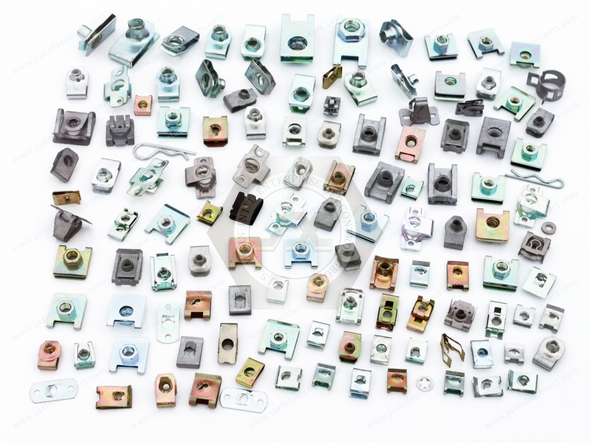
A typical clip-on barrel nut combines a threaded nut body with an elastic metal clip or spring element.
The threaded body provides the internal thread for the mating screw. The clip provides positioning, retention and spring action against the mating panel or mounting feature.
The actual construction varies according to the product design. Some versions are formed from spring steel with an integrated threaded section.
Other designs use a separate threaded barrel or nut body retained within a spring clip.
Before selecting a product, engineers should confirm the specific construction shown in the supplier drawing.
The threaded barrel or nut body provides the internal thread required for the mating screw.
Important specifications include:
Thread size and pitch
Metric or inch thread system
Thread tolerance
Thread engagement geometry
Nut body dimensions
Position of the thread relative to the clip
Access direction for the mating screw
Compatibility with the selected screw or bolt
A clip-on nut should not be selected only by nominal thread size.
Two products with the same M6 or 1/4-inch thread may have different barrel lengths, panel clearances, clip widths or installation requirements.
The spring clip provides the force required to retain the nut on the panel or mounting feature.
Depending on the design, the clip may:
Grip a panel edge
Engage a prepared hole
Retain the nut in a mounting position
Compensate for limited panel variation
Support pre-assembly before the screw is installed
Help maintain the relative position of the nut and panel
The clip’s spring behavior depends on its material, thickness, formed geometry, bend radius, free position and application-specific deflection.
The clip should not automatically be described as a guaranteed anti-loosening device. Its retention function and the joint’s resistance to loosening are separate engineering considerations.
The barrel position determines whether the mating screw can enter the thread without interference.
During design validation, engineers should review:
Screw approach angle
Clearance around the barrel
Distance from adjacent bends
Panel edge location
Tool access
Screw length
Thread engagement
Possibility of cross-threading
Nut movement during installation
A strong-grip clip-on barrel nut is useful only when its complete geometry is compatible with the assembly.
A spring clip can provide mechanical retention of the nut on a panel. This is different from the prevailing-torque function of a dedicated locking nut.
A clip-on nut may help prevent the nut from falling away during assembly or maintain its position before screw installation.
However, the assembled joint’s resistance to loosening depends on the entire fastening system.
Relevant factors include:
Joint preload
Thread friction
Bearing surface friction
External vibration
Transverse movement
Thermal expansion
Joint stiffness
Panel flexibility
Screw and nut compatibility
Installation procedure
Service loading
Therefore, a clip-on barrel nut should not be promoted as automatically “vibration-proof” or “tightening itself under vibration.”
The more accurate engineering description is a spring-retained fastening component that may be suitable for vibration-exposed
assemblies when the complete joint is correctly designed and validated.
Many clip-on nut designs are selected because they can be installed from one side of a panel.
The clip holds the nut in position, allowing the assembler to insert the mating screw without holding a separate nut behind the panel.
This can be valuable for:
Enclosed structures
Thin sheet-metal housings
Brackets
Interior vehicle panels
Electrical cabinets
Appliance housings
Equipment covers
Restricted-access assemblies
The exact installation method depends on the clip profile. Some designs clip over an edge, while others engage a hole or formed feature.
A clip-on nut may support one-sided assembly, but this does not make it equivalent to a blind-installed rivet nut.
A rivet nut is installed by deforming or expanding the body within a panel. A clip-on nut is generally retained by its clip geometry.
The selection should depend on:
Whether the panel edge is accessible
Whether a hole is available
Required pull-out resistance
Required torque resistance
Panel thickness
Installation space
Removability
Expected service loads
For applications requiring a permanently installed threaded insert in a closed panel, engineers should also consider Blind Rivet Nuts: Comprehensive Engineering Principles.
Industrial buyers may use different names for similar-looking products. Correct terminology helps engineers and procurement teams identify the intended design.
“Clip nut” is a broad commercial term for a nut retained by a spring clip or formed metal carrier.
The design may be intended for:
Sheet-metal edges
Flanges
Holes
Brackets
Automotive trim components
Equipment panels
The term alone does not define the exact clip geometry.
“Speed nut” is a common industry term for certain spring-type nuts used to speed up assembly.
The name can refer to multiple configurations, including U-shaped, J-shaped and other spring clip designs.
The engineer should confirm the actual drawing rather than relying only on the commercial name.
U-nuts and J-nuts generally describe clip shapes or mounting configurations.
A U-nut may clip over a panel edge or flange. A J-nut may use a different leg arrangement and thread position.
The product name should be accompanied by:
Drawing
Thread specification
Panel thickness range
Hole requirement
Clip orientation
Material
Surface treatment
“Barrel nut” may describe a threaded cylindrical nut body. In different industries, the term may also refer to furniture cross-dowel nuts, aerospace self-locking barrel nuts or other threaded components.
For this reason, the phrase clip-on barrel nut should be supported by a clear drawing and application description.
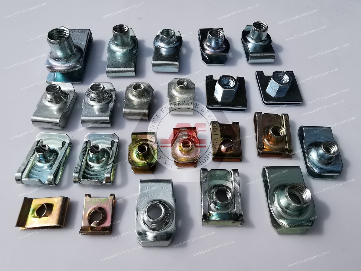
JUXIN FASTENERS can evaluate customer-specific fastening requirements according to the requested geometry, material, thread and application conditions.
The exact available configuration must be confirmed against the product drawing and quotation.
Spring steel is commonly considered for applications requiring elastic clip behavior and economical production.
Potential application areas include:
Industrial equipment housings
Appliance panels
Sheet-metal brackets
Automotive interior components
General mechanical assemblies
The selected material grade should be based on the required spring behavior, corrosion environment, forming requirements and customer specification.
A material description such as “spring steel” should not be treated as confirmation of a specific grade unless the grade is stated in the approved product documentation.
Some clip configurations may require a material with specific strength, forming or spring characteristics.
The suitability of alloy spring steel depends on:
Required elastic recovery
Clip deflection
Formed geometry
Fatigue exposure
Corrosion protection
Heat-treatment requirements
Customer specifications
The presence of a spring clip does not itself establish a confirmed fatigue life. Dynamic validation should be based on the actual product, joint and operating conditions.
Stainless steel may be considered for applications where corrosion resistance is important.
Potential application areas include:
Outdoor equipment
Electrical enclosures
Humid environments
Food-processing equipment surroundings
Industrial machinery
Marine-related equipment, subject to material suitability
Austenitic stainless steel grades should not be grouped together without considering corrosion exposure, strength, forming behavior, galling risk and mating screw compatibility.
Where applicable, stainless steel fastener requirements may be evaluated against the relevant scope of ISO 3506.
The standard should not be presented as automatically covering every clip geometry or every spring component.
Some customers may require a conductive fastening component for electrical or grounding-related assemblies.
Electrical continuity must be evaluated at the complete joint level. A conductive material alone does not guarantee a qualified grounding connection.
Relevant considerations include:
Contact surface condition
Coating or plating
Contact pressure
Oxide formation
Joint movement
Electrical resistance requirements
Applicable customer test method
Environmental exposure
A clip-on barrel nut should not be described as a qualified grounding or busbar fastener unless the design and application have been specifically validated for that function.
Clip-on barrel nuts do not necessarily fall under one universal product standard covering every commercial configuration.
The applicable requirements may combine thread standards, customer drawings, material specifications, coating requirements, inspection criteria and application-specific standards.
SAE J891:2016 is a relevant reference for metric and inch spring nuts within its defined scope.
SAE describes the standard as covering general and dimensional specifications for recognized spring nuts. It also notes that other configurations and provisions may be available.
The presence of SAE J891 in a sourcing discussion does not automatically mean that every clip-on barrel nut complies with it.
The actual product configuration and customer requirement must be compared with the standard’s scope.
For metric threaded components, relevant thread references may include:
ISO 261 for metric screw thread general plans
ISO 262 for selected metric screw thread sizes
ISO 965 for thread tolerances, where applicable
The applicable thread standard depends on the thread type, product design and customer specification.
A thread standard does not define the complete clip geometry, spring behavior or panel retention performance.
Material and surface-treatment specifications should be stated separately from the finished product description.
The RFQ may need to define:
Base material
Material grade
Heat-treatment requirements
Surface coating
Coating thickness, if specified
Corrosion-resistance test method
RoHS and REACH requirements
Appearance requirements
Restricted substances
Packaging and storage conditions
ASTM, ISO, EN or customer-specific requirements should only be cited when they apply to the requested material, coating or test.
One of the most common sourcing problems with clip-on nuts is selecting a product by thread size alone.
An M5, M6 or 1/4-inch thread does not define the complete installation interface.
The clip must be compatible with the actual panel thickness and its permitted manufacturing tolerance.
The RFQ should identify:
Nominal panel thickness
Minimum panel thickness
Maximum panel thickness
Coating or paint thickness
Panel material
Panel edge or hole geometry
Any local forming or reinforcement
A clip that is too loose may move during assembly. A clip that is too tight may be difficult to install or may damage the panel coating.
Clip-on products may be designed for different mounting conditions.
Edge-mounted designs generally depend on the panel flange or edge profile. Hole-mounted designs may depend on the hole diameter, hole position and local sheet geometry.
The supplier should receive a drawing or clear application image showing the intended mounting location.
The distance between the clip and the threaded centerline affects screw alignment.
Engineers should verify:
Centerline height
Nut body width
Clip length
Adjacent component clearance
Screw head clearance
Tool access
Panel bend location
These dimensions are especially important in compact automotive and electrical assemblies.
Some spring clip products are marketed using profile series or application-specific dimensional families.
However, “30 series,” “40 series” and “45 series” should not be used as universal descriptions for every clip-on barrel nut. Such designations may depend on a particular manufacturer, extrusion profile or product family.
The correct approach is to match the actual mounting geometry and approved drawing rather than assume that all products within a numerical series are interchangeable.
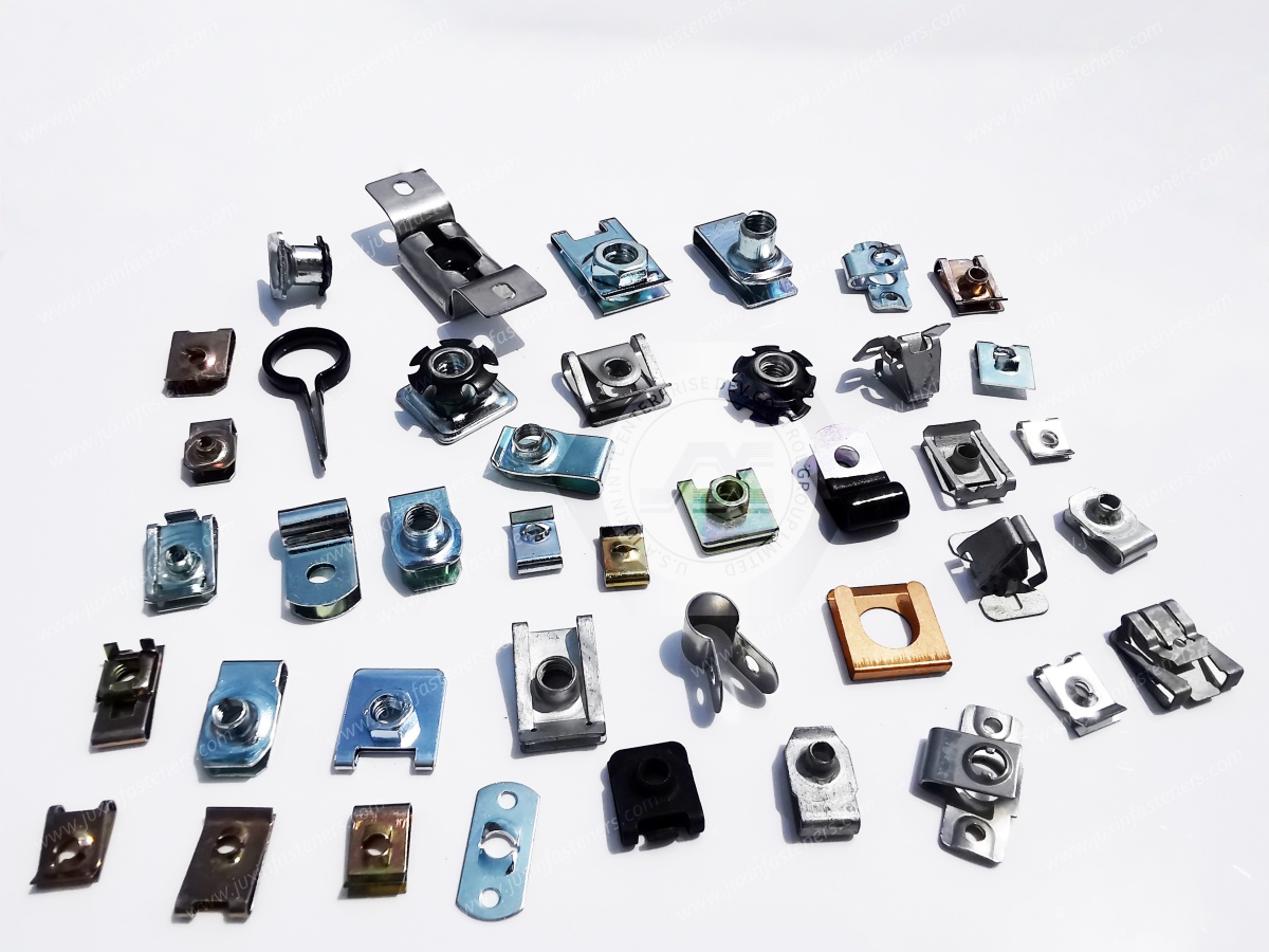
The spring clip is subjected to deflection during installation and, depending on the design, during panel engagement.
The engineering review should consider:
Free clip position
Installed clip position
Deflection range
Formed bend radius
Material spring behavior
Permanent deformation risk
Repeated installation requirements
The supplier should not claim a universal fatigue-life improvement from a slot, bend or spring feature without supporting product-specific validation.
Formed spring components can experience local stress concentration near bend transitions, corners, cut-outs and changes in cross-section.
Design review may consider:
Bend radius
Edge condition
Slot geometry
Material thickness
Forming direction
Local deformation
Repeated deflection
A stress-relief slot may be beneficial in a particular design, but it does not automatically improve fatigue performance in every application.
A clip-on nut used in a vibration-exposed assembly should be assessed as part of the complete joint.
The evaluation may include:
Joint preload
Screw type
Thread engagement
Panel stiffness
Contact surfaces
Transverse movement
Temperature variation
Assembly torque
Service vibration profile
Reuse requirements
The phrase “vibration-resistant” should be understood as an application objective requiring suitable design and validation, not as a blanket performance guarantee.
Different materials may expand at different rates during temperature changes.
For example, a metal clip attached to a coated sheet-metal panel may experience changes in contact condition during thermal cycling.
The engineering review should consider:
Material combinations
Operating temperature
Panel expansion
Clip deflection
Screw preload
Coating behavior
Joint movement
No specific temperature range should be assumed without the approved material and application specification.
Clip-on nuts may be considered for automotive sheet-metal and interior fastening applications where a threaded attachment point is required without installing a separate rear nut.
Potential uses include:
Interior trim brackets
Instrument-panel structures
Seat-related components
Door and closure components
Spoiler-related mounting components
Sheet-metal support brackets
Equipment covers
Automotive application approval requires attention to corrosion, vibration, assembly sequence, panel tolerances and customer-specific validation.
For related automotive fastening requirements, see Automotive High-Strength Fasteners: Bolts, Nuts, Clamps & Engineering Selection Guide.
Electrical enclosures often require threaded mounting points for covers, brackets, cable-management parts and internal components.
Clip-on nuts may be considered where:
The panel is thin
Rear access is restricted
A removable fastening point is required
The clip geometry is compatible with the enclosure
The joint does not require a different certified insert system
A clip-on nut does not automatically provide sealing, electrical bonding or enclosure ingress protection. Those functions must be evaluated separately.
Industrial machinery may use clip nuts for removable panels, guards, brackets and service-access components.
The design review should consider:
Maintenance frequency
Removal and reinstallation
Vibration
Panel stiffness
Corrosion exposure
Tool accessibility
Required fastening strength
Where the assembly requires a high-load structural connection, the engineer should evaluate whether a clip-on nut is appropriate or whether a different fastening architecture is required.
Appliance housings and internal sheet-metal components may use clip-mounted nuts for covers, brackets and support components.
The sourcing specification may include:
Panel thickness
Surface finish
Corrosion requirements
Assembly speed
Screw compatibility
Noise and vibration considerations
Appearance requirements
The appropriate clip geometry should be selected according to the actual panel design.
Rail equipment may contain sheet-metal panels, brackets and interior structures requiring captive or clip-retained threaded components.
Applications exposed to significant vibration, temperature variation or safety-related loading require application-specific engineering review and validation.
A general clip nut should not be represented as automatically approved for safety-critical or structural rail applications.
Aerospace fastening systems often use tightly controlled product specifications, material traceability and qualification requirements.
Clip-on barrel nuts for aerospace use must be evaluated against the exact customer or aerospace specification. ISO 12280, for example,
addresses sheet-metal spring retainers for self-locking barrel nuts within an aerospace-specific scope; it should not be used as a generic certification claim for all clip-on nuts.
JUXIN FASTENERS should review the customer’s drawing, required standard and qualification documentation before confirming suitability for an aerospace application.
The clip-on nut and mating screw should be selected as a compatible fastening system.
Important parameters include:
Thread size
Thread pitch
Screw length
Head style
Thread engagement
Material compatibility
Surface treatment
Installation torque
Reuse requirements
Environmental exposure
A screw that is too long may interfere with components behind the panel. A screw that is too short may provide insufficient thread engagement.
The customer should provide the screw specification whenever the clip-on nut is being developed as part of an existing assembly.
The appropriate surface treatment depends on the base material, service environment and customer requirements.
The engineering review may include:
Indoor or outdoor exposure
Humidity
Salt contamination
Chemical contact
Coating compatibility
Galvanic interaction
Storage conditions
Assembly damage to the coating
A corrosion test result should be connected to a defined test method and acceptance criterion.
ASTM B117, for example, is a salt spray test method and should not be treated as a universal predictor of field service life.
JUXIN FASTENERS can review the required surface-treatment specification for the intended application.
The final coating, material and compliance requirements should be confirmed in the quotation and technical documentation.
Clip-on barrel nuts are often purchased as production components rather than general-purpose hardware. Procurement teams should therefore evaluate both product fit and supply continuity.
The most effective RFQ package includes:
2D product drawing
3D model, if available from the customer
Thread specification
Material requirement
Surface-treatment requirement
Panel thickness
Installation description
Annual demand
Initial sample quantity
Production forecast
Inspection requirements
A drawing-based RFQ reduces ambiguity and helps prevent unsuitable substitutions.
The purchasing team should define the complete part number, including any relevant differences in:
Thread size
Clip geometry
Material
Coating
Orientation
Packaging
Revision level
Products with similar commercial names may have different installation interfaces. Part number control helps prevent mixing incompatible components.
Clip nuts may be supplied in bulk packaging, counted packaging or application-specific packaging, depending on the customer’s requirements.
The sourcing discussion may include:
Packaging quantity
Label format
Lot identification
Part number marking
Protection against deformation
Moisture protection
Delivery batch requirements
Inspection documentation
Packaging should protect the spring clip and threaded body from damage, contamination and unintended deformation during transportation.
A supplier evaluation may consider:
Ability to manufacture the specified geometry
Material sourcing
Forming process suitability
Thread quality
Surface treatment
Inspection plan
Drawing revision control
Production consistency
Communication during engineering changes
Specific certifications, testing systems and documentation should only be confirmed when they are applicable and available for the requested product.
The inspection plan should be based on the customer drawing and the functions that are critical to the application.
Possible inspection characteristics include:
Thread size and pitch
Thread gauge acceptance
Overall dimensions
Clip width and length
Nut position
Material verification
Surface treatment
Burrs and sharp edges
Clip deformation
Fit on the specified panel
Installation behavior
Spring retention or installation force may be relevant for certain designs, but the required test method and acceptance limits must be agreed upon for the actual product.
It would be inaccurate to claim automated optical sorting, specific process capability values, guaranteed zero defects or universal spring-tension testing without confirmed product-specific evidence.
Design engineers should begin with the installation interface rather than the product name.
Recommended review sequence:
Define the panel or mounting geometry.
Identify the required thread.
Confirm panel thickness and tolerance.
Determine whether the product clips over an edge or engages a hole.
Check screw access and clearance.
Review material and coating requirements.
Evaluate vibration and thermal conditions.
Confirm whether the nut is suitable for the expected joint loads.
Validate the assembly using samples or an agreed test plan.
Structural engineers should determine whether the clip-on nut is used for a non-structural attachment, a service panel or a load-bearing joint.
The evaluation should distinguish between:
Clip retention
Thread strength
Panel bearing strength
Pull-out behavior
Torque resistance
Joint preload
Local sheet deformation
Fatigue loading
The nut’s nominal thread size alone does not establish the load capacity of the complete joint.
Procurement teams should verify that the supplier’s quotation corresponds to the exact requested configuration.
Important questions include:
Does the quotation reference the correct drawing revision?
Is the material clearly identified?
Is the surface treatment specified?
Are the metric or inch threads correct?
Is the clip geometry suitable for the panel?
Are inspection requirements defined?
Is the packaging suitable for production?
Are samples required before approval?
Supply chain development should evaluate the component’s lifecycle requirements, including:
Engineering change management
Production continuity
Alternate material approval
Packaging stability
Lot traceability requirements
Delivery planning
Quality issue response
Communication of specification changes
A low unit price is not sufficient if the component is difficult to install, inconsistent with the panel geometry or vulnerable to supply interruptions.
A clip-on nut is not appropriate for every threaded fastening application.
Alternative fastening solutions may be considered when the application requires:
High structural load capacity
Permanent threaded installation
Defined pull-out resistance
Sealing performance
Electrical bonding
Safety-critical qualification
High-temperature service
Special aerospace specifications
Controlled prevailing torque
Repeated high-load installation
Possible alternatives include self-clinching nuts, weld nuts, blind rivet nuts, captive nuts or conventional bolted connections.
For sheet-metal applications requiring a permanently installed internal thread, review the relevant Blind Rivet Nut Engineering Guide.
For self-clinching applications, refer to the relevant JUXIN FASTENERS product and engineering documentation before selecting the installation method.
To receive an accurate technical review, customers should provide as many of the following details as possible.
Product name or existing supplier part number
2D drawing
3D model, if available
Part revision
Application photographs
Metric or inch thread
Nominal thread size
Thread pitch
Thread tolerance
Mating screw specification
Required thread engagement
Panel thickness
Panel material
Panel edge or hole geometry
Hole diameter, if applicable
Clip orientation
Available clearance
Installation direction
Required base material
Spring performance requirements
Surface treatment
Corrosion environment
RoHS and REACH requirements
Customer-specific restricted substances requirements
Static or dynamic loading
Vibration exposure
Temperature variation
Humidity or chemical exposure
Required service life
Reuse or removal requirements
Prototype quantity
Annual usage
Forecast quantity
Target delivery location
Packaging requirements
Inspection documentation
Sample approval requirements
Strong-Grip Clip-On Barrel Nuts can support efficient sheet-metal fastening when the clip geometry, threaded body, panel interface and application requirements are correctly matched.
JUXIN FASTENERS works with industrial and OEM customers evaluating customized fastening components for automotive, electrical equipment, machinery, enclosure and other manufacturing applications.
Our technical review should be based on the customer’s actual drawing, material requirements, mounting conditions and production objectives.
The appropriate product configuration, available manufacturing options and documentation should be confirmed during the quotation process.
For a technical evaluation, please send:
Product drawing or sample photograph
Thread specification
Panel thickness
Material and surface-treatment requirements
Application description
Estimated annual demand
Required inspection or compliance documentation
Contact JUXIN FASTENERS:
Email: info@juxinfasteners.com
Website: https://www.juxinfasteners.com/
Request a technical quotation for Strong-Grip Clip-On Barrel Nuts, spring clip nuts, sheet-metal fastening components or customized OEM fastening solutions.
Contact Us
Tel.:
+86 020 8621 0320
+86 020 3121 6067
E-mail:
Technical Support:
Navigation
SEND INQUIREY



