
Call Us
+86 136 6007 9809
Call Us
+86 136 6007 9809

Apr. 08, 2026
Automotive retaining rings are compact mechanical fasteners used to control axial movement of components on shafts or inside bores.
They may retain:
Bearings
Gears
Bushings
Sleeves
Pins
Spacers
Housings
Mechanical subcomponents
Depending on the design, they are commonly described as:
Retaining rings
Snap rings
Circlips
E-clips
External retaining rings
Internal retaining rings
Shaft retaining rings
Bore retaining rings
Although the component itself is small, the engineering problem is not simply:
“Which retaining ring diameter fits this shaft?”
Installed performance depends on the complete retention system:
Ring + Shaft / Bore + Groove + Axial Load + Material + Installation + Temperature + Corrosion + Dynamic Conditions + Validation
JUXIN FASTENERS supplies standard and drawing-based retaining rings, clips, pins and related fastening components for selected automotive,
EV, electrical, industrial machinery and OEM assemblies.
For engineers and procurement teams, the most important principle is:
The Groove Is Part of the Retaining System.
A correctly manufactured retaining ring installed into an incorrectly designed or damaged groove can still produce an unreliable assembly.
A retaining ring primarily restricts axial movement.
For an external ring:
Shaft → Groove → Retaining Ring → Retained Component
For an internal ring:
Housing / Bore → Groove → Retaining Ring → Retained Component
The ring provides an axial shoulder without requiring a threaded nut, bolt or machined integral shoulder in some designs.
Potential advantages include:
Compact axial packaging
Low component count
Rapid assembly
No tightening torque
No threaded retention hardware
Suitable integration into automated or semi-automated assembly
However:
Compact Fastener ≠ Simple Joint.
The ring and groove must be engineered together.
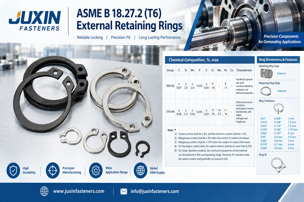
Terminology varies across industries and markets.
“Retaining ring” is a broad engineering term.
“Circlip” is widely used for retaining rings installed into grooves on shafts or inside bores.
“Snap ring” is also commonly used for elastic retaining rings.
“E-clip” refers to a particular external retaining-ring geometry installed radially onto a shaft groove.
“Stop ring” may be used commercially in some markets, but it can also refer to other components.
For technical drawings and RFQs, it is better to define the actual component:
External retaining ring
Internal retaining ring
E-clip
Circlip
Snap ring
Custom retaining ring
rather than relying only on the term “stop ring.”
A retaining ring should not be confused with a shaft collar.
A typical retaining ring engages a groove.
A shaft collar may use:
Set screws
Clamp-style geometry
Split-collar construction
to establish axial position on a shaft.
Therefore:
Retaining Ring ≠ Set-Screw Collar.
They are different fastening technologies and should not be combined into the same product specification.
External retaining rings are installed into grooves on shafts.
Their purpose is generally to prevent a retained component from moving axially beyond the ring location.
Potential applications include selected:
Gear assemblies
Electric motors
Actuators
Mechanical linkages
Transmission-related equipment
Pumps
Automotive auxiliary mechanisms
The actual suitability depends on the component, load and customer specification.
Internal retaining rings are installed into grooves inside:
Housings
Bores
Cylindrical cavities
They may retain components such as:
Bearings
Bushings
Sleeves
Internal mechanical elements
Selection should consider both the ring geometry and the housing material surrounding the groove.
The two types may look conceptually similar, but their installed geometry and loading conditions differ.
Therefore:
External Retaining Ring ≠ Internal Retaining Ring.
They should never be treated as interchangeable components simply because nominal diameters appear similar.
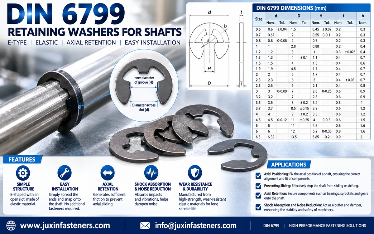
E-clips are external retaining components with a characteristic E-shaped profile.
They can be installed radially into a shaft groove rather than expanded over the end of the shaft in the same manner as some conventional external circlips.
This can be useful where:
Axial installation access is restricted
Rapid assembly is required
Compact packaging is important
Potential applications include:
Pins
Shafts
Linkages
Small mechanical mechanisms
Actuation systems
However:
E-Clip ≠ Universal Replacement for External Circlip.
Groove geometry, load capability, installation method and retention behavior differ.
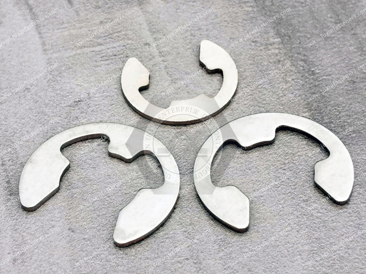
One practical advantage of some E-clip architectures is radial installation.
This can influence:
Assembly sequence
Tool access
Automation
Packaging
Serviceability
For production engineers, installation direction can therefore be just as important as component diameter.
The ring's primary mechanical function is usually axial retention.
Engineers should identify:
Maximum axial load
Static or cyclic loading
Shock loading
Load direction
Number of load cycles
Temperature
Required service life
But ring strength alone does not determine system capacity.
A retaining ring transfers load into the groove.
The load path is approximately:
Retained Component → Ring → Groove → Shaft / Housing
The system can therefore fail at:
The ring
The groove
The shaft
The housing
The retained component interface
This leads to a critical engineering principle:
Strong Ring ≠ Strong Retaining System.
The groove should not be treated as a secondary machining detail.
Depending on the ring design, important variables can include:
Groove diameter
Groove width
Groove depth
Groove side-wall geometry
Edge condition
Corner radius
Surface finish
Distance from shaft or bore end
The exact dimensions should follow the applicable ring specification and validated assembly design.
A retaining ring can meet every dimensional requirement on its own and still fail functionally if the groove is incorrect.
Potential groove problems include:
Excessive width
Insufficient depth
Excessive depth
Damaged groove edges
Incorrect radius
Burrs
Poor machining
Incorrect position
Therefore:
Ring Inspection Alone ≠ Retaining-System Validation.
If the groove is excessively wide, the ring may have unnecessary axial movement.
This can contribute to:
End play
Impact loading
Noise
Wear
Reduced positional control
If the groove is too narrow, installation or correct seating may become difficult.
Groove depth affects how the ring seats and how load transfers into the shaft or housing.
Incorrect depth can reduce:
Effective engagement
Support
Retention performance
There is no useful universal rule such as “deeper is always stronger.”
Deeper Groove ≠ Better Retention.
Removing additional shaft or housing material can also weaken the parent component.
The groove root geometry can influence stress concentration.
A sharp geometric transition can increase local stress.
But the groove radius must also remain compatible with the retaining ring.
Therefore groove design involves a balance between:
Ring seating
Manufacturing capability
Parent-component strength
Stress concentration
An external retaining ring may be stronger than the shaft groove supporting it.
If the shaft material is relatively soft, groove deformation may control failure.
Therefore:
Higher Ring Strength ≠ Higher Assembly Capacity.
The shaft material must be included in the engineering evaluation.
An internal retaining ring transfers axial load into the housing groove.
If the housing is:
Aluminum
Polymer
Cast material
Relatively soft alloy
the groove may become the limiting element.
This is especially important in lightweight automotive and EV assemblies.
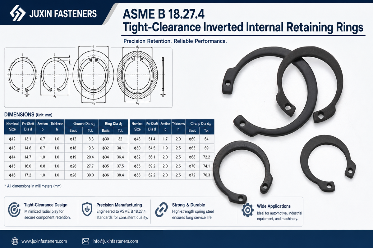
A hardened steel retaining ring may be installed in an aluminum housing.
The ring may have excellent mechanical strength.
But the softer aluminum groove can experience:
Local bearing deformation
Wear
Groove-edge damage
Therefore:
Harder Ring ≠ Stronger Aluminum Housing.
Parent-material behavior must be considered.
Under load, the retaining ring bears against the groove wall.
Possible failure mechanisms include:
Groove deformation
Groove-edge shear
Ring deformation
Ring disengagement
Parent-material yielding
The critical failure mode depends on the complete geometry and material combination.
A ring that retains a component successfully under static axial load may behave differently under:
Repeated impact
Vibration
Reversing load
Shock
Thermal cycling
Therefore:
Static Retention ≠ Dynamic Qualification.
Automotive assemblies should be evaluated according to actual operating conditions.
Some assemblies require controlled axial clearance.
Retaining-ring systems may therefore need to account for:
Component tolerance
Groove position
Ring thickness
Washer or spacer thickness
Thermal expansion
A retaining ring does not automatically eliminate all axial movement.
A ring provides retention.
It should not automatically be expected to perform the function of:
Thrust bearing
Precision spacer
Controlled preload system
If axial preload or precise end play is required, additional components or engineered interfaces may be necessary.
Retaining rings rely on controlled elastic behavior during installation and service.
Potential materials can include:
Spring steel
Carbon spring steel
Stainless spring materials
Customer-specified alloys
Material selection depends on:
Elastic requirement
Strength
Fatigue
Temperature
Corrosion
Manufacturing process
A retaining ring must often deform during installation and recover sufficiently to engage the groove.
Therefore its function depends on:
Material + Heat Treatment + Hardness + Geometry + Manufacturing Process
Two rings with identical nominal dimensions can behave differently if their materials or heat treatment differ.
This principle is particularly important during second-source qualification.
A supplier comparison based only on:
Outside diameter
Inside diameter
Thickness
may miss differences in:
Hardness
Elastic recovery
Permanent deformation
Installation behavior
Fatigue performance
Therefore:
Same Dimensions ≠ Functional Equivalence.
Stainless materials can be considered where corrosion resistance is important.
Potential applications may include environments exposed to:
Moisture
Humidity
Condensation
Selected chemicals
But:
Stainless Steel ≠ Corrosion-Proof.
The actual stainless grade, mechanical condition, mating material and environment must be considered.
Spring steel can provide suitable mechanical and elastic properties for many retaining-ring designs.
Surface protection may be required depending on the environment.
Potential finishing systems should be selected according to:
Corrosion requirement
Component geometry
Spring characteristics
Installation
Customer specification
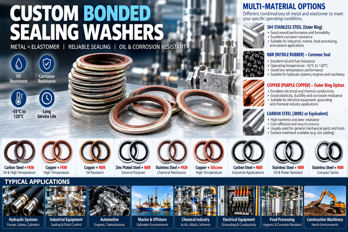
Depending on material and customer specification, retaining rings may use suitable:
Phosphate-based finishes
Zinc-based coatings
Zinc-nickel systems
Other engineered protective finishes
The coating system should be selected carefully because a retaining ring is an elastic component.
A coating can influence:
Corrosion
Thickness
Surface friction
Installation
Groove fit
Therefore:
Coating Substitution Can Be an Engineering Change.
A supplier should not change the finish simply because two coatings have similar color.
A retaining ring operates within a controlled geometric interface.
Surface-treatment thickness can alter the finished dimensions.
This can be particularly important where:
Groove clearance is limited
Ring thickness is tightly controlled
Installation behavior is sensitive
Therefore finished-component dimensions should be evaluated after the specified surface treatment where relevant.
A retaining ring may contact:
Carbon-steel shaft
Stainless shaft
Aluminum housing
Coated component
Mixed-metal interfaces can introduce galvanic considerations.
Therefore:
Corrosion-Resistant Ring ≠ Corrosion-Resistant Retaining System.
Laboratory salt-spray testing can support a defined coating requirement.
However:
Salt Spray Hours ≠ Field Service Life.
Actual automotive exposure can include:
Wet/dry cycles
Road salt
Temperature
Chemicals
Mechanical wear
The applicable OEM or customer corrosion specification should define the requirement.
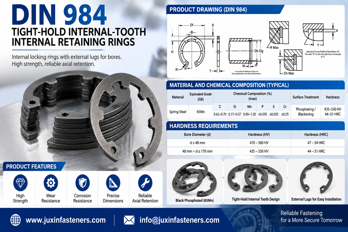
Retaining rings must be installed correctly into their grooves.
Installation variables can include:
Tooling
Installation direction
Ring expansion or compression
Groove accessibility
Component alignment
Verification of seating
Incorrect installation can damage an otherwise compliant ring.
An external circlip may need to expand during installation.
Excessive expansion can produce:
Permanent deformation
Reduced spring recovery
Distortion
Reduced groove engagement
Therefore:
More Expansion ≠ Better Installation.
The installation method should avoid unnecessary over-expansion.
Internal retaining rings may require compression during installation.
Excessive compression can similarly affect:
Geometry
Elastic recovery
Seating
Correct tooling and controlled handling matter.
After installation, the ring should be properly seated according to the designed assembly condition.
A partially seated retaining ring can create a serious retention problem even if the component itself is dimensionally correct.
For suitable production processes, inspection may include:
Visual confirmation
Automated vision
Mechanical presence detection
Application-specific functional checks
This distinction matters in automated assembly.
A ring may physically be present but not fully engaged.
Therefore:
Component Presence ≠ Correct Installation.
Production controls should detect the failure mode that matters.
Depending on ring design, installation may use:
Circlip pliers
Dedicated installation tools
Radial E-clip applicators
Automated feeding and installation equipment
Tooling should match the ring architecture.
An E-clip should not automatically be described as requiring the same tooling as a conventional circlip.
Retaining rings may be used in selected electric motor assemblies for axial positioning or retention of components such as:
Bearings
Shafts
Rotating subcomponents
Potential requirements can include:
Compact packaging
Controlled axial position
High cycle life
Temperature resistance
But high-speed rotating systems require application-specific engineering.
A retaining ring installed on a rotating shaft may experience rotational effects in addition to axial loading.
At elevated rotational speeds, ring geometry and installation condition can become increasingly important.
Therefore:
Static Shaft Application ≠ High-Speed Rotating Application.
High-speed systems should follow the relevant design and customer validation requirements.
Potential applications can include axial retention of selected:
Gears
Bearings
Sleeves
Mechanical subcomponents
Important considerations may include:
Axial load
Shock
Lubrication environment
Temperature
Groove geometry
Fatigue
Primary transmission and safety-related components require OEM-specific engineering and validation.
Retaining rings may appear in selected mechanical subassemblies.
However, steering and suspension systems can contain safety-critical components.
General-purpose retaining rings should not automatically be described as suitable for:
Ball joints
Steering mechanisms
Suspension retention
without the applicable OEM design specification and formal validation.
Less safety-critical mechanical systems may use retaining rings or E-clips in:
Adjustment mechanisms
Hinges
Linkages
Actuators
Brackets
Selection still depends on load, groove and assembly requirements.
Retaining rings may be used in selected:
Motors
Fans
Pumps
Actuators
Valve mechanisms
within HVAC and thermal-management equipment.
Temperature and corrosion conditions should be included in the specification.
Electric vehicles introduce additional:
Electric motors
Pumps
Cooling equipment
Power electronics
Actuators
where retaining components may be required.
However:
Retaining Ring ≠ EV-System Qualification.
High-voltage, thermal, structural and safety requirements belong to the complete system.
The same retaining-ring engineering principles apply beyond automotive applications.
Potential uses include:
Motors
Gearboxes
Actuators
Linear mechanisms
Automation equipment
Robotics
This makes retaining rings relevant to OEM buyers across multiple industrial sectors.
Retaining rings may be used in:
Motor assemblies
Switch mechanisms
Actuators
Fans
Mechanical subassemblies
Their mechanical function should remain separate from electrical compliance.
Metal Retaining Ring ≠ Qualified Electrical Connection.
Depending on design, manufacturing can involve:
Stamping
Forming
Heat treatment
Deburring
Surface finishing
Dimensional control
Functional performance depends on the process sequence as well as raw material.
A correct spring-steel grade does not by itself guarantee:
Correct hardness
Correct elasticity
Correct geometry
Correct groove engagement
Therefore:
Material Certificate ≠ Finished Component Qualification.
Finished-component controls remain necessary.
Retaining rings interact with:
Grooves
Shafts
Housings
Installation tooling
Excessive burrs or sharp uncontrolled edges can affect:
Installation
Seating
Surface damage
Functional fit
Edge condition should therefore be controlled according to the drawing and function.
Manufacturing, heat treatment or surface finishing can affect ring geometry.
Distortion may influence:
Installation
Groove seating
Load distribution
Dimensional inspection should therefore focus on functionally relevant characteristics.
Depending on the application, inspection can include:
Material verification
Dimensions
Thickness
Groove-interface dimensions
Hardness
Surface condition
Coating
Visual inspection
Functional installation checks
Where required, customer-specific testing may also evaluate mechanical performance.
Checking only the ring may miss an assembly-level problem.
For critical fit and retention, useful validation may involve a representative:
Ring + Groove + Shaft / Housing
This is especially important during:
New product development
Supplier changes
Material changes
Coating changes
Second-source qualification
Potential contributors can include:
Incorrect groove
Incomplete seating
Excessive axial load
Ring deformation
Installation damage
Dynamic loading
The corrective action should identify the actual mechanism.
Potential causes include:
Soft parent material
High axial load
Insufficient groove support
Impact
Incorrect groove geometry
Changing to a stronger ring may not solve this problem.
Possible causes include:
Excessive expansion
Excessive compression
Wrong tooling
Incorrect installation sequence
In this case, the failure begins during assembly rather than vehicle service.
Possible contributors include:
Groove width
Ring thickness
Component tolerance stack
Spacer thickness
Groove location
A tighter ring is not automatically the correct solution.
Tolerance analysis should identify the source.
Possible contributors include:
Unsuitable material
Unsuitable coating
Coating damage
Galvanic interaction
Service environment
Again:
Corrosion Complaint ≠ Automatically Change to Stainless Steel.
The assembly environment should be reviewed first.
If a retaining ring disengages, the immediate reaction may be:
“We need a stronger retaining ring.”
But the actual problem may be:
Wrong groove
Soft shaft
Installation damage
Excessive axial play
Dynamic impact
Incomplete seating
Therefore:
Failure Analysis Should Follow the Load Path.
A threaded nut may provide adjustable axial clamping and serviceability.
A retaining ring can provide compact axial retention without tightening torque.
The technologies solve different problems.
Use a retaining ring when the assembly architecture is designed around groove-based axial retention.
Use a threaded solution when the joint requires controlled threaded clamping or adjustment.
A shaft collar may be appropriate when:
A groove is undesirable
Position needs adjustment
Different assembly architecture is required
A retaining ring may be preferable when:
Compact packaging is important
A dedicated groove is acceptable
Fixed axial positioning is required
The technologies should not be treated as synonyms.
A retaining ring primarily controls axial movement through groove engagement.
A pin may provide:
Alignment
Shear transfer
Pivoting
Retention
These are different load paths.
A request such as:
“20 mm retaining ring”
may be insufficient.
Procurement should identify:
External or internal
Ring type
Applicable standard or drawing
Shaft or bore diameter
Groove dimensions
Material
Hardness where specified
Surface treatment
Axial load
Environment
Installation method
Annual volume
This reduces quotation errors and supplier mismatches.
Depending on product design, retaining rings may be defined by applicable international or customer specifications, including relevant:
DIN retaining-ring standards
ISO requirements
SAE specifications where applicable
Customer drawings
OEM engineering specifications
The exact standard should be matched to the specific ring architecture rather than added generically to every product.
Standardized retaining rings are often preferred where:
Standard shaft or bore geometry is available
Load requirement fits the standard design
Packaging permits the standard ring
Custom designs may be required where:
Packaging is restricted
Groove geometry is proprietary
Axial load differs from standard solutions
Installation method is specialized
Integrated functions are required
JUXIN FASTENERS can review suitable drawing-based retaining-ring and clip projects.
Engineering review can consider:
Ring geometry
Material
Thickness
Groove interface
Heat treatment
Hardness
Surface treatment
Installation
Annual volume
A complete drawing is strongly preferred for custom components.
Retaining rings are a good example of why second sourcing cannot rely only on dimensional similarity.
Qualification should compare:
Drawing and revision
Material
Thickness
Heat treatment
Hardness
Ring geometry
Surface treatment
Finished dimensions
Installation behavior
Groove engagement
Functional performance
Therefore:
Same Dimensions ≠ Functional Equivalence.
Changing:
Spring steel grade
Stainless grade
Heat treatment
Hardness
can affect elastic behavior.
Therefore a supplier should not substitute material based only on nominal strength or corrosion resistance.
Changing from one surface treatment to another can affect:
Thickness
Corrosion
Friction
Installation
Fit
The new finish should be reviewed before production approval.
Procurement should compare more than unit price.
A useful model is:
Total Installed Cost = Part Price + Groove Manufacturing + Installation + Tooling + Inspection + Rework + Scrap + Downtime + Logistics + Supply Risk
A low-cost ring that is difficult to feed or install can increase assembly cost.
A ring with stable automated installation may reduce total production cost.
For high-volume production, engineers should consider:
Ring feeding
Orientation
Installation direction
Tool access
Seating verification
Error detection
Component geometry should support the intended production process.
For a useful technical and commercial quotation, provide:
2D drawing
3D model where available
Part number
Drawing revision
Application
External / internal / E-clip type
Shaft or bore diameter
Groove dimensions
Parent material
Axial load requirement
Ring material
Heat treatment
Hardness requirement
Surface treatment
Service temperature
Corrosion environment
Rotational speed where relevant
Installation method
Annual volume
Sample quantity
Validation requirement
Applicable ISO, DIN, SAE or customer specification
Where possible, provide:
Shaft drawing
Shaft material
Shaft hardness
Groove diameter
Groove width
Groove location
Surface treatment
Rotational speed
Axial load direction
Provide:
Housing drawing
Housing material
Bore diameter
Groove geometry
Wall thickness
Axial load
Temperature
Surface treatment
This is particularly important for aluminum or other relatively soft housings.
A controlled development process can follow:
Application → Axial Retention Requirement → Shaft / Bore → Load → Ring Architecture → Groove → Material → Heat Treatment
→ Surface Treatment → Drawing Review → Sample → Installation Trial → Functional Validation → Approval → Production
For second sourcing:
Approved Drawing → Existing Assembly → Material & Process Comparison → Sample → Groove Fit → Installation → Functional Validation → Production Approval
The original version of this article grouped retaining rings and wood screws together.
From an engineering and search-intent perspective, these are unrelated fastening technologies.
Traditional wood screws are designed primarily for wood-based substrates.
Modern automotive production is dominated by:
Sheet metals
Aluminum
Engineering plastics
Composites
Molded components
Purpose-designed inserts and threaded interfaces
For these substrates, engineers should select fastening technology according to the actual parent material.
A common specification mistake is assuming that a screw that cuts into wood will also be appropriate for molded plastic.
It may not be.
Thermoplastics require consideration of:
Polymer
Boss geometry
Hole diameter
Wall thickness
Thread profile
Installation torque
Stress
Creep
Therefore:
Wood Screw ≠ Engineered Thread-Forming Screw for Plastic.
Depending on the design, engineers may evaluate:
Thread-forming screws for plastic
Application-specific self-tapping screws
Threaded inserts
Machine screws with installed inserts
Clips and captive fasteners
The correct technology depends on the polymer and joint.
For thin metal assemblies, potential solutions include:
Thread-forming screws
Self-tapping screws
Rivet nuts
Weld nuts
Self-clinching fasteners
Blind rivets
Again:
Parent Material + Access + Load + Serviceability + Production Process
should determine the choice.
A SEMS screw combines a screw with a captive washer or washer system.
This can improve:
Part handling
Assembly efficiency
Washer retention
But:
SEMS Screw ≠ Automatically Vibration-Proof.
And:
SEMS Washer ≠ Automatically Sealing Washer.
The washer design and complete joint determine function.
Self-drilling screws can eliminate a separate drilling operation in suitable applications.
However, they are not automatically the correct choice for every automotive thin-sheet joint.
Engineers should consider:
Sheet material
Thickness
Hole requirement
Thread engagement
Installation process
Serviceability
This page should function as the dedicated Automotive Retaining Rings / Circlips / E-Clips engineering resource.
Recommended internal links include:
Automotive Washers, Rivets & Pins → positioning, retention and permanent joining technologies
Automotive Fastener Selection Guide → overall automotive fastening technology selection
Automotive Self-Tapping Screws → direct-threading solutions for metal and plastic
Automotive Thin Sheet Fasteners → weld nuts, rivet nuts and self-clinching nuts
Automotive Threaded Fasteners → preload, friction and locking
Automotive Fastener Quality Control → supplier qualification and inspection
Stainless Steel Fasteners → corrosion-resistant material selection
Fastener Surface Treatment & Coating Selection → coating engineering
Zinc-Nickel Coated Fasteners → corrosion protection for automotive fasteners
Custom Fastener Manufacturing → drawing-based manufacturing and DFM
Use the existing indexed JUXIN FASTENERS URL when implementing these internal links.
A retaining ring is a mechanical fastener used to restrict axial movement of a component on a shaft or inside a bore by engaging a designed groove.
Circlip is a commonly used term for certain elastic retaining rings. “Retaining ring” is the broader category.
An external retaining ring installs into a groove on a shaft. An internal retaining ring installs into a groove inside a bore or housing.
An E-clip is an external retaining component with an E-shaped profile that typically installs radially into a shaft groove.
Not necessarily. E-clips use a different installation architecture from many conventional circlips and may use dedicated manual or automated installation tools.
No. A retaining ring normally engages a groove, while a shaft collar uses a different clamping or set-screw retention mechanism.
The ring itself is only one factor. Groove geometry, shaft or housing material, axial load, installation and dynamic conditions also affect the retaining system.
No. Ring type, groove dimensions, material, axial load, environment and installation method should also be specified.
The groove transfers load from the ring into the shaft or housing. Incorrect groove geometry can cause failure even when the ring itself is correct.
Not automatically. Groove depth affects ring engagement but also removes parent material. The correct geometry should follow the applicable design specification.
Not necessarily. If the groove or parent material is the weak element, increasing ring strength may not increase assembly capacity.
Yes, in suitable designs, but the softer housing material and groove behavior should be considered when evaluating axial load.
Stainless steel can improve corrosion resistance in suitable environments, but it does not make the complete assembly corrosion-proof.
A coating change can affect corrosion, dimensions, friction and installation behavior. It should be treated as an engineering change where these characteristics are functional.
Compare drawing revision, material, heat treatment, hardness, geometry, coating, installation behavior and functional performance rather than dimensions alone.
Traditional wood screws have limited relevance to modern automotive production. Purpose-designed thread-forming screws, self-tapping screws,
inserts, rivet nuts, clips and other fastening technologies are generally more appropriate for automotive metals, plastics and composites.
It should not be assumed suitable. Plastic fastening requires a screw and boss design matched to the polymer, hole geometry, thread profile and installation conditions.
Send the ring drawing, shaft or bore drawing, groove geometry, application, axial load, parent material, ring material, heat treatment,
surface treatment, temperature, environment, installation method, annual volume and validation requirements.
The most important principle for retaining-ring engineering is:
The Ring and Groove Form One Mechanical System.
Selection should not stop at:
“What ring diameter do we need?”
Instead evaluate:
Axial Load → Shaft / Bore → Groove → Ring → Material → Heat Treatment → Surface Treatment → Installation → Environment → Validation
This prevents several common specification errors:
Retaining Ring ≠ Shaft Collar
External Ring ≠ Internal Ring
E-Clip ≠ Universal Circlip Replacement
Ring Strength ≠ Retaining-System Strength
Correct Ring + Wrong Groove = Wrong Joint
Deeper Groove ≠ Better Retention
More Installation Expansion ≠ Better Installation
Installed Ring ≠ Correctly Seated Ring
Same Dimensions ≠ Functional Equivalence
For modern automotive assemblies, the same functional-selection principle also applies to screw technology:
Wood Screw ≠ Plastic Thread-Forming Screw
SEMS Screw ≠ Automatic Anti-Loosening Solution
Self-Drilling Screw ≠ Universal Thin-Sheet Solution
JUXIN FASTENERS supports selected automotive and industrial OEM projects with:
External retaining rings
Internal retaining rings
Circlips
Snap rings
E-clips
Spring clips
Retaining pins
Spring pins
Custom stamped retaining components
Drawing-based fastening components
For an effective RFQ, provide:
2D Drawing + 3D Model + Part / Revision + Application + Ring Type + Shaft / Bore + Groove Geometry + Parent Material + Axial Load
+ Ring Material + Heat Treatment + Surface Treatment + Environment + Installation Method + Annual Volume
For rotating applications, also provide:
Rotational Speed + Temperature + Dynamic Load + Required Validation
For aluminum housings or other relatively soft parent materials, provide the mating-component drawing so the groove can be evaluated as part of the retention system.
JUXIN FASTENERS
Automotive Retaining Rings | Circlips | Snap Rings | E-Clips | Spring Clips | Custom OEM Fasteners
Email: info@juxinfasteners.com
Website: www.juxinfasteners.com
Contact Us
Tel.:
+86 020 8621 0320
+86 020 3121 6067
E-mail:
Technical Support:
Navigation
SEND INQUIREY



