
Call Us
+86 136 6007 9809
Call Us
+86 136 6007 9809

May. 19, 2026
Threaded inserts are widely used to create durable, reusable metal threads in plastic components where direct threading into the polymer cannot provide the
required assembly performance, service life or repeated disassembly capability.
In automotive manufacturing, these inserts can be found in suitable:
Interior modules
Instrument panels
Infotainment housings
Electronic control-unit housings
Sensor assemblies
Lighting components
HVAC components
Plastic brackets
Electrical enclosures
EV electronic modules
Thermal-management components
Composite and polymer assemblies
But specifying a threaded insert should not begin with the question:
“Which brass insert fits this screw?”
The more important engineering question is:
“How will this insert transfer load into this specific polymer component?”
A reliable insert joint depends on the complete system:
Polymer + Polymer Condition + Boss Geometry + Pilot Hole + Insert Geometry + Installation Process + Mating Screw + Thread Engagement
+ Assembly Torque + Service Load + Temperature + Environment
This leads to one of the most important principles in threaded-insert engineering:
Strong Insert ≠ Strong Plastic Joint.
JUXIN FASTENERS supplies standard and drawing-based threaded inserts, brass inserts, knurled inserts and precision fastening components for selected automotive,
electronics, electrical equipment, telecommunications, industrial and OEM plastic assemblies.
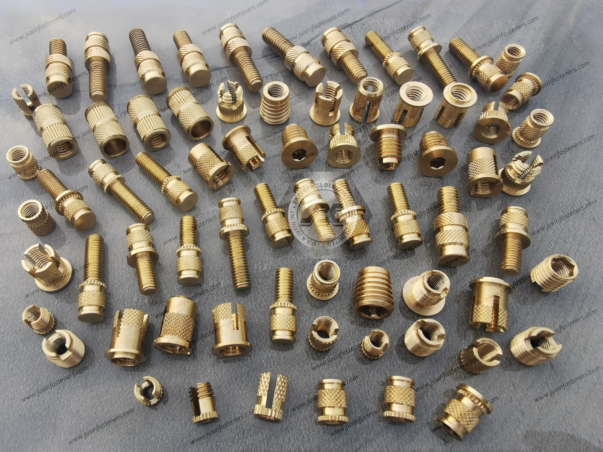
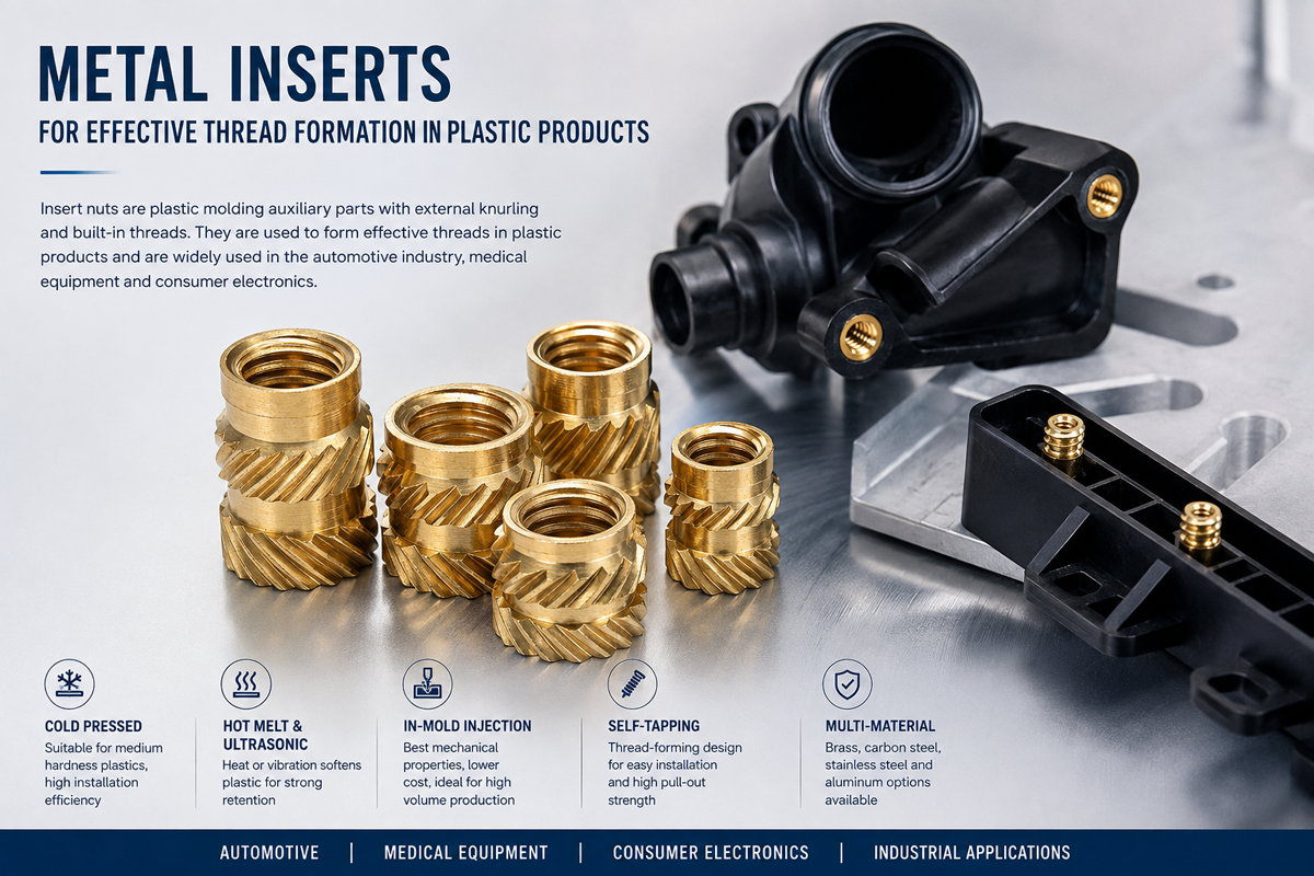
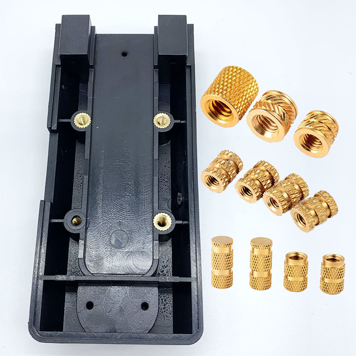
A threaded insert for plastic is a metal component installed into a polymer part to provide a durable internal thread.
Depending on the component design and manufacturing process, installation can include:
Heat staking / thermal insertion
Ultrasonic insertion
Insert molding
Press-in installation for suitable designs
Other application-specific insertion processes
The insert normally transfers screw-generated loads into the surrounding polymer through combinations of:
Mechanical interlocking
Knurl geometry
Undercuts
Polymer flow
Bearing surfaces
Axial engagement
The insert therefore cannot be evaluated independently from the plastic surrounding it.
Thread-forming screws can be effective in many polymer assemblies.
Threaded inserts become attractive where the design requires characteristics such as:
Repeated assembly and disassembly
Reusable machine-screw threads
Higher resistance to thread wear
Greater load-transfer capability in a properly designed boss
Stable service interfaces
Modular component replacement
The engineering decision is not:
Insert = Better Than Screw
It is:
Application Requirements → Direct Thread vs Insert → Installation Method → Joint Validation
| Engineering Factor | Threaded Insert | Thread-Forming Screw |
|---|---|---|
| Repeated service | Often advantageous | Depends strongly on polymer and service cycles |
| Separate installation step | Usually required | Often not required |
| Machine-screw interface | Yes | No separate metal female thread |
| Boss design | Insert-specific | Screw-specific |
| Initial component cost | Generally higher | Often lower |
| Installation process | Thermal, ultrasonic, molded-in or design-specific | Screwdriving |
| Failure mode | Insert pull-out, rotation, boss cracking, thread damage | Plastic thread stripping, boss cracking, screw failure |
| Best choice | Application-specific | Application-specific |
A lower fastener piece price does not necessarily mean a lower installed-system cost.
Engineers sometimes compare inserts by:
Thread size
Outside diameter
Length
Knurl style
without first considering the polymer.
This reverses the engineering process.
The parent polymer frequently controls the installed joint.
Relevant variables can include:
Polymer family
Exact grade
Reinforcement
Filler content
Moisture condition
Molded fiber orientation
Wall thickness
Temperature
Aging
Chemical exposure
Processing history
Therefore:
Same Insert + Different Polymer ≠ Same Joint Performance.
Terms such as:
PA66
PBT
PC
ABS
PP
POM
identify broad polymer families, not complete installed-joint performance.
For example, polymer behavior can change with:
Glass-fiber reinforcement
Mineral filler
Flame-retardant formulation
Moisture
Temperature
Mold processing
Recycled-content requirements
Additive packages
An insert validated in one polymer grade should not automatically be transferred to another grade without review.
Heat-set and ultrasonic insert technologies are commonly associated with thermoplastics because controlled local softening can
allow polymer to flow around the insert's retention features.
The general principle is:
Controlled Polymer Flow → Retention Geometry Filled → Polymer Solidifies → Mechanical Interlock
But the process window depends on the polymer and component geometry.
Too little energy can result in incomplete installation.
Too much energy can damage:
Boss geometry
Surrounding plastic
Insert position
Surface appearance
Therefore:
More Installation Energy ≠ Better Insert Installation.
Not every plastic behaves like a remeltable thermoplastic.
Thermosets and some composite structures may require different:
Insert geometries
Installation methods
Hole preparation
Load-transfer strategies
Therefore:
Threaded Insert for Plastic ≠ Universal Insert for Every Polymer or Composite.
The substrate and manufacturing process must be identified before selecting the insert.
A high-quality insert installed into a poorly designed boss can still fail.
Boss design can influence:
Pull-out resistance
Torque-out resistance
Radial stress
Cracking
Installation stability
Long-term joint performance
Important parameters can include:
Boss outside diameter
Boss wall thickness
Boss height
Pilot-hole diameter
Hole depth
Edge distance
Nearby ribs
Mold-flow direction
Insert depth
The correct geometry should be established through the insert design, polymer behavior and assembly validation.
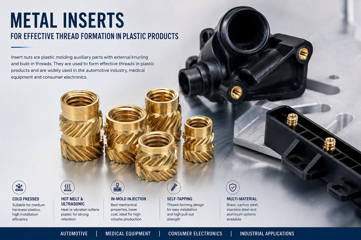
Increasing boss diameter or wall thickness can improve structural capacity in some designs.
But excessive material can also create molding issues such as:
Sink
Warpage
Cooling variation
Internal stress
The insert boss should therefore be designed as part of the molded component rather than oversized without analysis.
The hole receiving the insert is not merely a clearance hole.
Its diameter can influence:
Polymer flow
Insertion force
Final retention
Boss stress
Insert alignment
Therefore:
Pilot Hole ≠ Clearance Hole.
A hole that is too small may create excessive radial stress.
A hole that is too large may reduce mechanical interlock.
For blind-hole applications, engineers should consider:
Insert length
Hole depth
Bottom clearance
Plastic displacement
Screw engagement
An insert should not be forced against the bottom of an inadequately designed hole.
The external geometry of a threaded insert transfers load into the surrounding polymer.
Potential features include:
Straight knurls
Helical knurls
Opposing diagonal knurls
Diamond-type patterns
Grooves
Undercuts
Flanges
Tapered lead geometry
Different features influence different aspects of retention.
The correct question is not:
“Which knurl looks strongest?”
It is:
“Which geometry creates the required load transfer in this polymer using this installation process?”
Deep or aggressive knurl geometry can increase mechanical interlocking.
But it can also increase:
Installation stress
Required polymer displacement
Risk of boss cracking
Sensitivity to hole dimensions
Therefore:
More Aggressive Knurl ≠ Automatically Higher Joint Strength.
The insert geometry must be balanced against the substrate.
Pull-out describes resistance to axial extraction of the insert from the plastic.
Performance can depend on:
Insert length
Outside geometry
Undercuts
Polymer
Boss geometry
Installation quality
Temperature
But:
Pull-Out Strength ≠ Complete Joint Strength.
The assembly may fail in another mode first.
Torque-out describes resistance to rotation of the insert within the plastic.
It is strongly influenced by:
Knurl geometry
Insert diameter
Polymer
Boss
Installation process
And:
Pull-Out ≠ Torque-Out.
An insert can perform well in axial extraction but poorly in rotation, or vice versa.
Both should be evaluated according to the actual load path.
This distinction is especially important.
Insert torque-out concerns rotation of the entire insert within the parent plastic.
Screw self-loosening concerns relative rotation in the threaded joint.
They are different failure mechanisms.
Therefore:
Torque-Out ≠ Anti-Loosening Performance.
A threaded insert creates two important mechanical interfaces:
Interface 1: Screw ↔ Internal Metal Thread
Interface 2: Insert ↔ Polymer
The assembly can fail at either interface.
Possible failures include:
Screw failure
Internal thread stripping
Insert rotation
Insert pull-out
Polymer cracking
Boss failure
Therefore:
Strong Internal Thread ≠ Strong Installed Insert Joint.
Installing a higher-strength mating screw does not increase the strength of the surrounding polymer.
In some cases, a stronger screw can simply shift failure to:
Insert thread
Insert retention
Plastic boss
The mating screw should therefore be selected as part of the complete joint.
Internal thread requirements should be defined according to the applicable drawing and thread standard.
For ISO metric threads, tolerance classes such as 6H may be appropriate where specified.
However:
6H Thread ≠ Complete Insert Performance Specification.
Thread quality does not define:
Pull-out
Torque-out
Installation behavior
Boss strength
Thermal performance
The insert requires both dimensional and functional specifications.
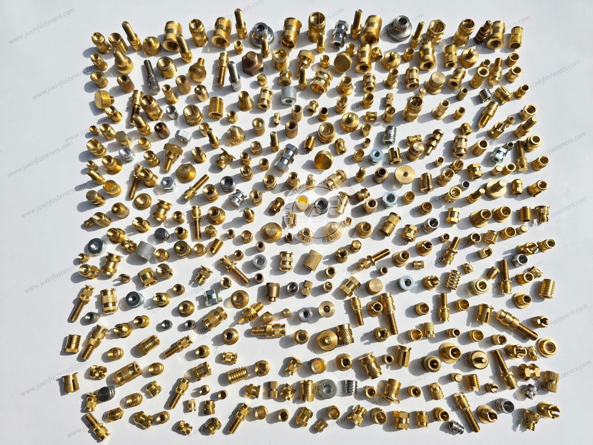
Brass is widely used for threaded inserts because suitable brass alloys can provide:
Good machinability
Stable thread production
Useful corrosion resistance in many environments
Suitable mechanical properties for many plastic assemblies
But “brass insert” is not a complete engineering specification.
The actual alloy must be controlled.
Depending on the project and market, brass materials can be specified according to applicable:
EN
ASTM
ISO
Customer material specifications
Equivalent material selection should be based on:
Chemical composition
Mechanical requirements
Machinability
Corrosion environment
Regulatory requirements
rather than relying only on a regional alloy trade name.
Environmental and product requirements increasingly influence brass selection.
Depending on the project, the customer may require:
Conventional machinable brass
Low-lead brass
Lead-free brass
Customer-approved alloy
This can affect:
Machining
Tool wear
Surface finish
Cost
Mechanical behavior
Therefore material substitution should be reviewed rather than treated as purely commercial.
A supplier should not claim that every brass insert automatically complies with every environmental requirement simply because brass is used.
If RoHS, REACH or customer-specific restricted-substance requirements apply, specify:
Material
Applicable requirement
Required documentation
Lot / project expectations
Environmental compliance should be verified against the supplied component and applicable requirement.
Stainless steel may be considered where:
Corrosion environment
Temperature
Mechanical requirements
Customer material specification
justify its use.
But:
Stainless Insert ≠ Automatically Better Insert.
Compared with brass, manufacturing behavior, cost, thread friction and installation characteristics can differ.
The complete application should determine material choice.
Steel inserts can provide useful mechanical performance and cost characteristics in suitable applications.
Surface treatment may be required depending on:
Corrosion environment
Appearance
Assembly requirements
But coating thickness and surface treatment must remain compatible with the thread and insert geometry.
Heat-set installation uses controlled heat to soften the thermoplastic around the insert.
A typical process is:
Insert Positioned → Controlled Heat Applied → Polymer Softens → Insert Moves Into Boss
→ Polymer Flows Around Retention Features → Cooling → Mechanical Interlock
The quality of the final joint depends on the process window.
Correct process temperature depends on:
Polymer
Insert geometry
Boss geometry
Equipment
Installation speed
Part design
Therefore a generic installation temperature should not be copied from one material to another.
Excessive heat can cause:
Polymer degradation
Boss distortion
Surface damage
Excessive material displacement
Poor insert position
Insufficient heat can result in:
High insertion force
Incomplete polymer flow
Weak retention
Boss cracking
Process development should identify the correct window.
For automated thermal insertion, useful process parameters may include:
Temperature
Insertion force
Displacement
Speed
Hold time
Final position
The exact monitoring strategy should match the application.
Ultrasonic insertion uses localized vibration energy to generate heat at the insert-polymer interface.
Potential advantages in suitable applications include:
Rapid installation
Localized heating
Compatibility with automated assembly
However, ultrasonic parameters must be developed for the actual:
Polymer
Insert
Boss
Equipment
Ultrasonic insertion can be highly effective.
But it is not universally superior.
Heat staking may be preferred in some applications because of:
Equipment availability
Geometry
Polymer
Process-control strategy
Production economics
The process should be selected by application.
Insert molding places the metal insert into the mold before polymer injection.
The plastic is then molded around the insert.
Potential advantages include:
Integrated manufacturing
No secondary insertion step
Strong geometric integration
But insert molding introduces its own engineering requirements.
The insert must remain correctly positioned during molding.
Important factors can include:
Mold holding feature
Insert geometry
Injection pressure
Polymer flow
Thread protection
Potential problems include:
Insert movement
Plastic entering the thread
Incorrect depth
Molding flash
Therefore:
Insert Molding ≠ Installation-Free Engineering.
It simply moves the fastening integration into the molding process.
| Decision Factor | Molded-In Insert | Post-Mold Thermal / Ultrasonic Insert |
|---|---|---|
| Installation timing | During molding | After molding |
| Secondary insertion | Eliminated | Required |
| Mold complexity | Higher | Generally lower |
| Insert-position control | Mold dependent | Installation equipment dependent |
| Risk of plastic in thread | Must be controlled during molding | Generally lower |
| Production flexibility | Tooling dependent | Often higher |
| Replacement / design change | More difficult | Potentially easier |
Neither approach is universally superior.
Some inserts are designed for mechanical press installation into suitable plastics.
These should be distinguished from inserts intended for heat or ultrasonic installation.
Press-in performance depends on:
Polymer
Hole
Interference
Insert geometry
Boss wall
Using a heat-set insert as a press-in insert without validation can create excessive boss stress.
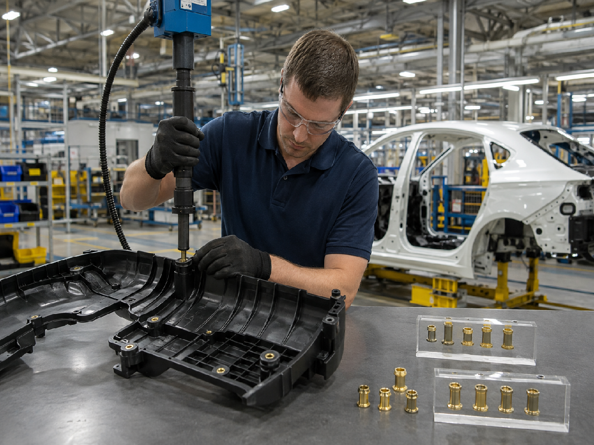
Two inserts with identical:
Thread
Length
Outside diameter
can perform differently if designed for different installation methods.
Therefore:
Same Dimensions ≠ Same Insert Function.
The RFQ should identify the intended installation process.
Threaded inserts can support suitable:
Instrument-panel components
Center consoles
Display housings
Infotainment systems
Interior brackets
Trim structures
HVAC components
Important considerations include:
Repeated service
Temperature
Polymer creep
vibration
noise / movement
packaging
But a threaded insert alone does not guarantee vibration-resistant assembly.
A metal insert provides a threaded attachment in the polymer.
It does not automatically prevent the mating screw from loosening.
If screw self-loosening is a concern, the engineer must consider:
Preload
Friction
Joint movement
Locking strategy
Thermal cycling
Therefore:
Insert Retention ≠ Screw Anti-Loosening.
When a machine screw is tightened into a threaded insert, torque is an installation input.
The resulting preload depends on factors including:
Thread friction
Under-head friction
Screw coating
Insert material
Lubrication
Bearing interface
Therefore:
Torque ≠ Preload.
And:
Same Torque + Different Friction ≠ Same Preload.
Even if the metal thread can withstand high torque, the surrounding plastic boss may not.
Potential failure sequence:
Higher Tightening Torque → Higher Joint Load → Insert Rotation / Pull-Out / Boss Stress → Plastic Failure
Therefore:
Metal Thread Capacity ≠ Plastic Joint Capacity.
Threaded inserts can be used in suitable:
ECU housings
Sensor modules
Infotainment electronics
Power-electronics housings
BMS-related enclosures
Control modules
But:
Mechanical Fastening ≠ Electrical Safety.
The insert does not itself establish:
Electrical insulation
Creepage
Clearance
Grounding
EMI / EMC
High-voltage qualification
These functions must be engineered separately.
Brass is electrically conductive.
But:
Conductive Material ≠ Qualified Electrical Connection.
If an insert is intentionally used as part of:
Grounding
Bonding
Current path
the electrical interface requires separate design and validation.
Electric vehicles increase the number of electronic and polymer assemblies, creating additional opportunities for engineered inserts.
Potential locations can include selected:
Control modules
Electronic housings
Thermal-management components
Interior electronics
Non-structural battery-related components
However:
Fastener ≠ Battery-System Safety Qualification.
High-voltage, fire, crash, sealing and thermal requirements belong to the complete battery or electrical system.
If an insert is used near a battery enclosure or sealed boundary, the engineer should separately evaluate:
Mechanical load
Sealing
Electrical insulation
corrosion
temperature
crash / structural requirements where applicable
A threaded insert should never be assumed to provide IP protection merely because it creates a threaded attachment.
If a threaded insert penetrates a sealed enclosure:
Threaded Insert ≠ Automatic IP Seal.
Sealing may require:
Gasket
O-ring
Sealing washer
Sealant
Molded sealing feature
depending on the design.
Automotive components can experience repeated temperature changes.
Metal inserts and polymers have different coefficients of thermal expansion.
Thermal cycling can therefore affect:
Interface stress
Insert retention
Boss stress
Clamp load
Long-term dimensional behavior
This becomes more important when:
Temperature range is large
Polymer creep is significant
Insert and boss geometry are highly constrained
A room-temperature pull-out test can provide useful information.
But it does not automatically predict performance after:
Thermal aging
Moisture exposure
Chemical exposure
Vibration
Repeated service
Thermal cycling
Validation should match the actual application.
Where inserts are installed in nylon components, moisture condition can affect polymer behavior.
Therefore testing only dry-as-molded parts may not represent all service conditions.
Engineers should determine whether moisture-conditioned testing is relevant to the application.
Depending on location, plastic components can encounter:
Oils
Coolants
Cleaning chemicals
Automotive fluids
Chemical compatibility belongs primarily to the polymer system, but changes in polymer properties can also affect insert retention.
The complete material system should therefore be considered.
The original article described inserts as requiring “lifelong metal fatigue endurance.”
That is too broad.
Threaded-insert durability depends on the actual load path.
In many insert applications, the more relevant risks may be:
Polymer fatigue
Boss cracking
Insert movement
Screw loosening
Interface wear
Testing should reproduce the expected failure mechanism.
Not every threaded insert requires the same vibration test.
Validation should be based on:
Application
Load
Assembly location
Customer specification
Risk
More testing is not automatically better if the test does not represent the real failure mode.
Potential causes include:
Insufficient engagement
Incorrect knurl geometry
Oversized pilot hole
Weak polymer
Poor installation
Excessive axial load
High temperature
Boss failure
The solution should address the controlling interface.
Potential causes include:
Insufficient torque-retention geometry
Incorrect hole
Poor polymer flow around knurls
Installation error
Excessive tightening torque
Increasing insert length alone may not solve rotational failure.
Potential causes include:
Pilot hole too small
Boss wall too thin
Insert OD too large
Incorrect insertion method
Insufficient heat
Brittle polymer condition
Excessive press force
Remember:
More Installation Force ≠ Better Installation.
Potential causes can include:
Excessive tightening torque
Residual installation stress
Thermal cycling
chemical exposure
insufficient boss geometry
long-term material behavior
A part that survives assembly can still fail later.
Potential causes include:
Insufficient thread engagement
Incorrect screw
Excessive tightening
Thread damage
Material mismatch
This failure should be distinguished from insert rotation or pull-out.
Potential causes include:
Poor depth control
Inconsistent installation temperature
Part dimensional variation
Incorrect fixture
excessive or insufficient insertion energy
Final insert position can affect assembly stack-up.
This can be especially relevant to insert molding.
Potential causes include:
Inadequate thread protection
Poor mold location
Insert movement
molding-process variation
The solution belongs to mold and insert interface design.
A common reaction to insert failure is:
“Use a larger insert.”
That can be wrong.
Instead use:
Failure Mode → Polymer → Boss → Hole → Insert Geometry → Installation → Mating Screw → Load → Environment → Corrective Action
For example:
Pull-Out Failure → Evaluate Axial Load / Engagement / Boss / Polymer
Torque-Out Failure → Evaluate Knurl / Polymer Flow / Hole / Installation
Boss Cracking → Evaluate Interference / Heat / Wall Thickness / Polymer
Screw Loosening → Evaluate Threaded Joint / Preload / Friction / Movement
This is more effective than simply increasing fastener size.
Depending on geometry, material and production volume, threaded inserts can be manufactured through combinations of:
Precision turning
CNC machining
Cold forming for suitable designs
Thread cutting
Thread forming
Knurling
Grooving
Slotting
Chamfering
Surface treatment
The correct route depends on:
Geometry
Tolerance
Material
Volume
Cost
The old article overemphasized CNC technology as though CNC itself guaranteed performance.
It does not.
A CNC-machined insert can still be wrong if:
Knurl geometry is unsuitable
Material is incorrect
Thread is out of specification
Boss design is poor
Installation is uncontrolled
Likewise, a properly engineered high-volume forming process can produce excellent components.
Therefore:
Manufacturing Process Must Match Product Geometry and Volume.
Producing critical features in a controlled setup can help manage:
Concentricity
Position
Repeatability
But claims such as “perfect concentricity” or “virtually eliminating axial failure” are not technically appropriate.
Dimensional control should be defined by:
Drawing tolerance
Process capability
Inspection plan
and functional performance must still be validated in the actual plastic assembly.
A threaded insert may have:
Excellent internal thread
Poor external knurl
or:
Excellent knurl
Damaged internal thread
Both interfaces matter.
Quality control should therefore separate:
Thread Quality
from:
Insert-to-Polymer Retention Geometry
Depending on the drawing, inspection may include:
Overall length
Outside diameter
Thread
Lead chamfer
Knurl dimensions
Groove geometry
Flange dimensions
Concentricity where functionally required
Visual condition
Inspection requirements should match the drawing rather than adding unnecessary controls.
Functional validation can include application-specific:
Pull-out
Torque-out
Installation force / process monitoring
Mating-screw testing
Assembly torque
Thermal conditioning
Environmental conditioning
But:
More Testing ≠ Better Engineering.
Tests should represent the real application.
Testing the insert alone cannot establish installed performance.
Where pull-out or torque-out is important, testing should use a representative substrate with controlled:
Polymer
Grade
Boss
Hole
Installation process
Therefore:
Insert Drawing Compliance ≠ Installed Joint Validation.
Prototype parts can behave differently from final molded components.
Differences may include:
Polymer grade
Reinforcement
Mold process
Fiber orientation
Moisture
Hole geometry
Therefore:
Prototype Material ≠ Production Material.
Final validation should use production-representative components where the application requires it.
Procurement and supplier-development teams should evaluate threaded insert suppliers beyond unit price.
Important controls can include:
Drawing and revision control
Material control
Thread inspection
External geometry
Knurl consistency
Dimensional inspection
Production process
Surface condition
Lot control where required
Packaging
Functional testing where specified
Change control
The control plan should match product and application risk.
The old article used “zero-defect quality management.”
For a professional OEM-facing technical page, a stronger engineering position is:
Define Critical Characteristics → Control Manufacturing Process → Inspect to Requirement → Validate Functional Performance → Monitor Production Consistency
This is more credible to supplier-quality engineers than unsupported “zero defect” marketing language.
Automation can improve:
Throughput
Repeatability
Data collection
Handling
But:
Automation ≠ Automatic Quality Assurance.
Automated production still requires:
Process control
Tool monitoring
Inspection
Maintenance
Material control
The correct manufacturing strategy depends on volume and geometry.
Low-volume development parts may use a different manufacturing route from mass production.
For example:
Prototype → CNC Machining
may later become:
Production → Optimized Turning / Forming / Automated Secondary Operations
where technically appropriate.
Therefore:
Prototype Process ≠ Production Process Qualification.
A production change should be evaluated before approval.
Threaded inserts are often sourced by:
Thread
OD
Length
alone.
This is risky.
Two inserts with identical nominal dimensions can differ significantly in:
Material
Knurl geometry
Groove depth
Lead geometry
Thread quality
Surface condition
Installation behavior
Therefore:
Same Dimensions ≠ Functional Equivalence.
For threaded inserts, the external retention geometry can be just as important as the internal thread.
A second-source supplier should not modify:
Knurl angle
Knurl direction
Groove
Undercut
Lead geometry
without engineering review where those features affect performance.
A visually similar insert is not necessarily functionally equivalent.
Changing from one brass alloy to another may affect:
Machinability
Mechanical properties
Corrosion
Regulatory compliance
Cost
Changing from brass to steel or stainless can affect even more variables.
Therefore:
Same Geometry + Different Material ≠ Automatic Equivalent.
For important applications, qualification should compare:
Installation behavior
Final position
Pull-out
Torque-out
Mating screw
Boss condition
in production-representative plastic.
This is more meaningful than comparing metal inserts on a table.
Procurement should not compare threaded inserts only by piece price.
A more useful model is:
Total Installed Cost = Insert Price + Installation + Tooling + Inspection + Scrap + Rework + Plastic-Part Damage + Assembly Time + Maintenance + Logistics + Supply Risk
A cheaper insert can become expensive if it causes:
Boss cracking
Installation rejects
Tooling problems
Insert rotation
Field service failures
A heat-set insert introduces a secondary assembly operation.
A molded-in insert can eliminate that operation but may increase:
Mold complexity
Insert handling
Molding-process requirements
The lowest insert price therefore does not identify the lowest-cost assembly.
Standard inserts can be appropriate where:
Existing geometry fits the boss
Required thread is available
Installation process is established
Functional performance is sufficient
Custom inserts may be justified when the assembly requires:
Special length
Restricted OD
Custom knurl
Special flange
Special lead geometry
Unique thread
Material requirement
Automated feeding geometry
Packaging constraint
A custom insert can potentially be produced by different processes depending on:
Geometry
Material
Tolerance
Annual volume
DFM should determine the manufacturing route.
This can significantly affect production cost.
The same engineering principles apply to selected applications in:
Potential uses include:
Plastic housings
Communication modules
Enclosures
Serviceable electronic assemblies
Potential uses include:
Polymer housings
Control equipment
Electrical modules
Insulating structures
Potential uses include:
Electronic modules
Cooling-system components
Serviceable polymer housings
Equipment enclosures
Potential uses include:
Inverter housings
Converter components
Control modules
Cooling assemblies
Potential uses include:
Sensor housings
Control modules
Polymer covers
Serviceable assemblies
Threaded inserts can be used in suitable equipment housings and assemblies.
However, material and finished component selection must follow the specific regulatory, cleaning and application requirements.
A generic insert should not be described as automatically medical-qualified.
Potential applications include:
Housings
Displays
Electronic modules
Repeatedly serviced components
The same rules for polymer, boss design and installation remain relevant.
For an accurate technical and commercial evaluation, provide:
2D drawing
3D model where available
Part number
Drawing revision
Application
Internal thread
Mating screw
Insert length
Insert outside diameter
Flange requirement
Knurl geometry where defined
Insert material
Parent polymer
Exact polymer grade where known
Reinforcement / filler
Boss diameter
Boss wall thickness
Pilot-hole diameter
Hole depth
Installation method
Installation equipment where relevant
Required pull-out performance
Required torque-out performance
Tightening torque where defined
Operating temperature
Thermal cycling requirement
Moisture exposure
Chemical exposure
Annual volume
Sample quantity
Validation requirement
Applicable ISO, DIN, EN, ASTM, SAE, ASME/ANSI or customer specifications
Provide:
Polymer grade
Pilot-hole geometry
Boss drawing
Insert depth
Installation equipment
Existing process parameters if already validated
Do not copy thermal settings from another polymer without evaluation.
Provide:
Polymer
Boss
Insert
Ultrasonic equipment information where relevant
Production cycle requirement
Existing validated parameters if applicable
The insert supplier and assembly engineer should evaluate the interface together.
Provide:
Molded component drawing
Mold location strategy
Polymer
Injection conditions where relevant
Insert retention during molding
Thread-protection requirement
This helps identify whether special holding or sealing features are required.
A controlled sourcing process can follow:
Application → Polymer → Boss → Thread → Load → Insert Geometry → Installation Method → Material → Prototype
→ Installation Trial → Pull-Out / Torque-Out Validation → Assembly Validation → Approval → Production
For custom inserts:
Drawing → DFM → Manufacturing Route → Sample → Dimensional Inspection → Installation Trial → Functional Validation → Production Approval
For second sourcing:
Approved Drawing → Material → Thread → Knurl Geometry → Manufacturing Process → Sample → Installation Comparison
→ Functional Testing → Assembly Validation → Approval
Before specifying a threaded insert for an automotive plastic component, answer these questions.
Do not specify only “plastic.”
Identify the exact grade where possible.
Glass fiber or other reinforcement can change:
Flow
Stiffness
brittleness
boss behavior
installation window
Determine whether the controlling requirement is:
Pull-out
Torque-out
Clamp load
Repeated service
Combination loading
Choose intentionally between:
Heat staking
Ultrasonic insertion
Insert molding
Press-in installation
Another validated process
Review:
OD
Wall thickness
Height
Pilot hole
Hole depth
Nearby ribs
Define:
Thread
Screw material
Coating
Engagement
Tightening requirement
Evaluate:
Temperature
Thermal cycling
Moisture
Chemicals
Vibration
If yes, consider:
Thread durability
Screw accessibility
Number of expected service cycles
Boss long-term behavior
Choose tests based on actual failure risk.
Do not use a generic test package without understanding the application.
This page should function as the dedicated Threaded Inserts for Plastic / Automotive Plastic Insert Engineering resource.
Recommended internal links include:
Automotive Self-Tapping Screws → direct threading into plastics vs threaded inserts
Lightweight Automotive Fasteners → automotive material-selection strategy
Automotive Fastener Selection Guide → overall fastening technology selection
Automotive Fastener Quality Control → OEM inspection and supplier qualification
Electrical Equipment Fasteners → plastic and electronic equipment fastening
Telecom Equipment Fasteners → PCB, enclosure and telecom fastening
Fasteners for Aluminum → threaded attachment strategies for aluminum components
Stainless Steel Fasteners → stainless material and corrosion selection
Custom Fastener Manufacturing → custom insert manufacturing and DFM
Industrial Fastener Solutions → overall industrial fastening technology selection
Use the existing indexed JUXIN FASTENERS URL when implementing these internal links.
There is no universal best insert. Selection depends on polymer, boss geometry, thread, load, installation method, temperature and service requirements.
Brass inserts are widely used in suitable plastic assemblies because of their machinability and useful mechanical characteristics, but the complete insert-to-polymer system must be validated.
The insert itself may be similar or specifically designed for the process, but the installation energy is delivered differently.
Heat-set installation uses controlled thermal input, while ultrasonic installation uses localized vibration energy.
Not automatically. Performance depends on polymer, insert geometry, boss and installation.
Pull-out measures resistance to axial extraction. Torque-out measures resistance to rotation of the insert within the polymer.
No. They are different failure modes.
No. Insert torque-out and screw self-loosening are different mechanisms.
Not automatically. The surrounding plastic boss can still control joint strength.
Potentially, but a stronger screw does not automatically increase the strength of the insert-to-plastic interface.
Potential causes include unsuitable knurl geometry, oversized holes, poor installation, insufficient polymer flow or excessive tightening torque.
Possible causes include inadequate engagement, unsuitable insert geometry, weak polymer, poor boss design, installation problems or excessive axial load.
Potential causes include a small pilot hole, excessive interference, inadequate heating, thin boss walls, brittle polymer or excessive installation force.
Not automatically. Different polymers and grades can require different boss geometry, hole size and installation parameters.
It should not be assumed. Reinforcement changes polymer behavior and can affect installation and retention.
They can be advantageous where a reusable machine-screw thread is required, but the complete joint and expected service cycles should be evaluated.
No. Brass is electrically conductive.
Only if the complete electrical connection has been intentionally designed and validated for that purpose.
No. A threaded insert does not automatically provide an IP-rated seal.
The required tolerance should follow the applicable drawing and thread specification.
For ISO metric threads, a class such as 6H may be specified where appropriate, but it does not define the complete insert performance.
No. Material, thread, knurl geometry, installation behavior and functional performance should also be evaluated.
Send the insert drawing, plastic component drawing, polymer, boss geometry, mating screw, installation method, performance requirements, environment and annual volume.
A threaded insert should never be selected as an isolated metal component.
The correct engineering sequence is:
Application → Polymer → Boss Geometry → Pilot Hole → Insert Geometry → Installation Process → Mating Screw → Load → Environment → Validation
The key principles are:
Strong Insert ≠ Strong Plastic Joint
Same Polymer Name ≠ Same Finished Joint Performance
Pilot Hole ≠ Clearance Hole
Aggressive Knurl ≠ Automatically Stronger Joint
Pull-Out ≠ Torque-Out
Torque-Out ≠ Screw Self-Loosening
Strong Internal Thread ≠ Strong Installed Insert Joint
Stronger Screw ≠ Stronger Plastic Joint
More Installation Energy ≠ Better Installation
More Installation Force ≠ Better Installation
Initial Pull-Out Strength ≠ Lifetime Joint Performance
Insert Retention ≠ Screw Anti-Loosening
Torque ≠ Preload
Conductive Material ≠ Qualified Electrical Connection
Threaded Insert ≠ Waterproof Interface
CNC Machining ≠ Automatically Better Insert
Automation ≠ Automatic Quality Assurance
Prototype Process ≠ Production Process Qualification
Material Substitution Can Be an Engineering Change
Same Dimensions ≠ Functional Equivalence
For engineers, the objective is to create a predictable load-transfer system between the mating screw, metal insert and polymer component.
For procurement and supplier-development teams, the objective is to source an insert that remains functionally equivalent after material,
manufacturing process, supplier or production volume changes.
JUXIN FASTENERS supports selected automotive, electronics, telecom, electrical equipment and industrial OEM projects with:
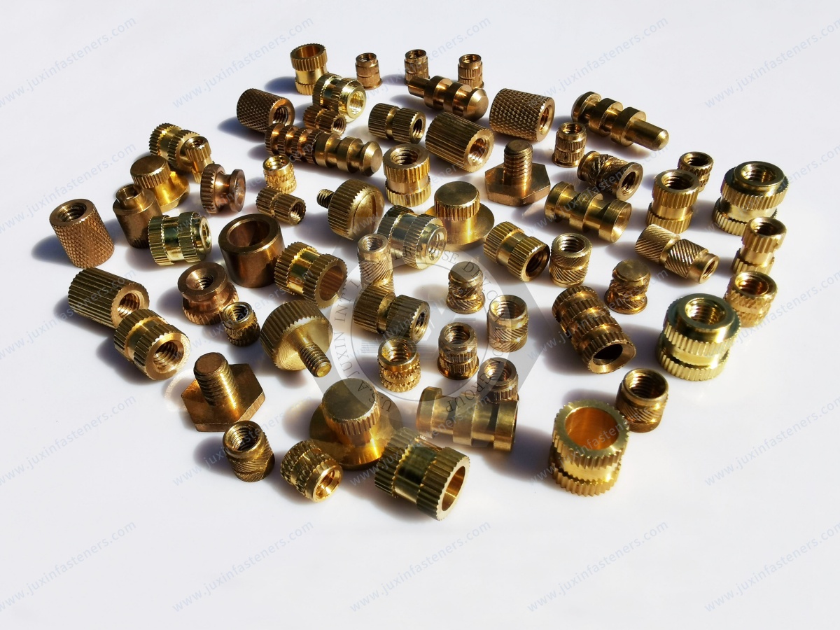
Brass threaded inserts
Knurled inserts for plastic
Heat-set inserts
Ultrasonic inserts
Molded-in inserts
Threaded metal inserts
Stainless steel inserts
Steel inserts
Drawing-based custom inserts
Precision machined fastening components
OEM fastening components
For an effective RFQ, provide:
2D Drawing + 3D Model + Part / Revision + Application + Internal Thread + Mating Screw + Insert Geometry + Material + Parent Polymer
+ Boss Geometry + Pilot Hole + Installation Method + Pull-Out / Torque-Out Requirement + Temperature + Environment + Annual Volume
For automotive plastic components, sending both the insert drawing and the mating plastic component / boss drawing provides a much stronger
basis for technical review than sending the insert dimensions alone.
JUXIN FASTENERS
Threaded Inserts for Plastic | Brass Inserts | Heat-Set Inserts | Custom OEM Fasteners
Email: info@juxinfasteners.com
Website: www.juxinfasteners.com
Contact Us
Tel.:
+86 020 8621 0320
+86 020 3121 6067
E-mail:
Technical Support:
Navigation
SEND INQUIREY



