
Call Us
+86 136 6007 9809
Call Us
+86 136 6007 9809

May. 19, 2026
Aerospace equipment combines lightweight structures, thin-wall components, aluminum alloys, composites, electronic enclosures,
precision instruments and serviceable assemblies that often require durable threaded attachment points.
Threaded inserts can provide those attachment points where the parent structure alone cannot provide sufficient thread engagement,
where repeated maintenance would damage the parent thread, or where a replaceable threaded interface is preferred.
Potential applications include selected:
Avionics enclosures
Instrument housings
Sensor assemblies
Interior equipment
Access panels
Electronic modules
Cable-management structures
Composite components
Aluminum housings
Ground-support equipment
Test equipment
Maintenance fixtures
Other drawing-controlled aerospace components
However, aerospace insert selection cannot be reduced to:
“Choose a high-strength insert for a high-strength application.”
The installed joint is a system:
Parent Material + Insert Material + Insert Geometry + Installation Method + Mating Fastener + Thread Engagement
+ Preload + Temperature + Vibration + Corrosion + Serviceability + Validation
The central engineering principle is:
Strong Insert ≠ Strong Installed Joint.
JUXIN FASTENERS supports selected drawing-based threaded inserts, precision fasteners and custom fastening components for aerospace equipment,
aviation maintenance equipment, electronics, industrial systems and other OEM applications.
For flight-critical, primary structural, propulsion, flight-control or other safety-critical aerospace locations, fastener selection must follow the aircraft,
engine, spacecraft, OEM or program-specific approved specification and qualification process. A standard commercial threaded insert should never be assumed to be qualified for such applications.
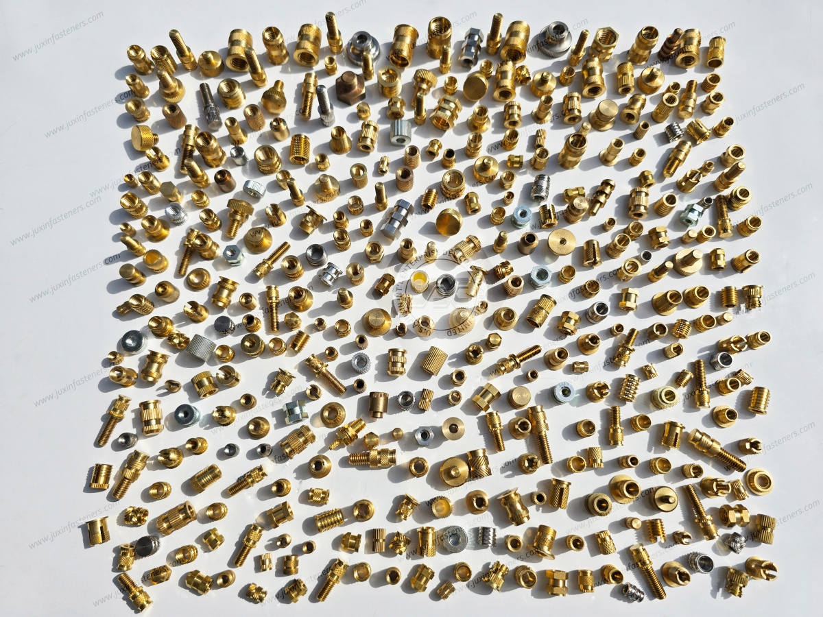
A threaded insert is a separate component installed into a parent structure to create or reinforce an internal thread.
Depending on the parent material and application, inserts can provide:
Reusable internal threads
Improved thread durability
Repair of damaged threaded locations
Load transfer into lightweight parent materials
Replaceable threaded interfaces
Assembly standardization
Serviceability
Threaded inserts may be manufactured from:
Stainless steel
Alloy steel
Titanium
Aluminum
Brass or copper alloys for suitable non-critical applications
Other customer-specified materials
But the correct material cannot be selected independently from the parent structure.
Lightweight aerospace engineering often reduces material thickness and replaces heavier structures with:
Aluminum
Titanium
Magnesium in suitable designs
Engineering polymers
Fiber-reinforced composites
Sandwich structures
Thin-wall housings
These materials can create a basic fastening problem:
The parent structure may be adequate for the component, but not ideal for repeated direct threading.
A threaded insert can separate these two functions.
The parent material provides the structure.
The insert provides the threaded interface.
Installing a metal insert does not automatically make the joint stronger.
The final load path may include:
Mating Screw → Insert Internal Thread → Insert Body → Insert Retention Interface → Parent Material → Surrounding Structure
The joint can fail at any point in this chain.
Possible failure modes include:
Mating screw failure
Internal thread stripping
Insert pull-out
Insert rotation
Parent-material bearing failure
Local cracking
Composite delamination
Boss failure
Fatigue damage
Joint slip
Preload loss
Therefore:
Insert Strength ≠ Assembly Strength.
A useful engineering sequence is:
Application → Parent Material → Load Path → Thread → Insert Type → Material → Installation Method → Mating Fastener → Environment → Validation
Procurement should not begin with material or price before these variables are understood.
The same insert can behave very differently in:
Aluminum
Titanium
Stainless steel
Thin steel
Engineering plastic
Carbon-fiber composite
Glass-fiber composite
The parent material controls important characteristics such as:
Bearing strength
Thread support
Installation behavior
Local deformation
Fatigue response
Galvanic compatibility
Therefore:
Same Insert + Different Parent Material ≠ Same Joint Performance.
Aluminum is widely used in aerospace equipment because of its favorable strength-to-weight characteristics and manufacturability.
Potential insert applications include:
Avionics housings
Instrument structures
Access covers
Electronic enclosures
Lightweight brackets
Ground-support equipment
A threaded insert can be useful when the aluminum parent material does not provide sufficient:
Thread engagement
Wear resistance
Service-cycle durability
Repairability
But aluminum joint design requires more than selecting a strong insert.
If a high-strength screw is installed into an insert retained by relatively soft aluminum, the parent aluminum may become the controlling failure point.
The designer must consider:
Insert engagement
Parent-material thickness
Edge distance
Bearing stress
Installation geometry
Applied preload
Therefore:
Stronger Screw ≠ Stronger Parent Material.
The lowest-density insert is not automatically the best aerospace solution.
| Insert Material | Potential Engineering Advantage | Important Consideration |
|---|---|---|
| Aluminum | Low density | Thread strength, wear, parent compatibility |
| Stainless steel | Corrosion resistance, durable threads | Density, galling, galvanic interaction |
| Alloy steel | High mechanical capability | Corrosion protection, material compatibility |
| Titanium | High strength-to-weight potential | Cost, galling, galvanic and manufacturing considerations |
| Brass | Machinability and useful corrosion behavior | Density, strength and application suitability |
Material selection should follow the joint requirement.
A small reduction in insert mass may have little impact on total assembly weight if it requires:
Larger boss
Additional reinforcement
Larger surrounding structure
Additional corrosion isolation
Therefore:
Lower Insert Density ≠ Automatically Lower System Mass.
Weight should be evaluated at assembly level.
Titanium can be attractive where high specific strength, corrosion behavior and weight are important.
Potential applications should be evaluated according to the approved design requirements.
Titanium introduces considerations such as:
Material grade
Thread behavior
Galling
Mating fastener material
Surface treatment
Lubrication
Galvanic interaction
Manufacturing cost
Therefore:
Titanium ≠ Automatic Aerospace Upgrade.
A titanium insert can be technically unnecessary or even introduce new interface problems if selected only because the application is aerospace.
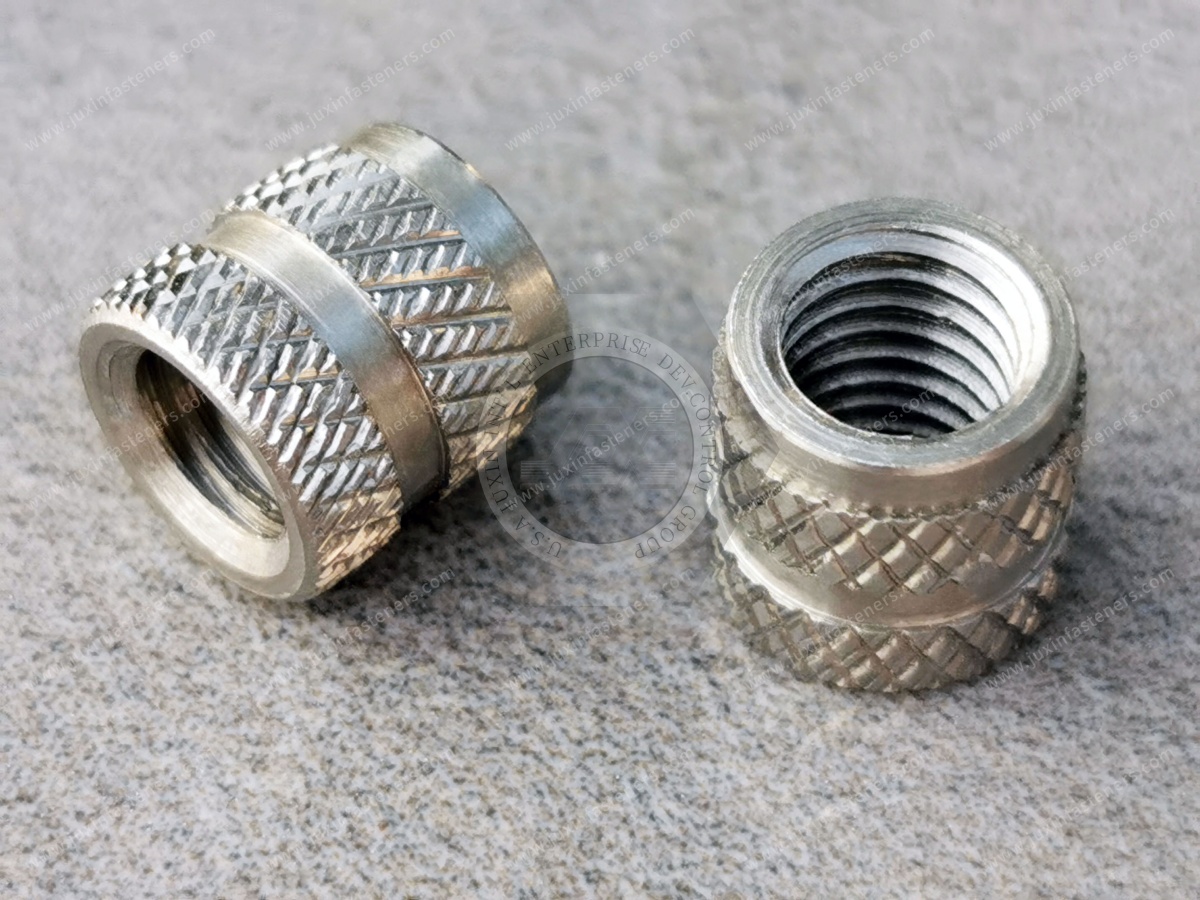
Stainless steel can provide:
Durable internal threads
Useful corrosion resistance
Mechanical stability
in suitable applications.
Common stainless families may be considered depending on customer specification and environment.
However:
Stainless Steel ≠ Corrosion-Proof.
And:
316 Stainless Steel ≠ Automatically Best for Aerospace.
The environment, mating material and joint architecture determine suitability.
Alloy steel inserts can provide useful mechanical performance where high strength and durable threads are required.
Depending on the environment, the insert may require a controlled surface treatment.
The coating specification can affect:
Corrosion resistance
Dimensions
Thread fit
Friction
Galvanic interaction
Therefore:
Coating Name ≠ Complete Coating Specification.
Brass can be appropriate for selected:
Instruments
Electronic housings
Ground-support equipment
Non-critical adjustment components
Polymer assemblies
where the engineering requirements support its use.
But a brass insert should not be marketed generically as an “aerospace-grade structural insert.”
Material suitability must be determined by:
Load
Environment
Temperature
Parent material
Program specification
Specifying a recognized titanium, aluminum, steel or stainless grade does not automatically make the finished insert compliant with an aerospace program.
Qualification may also depend on:
Material source
Heat condition
Manufacturing process
Dimensions
Threads
Surface treatment
Inspection
Traceability
Testing
Customer approval
Therefore:
Material Grade ≠ Finished Component Compliance.
The internal thread is one of the most important functional interfaces.
Depending on the project, threads may follow applicable:
ISO metric
Unified inch
ASME/ANSI
Customer-specific
Aerospace program-specific requirements
The drawing should define the actual thread requirement.
An RFQ stating:
“Need M5 aerospace insert”
or:
“Need 1/4-28 insert”
does not define the component.
The supplier may still need:
Thread series
Tolerance / class
Insert OD
Insert length
External retention geometry
Material
Surface treatment
Installation method
Parent material
Load requirement
Therefore:
Correct Thread ≠ Correct Insert.
A threaded insert has at least two critical interfaces:
Mating Fastener ↔ Insert Thread
and:
Insert ↔ Parent Structure
The first can be strong while the second is weak.
Therefore:
Strong Internal Thread ≠ Strong Installed Insert Joint.
This distinction is particularly important in lightweight structures.
Thread engagement must be sufficient for the required load, but simply increasing engagement does not guarantee a better joint.
The controlling failure mode may move from:
Internal thread stripping
to:
Insert pull-out
Parent-material failure
Mating screw failure
Engineering should identify the actual load path rather than maximize one dimension.
For a threaded aerospace joint:
Torque is an installation input.
Preload is the tensile force generated in the fastener.
The relationship is strongly affected by friction.
Factors include:
Thread finish
Insert material
Screw coating
Lubricant
Under-head interface
Surface condition
Therefore:
Torque ≠ Preload.
And:
Same Torque + Different Friction ≠ Same Preload.
A second-source insert may have the same:
Material
Thread
Dimensions
but a different surface condition.
That can change friction at the mating thread.
Therefore:
Same Dimensions + Different Surface Condition ≠ Same Tightening Behavior.
This is one reason aerospace sourcing requires controlled revision and change management.
Stainless steel and titanium threaded interfaces can be susceptible to galling under certain combinations of:
Material
Surface condition
Load
Speed
Temperature
Lubrication
Galling can result in:
Increased friction
Thread damage
Seizure
Torque instability
But the solution should not be a generic lubricant recommendation.
A lubricant, dry-film system or coating can alter:
Friction
Preload
Assembly torque
Surface interaction
Therefore:
Lubricant ≠ Independent Add-On.
If lubrication is specified, it should be treated as part of the approved joint configuration.
Applying the same tightening torque after changing from a dry interface to a lubricated interface can produce a different preload.
Therefore:
Dry Torque ≠ Lubricated Torque.
Any lubrication change should be reviewed against the assembly specification.
Threaded inserts can use different retention mechanisms depending on the parent material.
Examples may include:
Internal / external thread systems
Mechanical locking features
Knurled retention
Interference
Expansion
Swaging
Molded-in geometry
Heat-set geometry for suitable polymers
Customer-specific locking structures
These should not be treated as interchangeable.
Knurled inserts can be useful in suitable:
Polymer components
Instrument housings
Adjustment components
Other designed interfaces
But the original article incorrectly treated knurling as a general aerospace anti-loosening technology.
Knurl geometry usually performs a specific interface function.
Depending on the design, it can contribute to:
Grip
Rotation resistance
Retention
Manual adjustment
But:
Knurl ≠ Automatic Vibration Lock.
These are two different failure modes.
Insert Rotation
The insert rotates relative to its parent material.
Screw Self-Loosening
The mating screw rotates relative to the insert.
Therefore:
Insert Torque-Out ≠ Screw Anti-Loosening Performance.
A high torque-out value does not prove that the threaded joint will resist self-loosening under vibration.
The primary function of a threaded insert is usually to provide or reinforce a threaded interface.
If the assembly requires resistance to self-loosening, the joint may require separate consideration of:
Preload
Joint stiffness
Friction
Locking strategy
Vibration
Thermal cycling
Service requirements
Do not assume the insert itself solves these issues.
The original article suggested combining inserts with locking washers and other devices as a generic aerospace solution.
This is too broad.
A standard washer may provide:
Bearing support
Load distribution
Surface protection
but:
Washer ≠ Automatic Anti-Loosening Device.
The locking strategy must match the joint.
Even a correctly selected locking element cannot compensate for an incorrectly designed or assembled joint.
Therefore:
Locking Feature ≠ Correct Preload.
The complete threaded joint remains important.
Aerospace equipment can experience vibration from sources such as:
Engines
Rotating equipment
Aerodynamic loading
Vehicle movement
Ground operations
Launch environments in applicable space programs
But vibration requirements vary dramatically by application.
A fastener for ground-support equipment does not require the same qualification as a flight-critical aircraft or spacecraft joint.
Testing should follow the actual:
Program
Component
Installation location
Customer specification
Risk
Therefore:
Passing One Vibration Test ≠ Universal Aerospace Approval.
Cyclic loading can affect:
Mating screw
Insert
Parent material
surrounding structure
The controlling fatigue location depends on the load path.
A supplier should not claim “lifetime fatigue resistance” without defined:
Load
Cycles
Environment
Joint configuration
Acceptance criteria
Increasing static strength does not automatically increase fatigue performance.
Fatigue can be influenced by:
Geometry
Stress concentration
Surface condition
preload
load amplitude
installation damage
Therefore:
Higher Strength ≠ Automatically Better Fatigue Performance.
Aerospace equipment can experience wide temperature ranges depending on:
Aircraft location
altitude
electronics heat generation
engine proximity
external exposure
space environment
Temperature can affect:
Material strength
friction
preload
thermal expansion
parent-material behavior
The exact operating range should therefore be provided in the RFQ.

Different materials expand at different rates.
For example, an insert and an aluminum, polymer or composite parent structure can respond differently during thermal cycling.
This may affect:
Contact pressure
retention
preload
local stress
Therefore:
Room-Temperature Fit ≠ Full-Temperature Joint Validation.
Spacecraft and high-vacuum equipment introduce additional requirements.
Potential concerns can include:
Material selection
Lubricants
Coatings
Outgassing
temperature
vacuum compatibility
A standard aerospace or industrial insert should not automatically be described as vacuum-compatible.
Therefore:
Aerospace Fastener ≠ Space-Qualified Fastener.
Spacecraft launch, orbital operation and re-entry can impose highly specialized mechanical and environmental requirements.
JUXIN FASTENERS should not represent standard threaded inserts as automatically suitable for:
Launch-critical joints
Spacecraft primary structures
Propulsion systems
Re-entry-critical structures
without customer-approved specifications and qualification.
Threaded inserts may be useful in selected avionics and electronic equipment for:
Enclosure assembly
Access covers
Internal brackets
Sensor modules
serviceable components
Important engineering factors can include:
Weight
vibration
temperature
corrosion
serviceability
electrical architecture
But:
Mechanical Fastening ≠ Electrical Safety.
Metal inserts may be electrically conductive.
That does not mean they automatically provide a qualified:
Ground
Bond
Current path
EMI connection
Electrical function must be intentionally designed and validated.
Therefore:
Conductive Material ≠ Qualified Electrical Connection.
A metal insert may be part of an enclosure interface, but EMI / EMC performance belongs to the complete system.
Factors can include:
Enclosure
Contact surfaces
Gaskets
coating
joint spacing
grounding architecture
The fastener alone does not define system performance.
Composite structures require special attention because they do not behave like isotropic metals.
Potential concerns can include:
Local crushing
bearing
delamination
edge distance
fiber orientation
galvanic interaction with carbon fiber
insert installation damage
Therefore:
Composite ≠ Lightweight Metal.
A threaded insert validated in aluminum should not automatically be transferred to carbon-fiber composite.
Carbon-fiber composites can create galvanic concerns when coupled with certain metals in the presence of an electrolyte.
Insert selection may therefore require evaluation of:
Insert material
isolation
coating
sealant
moisture
joint geometry
The complete material couple matters.
An insert can resist corrosion itself while still contributing to galvanic attack of the surrounding structure.
Therefore:
Corrosion-Resistant Insert ≠ Corrosion-Resistant Joint.
For mixed-material aerospace assemblies, evaluate:
Insert Material + Parent Material + Mating Fastener + Coating + Electrolyte Exposure + Area Ratio + Joint Geometry
not simply the corrosion resistance of each component individually.
Depending on material and customer requirements, surface treatment can be used for functions such as:
Corrosion protection
friction control
wear behavior
electrical interface
appearance
Possible processes vary widely by substrate and program.
No coating should be selected merely because it is commonly described as “aerospace coating.”
A complete specification may need to define:
Coating system
thickness
conversion layer
topcoat
friction
color
corrosion requirement
applicable standard
Therefore:
Coating Name ≠ Coating Performance.
The old article stated a generic requirement of more than 800 hours of salt-spray resistance for harsh aerospace environments.
That should not be used as a universal engineering requirement.
Salt-spray testing can be useful for defined coating evaluation.
But:
Salt Spray Hours ≠ Field Service Life.
Real aerospace exposure may involve combinations of:
Humidity
wet/dry cycles
chlorides
temperature
fuels or fluids
UV
mechanical damage
The required test should follow the program or customer specification.
A coating optimized only to maximize laboratory salt-spray hours may not be the best solution for:
friction control
thread fit
electrical contact
galvanic compatibility
fatigue-sensitive applications
Engineering must balance the complete requirement.
Possible environmental validation can include customer-specified:
Corrosion exposure
humidity
thermal cycling
chemical exposure
other program-specific testing
The required method and acceptance criteria should come from the applicable specification.
Some aerospace equipment contains:
Engineering plastics
composite housings
electronic modules
interior components
For suitable thermoplastic components, insert technologies can include:
Heat-set inserts
Ultrasonic inserts
Molded-in inserts
Other designed retention systems
Selection should consider:
Polymer grade
reinforcement
boss geometry
hole
installation process
temperature
moisture
load
The surrounding polymer may control:
Pull-out
torque-out
boss cracking
long-term retention
Therefore:
Insert Strength ≠ Plastic Boss Strength.
Polymers can exhibit:
Creep
stress relaxation
moisture-related changes
thermal effects
Therefore an insert joint that appears tight immediately after assembly may behave differently after long-term exposure.
For inserts retained in plastics or other parent structures:
Pull-Out relates to axial extraction.
Torque-Out relates to rotational resistance.
These are different performance characteristics.
Therefore:
Pull-Out ≠ Torque-Out.
Whether an insert is:
Pressed
expanded
swaged
thermally installed
ultrasonically installed
the process should remain within a validated window.
Excessive force or energy can damage the parent structure.
Therefore:
More Installation Force ≠ Better Joint.
Two inserts with identical nominal dimensions can require different installation processes.
The RFQ should therefore identify:
Parent material
hole
installation method
tooling
installation depth
applicable process requirement
where relevant.
Potential installation-related defects include:
Cracked parent material
Damaged threads
Incorrect depth
Insert misalignment
Parent-material distortion
coating damage
A correctly manufactured insert can still fail if installed incorrectly.
Therefore:
Component Quality ≠ Installed Joint Quality.
Thread inserts can also be used to restore damaged threaded locations in suitable aerospace maintenance applications.
Potential reasons include:
Worn threads
stripped threads
damaged parent material
service-life extension
But aerospace repair must follow the applicable maintenance or engineering approval process.
The fact that an insert can physically repair a damaged thread does not mean the repair is approved for an aircraft component.
For regulated aviation applications, the repair method must follow the applicable:
OEM documentation
maintenance data
engineering approval
authorized repair procedure
as required by the specific application.
Ground-support and maintenance equipment can offer a broader range of potential threaded-insert applications.
Examples include:
Fixtures
tooling
test equipment
service panels
instrument housings
maintenance modules
These applications may still require controlled drawings and quality requirements but should not be confused with flight-critical hardware.
For sourcing purposes, it is useful to distinguish:
Examples:
Fixtures
service equipment
test stands
maintenance tools
Examples may include selected:
Instrument housings
interior equipment
electronic enclosures
access components
subject to customer requirements.
Examples may include:
Primary structural joints
flight-control systems
propulsion systems
landing gear
other critical load paths
These require program-specific approved components, specifications, qualification and traceability.
The sourcing strategy must match the application category.
“Aerospace grade” is frequently used as a marketing phrase.
For procurement, it is not sufficiently precise.
Instead define:
Material specification
Drawing
revision
dimensional requirements
thread
surface treatment
inspection
documentation
traceability
qualification requirements
A controlled specification is more valuable than an undefined label.
Titanium, Inconel, 7075 aluminum or stainless steel do not become aerospace-qualified components merely because those materials are used.
Therefore:
Aerospace Material ≠ Aerospace-Qualified Fastener.
Threaded inserts can be produced using different manufacturing routes depending on:
Geometry
material
tolerance
quantity
performance requirement
Potential processes include:
CNC turning
Swiss-type machining
cold forming for suitable designs
thread forming
thread cutting
knurling
grooving
secondary machining
heat treatment where applicable
surface treatment
The manufacturing process should be selected by DFM rather than marketing preference.
CNC machining can provide useful flexibility for:
Complex geometry
tight tolerances
prototypes
lower production volumes
But:
CNC Machined ≠ Automatically Higher Quality.
Quality depends on:
Process control
material
tooling
inspection
drawing compliance
functional performance
Cold forming may provide advantages for suitable high-volume geometries.
Machining may provide advantages for:
Complex features
difficult geometries
prototypes
lower volumes
The correct process depends on the part.
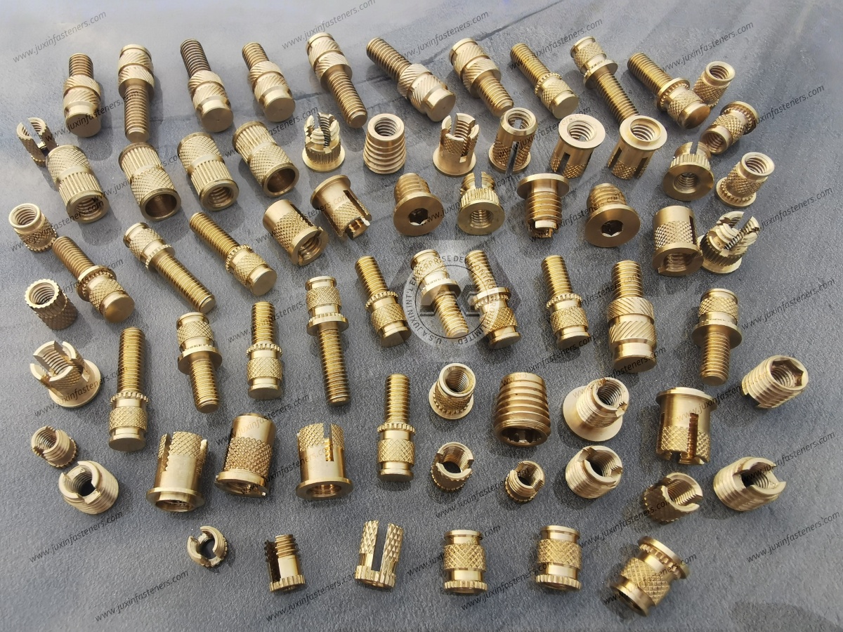
Changing from:
Machined Prototype → Formed Production Component
may alter:
material flow
geometry
surface
dimensional capability
mechanical behavior
Therefore:
Prototype Process ≠ Production Process Qualification.
The production route should be reviewed and validated where required.
The original article claimed effectively perfect concentricity through advanced machining.
A professional aerospace drawing should instead define the actual functional tolerance.
Relevant geometric controls should be specified only where needed.
Therefore:
Precision Marketing Claim ≠ Controlled Drawing Requirement.
Use measurable tolerances.
The original article presented 0.01 mm coaxiality as a typical aerospace precision requirement.
There is no reason to impose the same value on every threaded insert.
Tolerance should be determined by:
Assembly function
interface
manufacturing capability
inspection strategy
customer drawing
Unnecessarily tight tolerances increase cost without necessarily improving the joint.
A tolerance should be:
As Tight as Function Requires, Not as Tight as Manufacturing Can Possibly Achieve.
This improves:
Manufacturability
supplier availability
cost
production stability
while protecting the functional requirement.
A suitable quality plan may include controls for:
Material
dimensions
threads
geometry
hardness where applicable
heat treatment where applicable
surface treatment
visual condition
functional characteristics
packaging
traceability
The exact inspection plan should follow the drawing and customer requirements.
Depending on the project, material control may include:
Material certificates
supplier documentation
composition verification
lot traceability
But:
Raw Material Certificate ≠ Finished Component Performance.
The finished insert must still meet its own drawing and functional requirements.
Thread inspection may include appropriate:
GO / NO-GO gauging
dimensional measurement
customer-specified inspection
depending on thread and drawing requirements.
Thread acceptance alone does not prove installed performance.
An insert can meet every dimensional requirement and still fail if:
Parent material is incompatible
installation is incorrect
coating changes friction
joint load is different
environment is more severe
Therefore:
Drawing Compliance ≠ Installed Joint Validation.
Depending on the application, functional testing may include:
Pull-out
torque-out
proof or load testing
mating-fastener assembly
installation verification
environmental testing
vibration or fatigue testing
when required by the customer or application.
Tests should be selected according to the actual failure mechanism.
A large test package does not automatically produce a safer design.
The correct approach is:
Identify Failure Mode → Define Requirement → Select Representative Test → Establish Acceptance Criteria
Traceability requirements vary by program.
For some applications, procurement may require control of:
Material lot
manufacturing lot
heat-treatment lot
coating lot
inspection record
revision
shipment documentation
The required level should be defined in the purchase and quality requirements.
A component can be fully traceable and still be technically unsuitable.
Traceability tells the customer where the component came from.
Qualification determines whether it is acceptable for the application.
Both can matter, but they serve different purposes.
Supplier-development teams should evaluate:
Drawing control
revision control
material control
manufacturing process
special-process control where applicable
thread inspection
dimensional capability
surface-treatment control
functional testing
documentation
traceability
change management
packaging
production capacity
The required depth should match application risk.
A supplier may be capable of manufacturing:
Titanium components
stainless inserts
aluminum inserts
precision CNC parts
but that does not automatically approve every produced part for an aerospace program.
Therefore:
Manufacturing Capability ≠ Program Qualification.
Aerospace procurement teams may develop second sources for:
Supply continuity
capacity
lead time
geographic risk
cost control
But threaded inserts should not be second-sourced by nominal dimensions alone.
Two inserts can share:
Thread
OD
length
while differing in:
Material
retention geometry
surface treatment
thread friction
heat treatment
installation behavior
parent-material interaction
Therefore:
Same Dimensions ≠ Functional Equivalence.
Compare:
Drawing + Revision + Material + Heat Treatment + Thread + Geometry + Surface Treatment + Installation + Functional Performance + Documentation + Traceability
For critical applications, assembly-level validation may also be required.
Changing from one coating or surface condition to another can affect:
Corrosion
friction
preload
thread fit
electrical behavior
galvanic interaction
Therefore:
Coating Substitution Can Be an Engineering Change.
It should not be made solely by purchasing because the replacement appears visually similar.
Changing from:
Stainless to titanium
steel to stainless
aluminum to titanium
one alloy grade to another
can change:
Strength
stiffness
weight
thermal expansion
corrosion
galvanic behavior
friction
manufacturing
Therefore:
Material Substitution Requires Engineering Review Where Functionally Relevant.
Aerospace procurement should compare more than insert piece price.
A useful framework is:
Total Installed Cost = Part Price + Installation + Tooling + Inspection + Documentation + Rework + Scrap + Maintenance + Logistics + Supply Risk
For some aerospace programs, additional costs may include:
Qualification
special inspection
traceability
controlled packaging
customer approval
A lower piece price may not create a lower total cost.
A standard insert can be attractive when:
Geometry fits
material is acceptable
installation is proven
required documentation is available
Custom inserts may be justified when the application requires:
Special thread
Restricted envelope
Low mass
Custom retention geometry
Special material
Special surface treatment
Controlled installation interface
Drawing-specific features
Customization should solve a real engineering problem.
Unnecessary custom geometry can increase:
Tooling
cost
lead time
supplier dependence
qualification complexity
Use standard components where they satisfy the requirement.
Use custom components where function justifies them.
For a custom aerospace threaded insert, DFM should consider:
Material availability
Thread
diameter
length
wall thickness
undercuts
knurls
grooves
tolerances
surface treatment
inspection access
production volume
The objective is not simply to manufacture the drawing.
The objective is to create a drawing that can be manufactured consistently while preserving the required function.
Extremely tight tolerances or difficult-to-measure features can increase:
Manufacturing cost
inspection time
equipment requirements
supplier risk
Therefore design engineers should distinguish between:
Function-Critical Characteristics
and:
Non-Critical Dimensions.
For a useful technical and commercial quotation, provide:
2D drawing
3D model where available
Part number
Drawing revision
Application
Application classification
Parent material
Parent-material specification
Parent-material thickness
Hole / installation geometry
Internal thread
Mating fastener
Insert material
Heat treatment where applicable
Surface treatment
Installation method
Required pull-out / torque-out performance where applicable
Required load
Tightening requirement
Operating temperature
Vibration environment where relevant
Corrosion environment
Chemical exposure
Galvanic considerations
Annual volume
Prototype quantity
Inspection requirement
Traceability requirement
Documentation requirement
Applicable ISO, DIN, EN, ASTM, SAE, ASME/ANSI or customer / aerospace program specification
Provide:
Aluminum alloy
temper
thickness
edge distance
hole geometry
surface treatment
mating fastener material
corrosion environment
This helps evaluate both mechanical and galvanic compatibility.
Provide:
Composite system
laminate / structural information relevant to the joint
thickness
hole preparation
edge distance
insert installation method
load direction
environmental requirement
galvanic-isolation requirement
Do not treat a composite component as an aluminum component with lower weight.
Provide:
Polymer family
Exact grade where known
Reinforcement
boss geometry
pilot hole
installation method
temperature
moisture
chemical exposure
pull-out / torque-out requirement
Provide:
Original thread
damaged condition
parent material
repair location
applicable approved repair documentation
required replacement thread
installation limitation
JUXIN FASTENERS can manufacture to an approved drawing or requirement where technically appropriate,
but approval of an aviation repair remains the responsibility of the applicable authorized engineering and maintenance process.
A controlled process can follow:
Application → Parent Material → Load → Thread → Insert Geometry → Material → Surface Treatment → Installation
→ Prototype → Inspection → Functional Validation → Customer Approval → Production
For a custom component:
Drawing → DFM Review → Material → Manufacturing Route → Sample → Dimensional Inspection → Assembly Trial → Functional Validation → Approval → Production
For a second source:
Approved Drawing → Revision → Material → Process → Surface Treatment → Sample → Comparison → Functional Validation → Documentation Review → Approval
Before specifying an aerospace threaded insert, answer the following questions.
Is it:
Ground-support equipment?
Avionics enclosure?
Interior equipment?
Maintenance tooling?
Secondary equipment?
Flight-critical structure?
This determines the required qualification level.
Identify the actual:
Alloy
temper
polymer
composite system
not merely “aluminum,” “plastic” or “carbon fiber.”
Is the objective:
Reusable thread?
Stronger thread interface?
Repair?
Serviceability?
Replaceability?
Thin-material thread creation?
The insert type should follow the actual requirement.
Determine whether the insert must resist:
Axial load
Shear
Rotation
Combined loading
cyclic loading
Do not specify only a generic “high-strength insert.”
Determine whether the critical failure is:
Screw failure
Thread stripping
Insert pull-out
Insert rotation
Parent-material failure
fatigue
Define:
Temperature
humidity
corrosion
chemicals
vacuum where applicable
vibration
Evaluate:
Insert
mating screw
parent material
coating
for galvanic and tribological compatibility.
If yes, evaluate:
Thread wear
galling
replacement strategy
access
service torque
Define this before quotation.
Possible requirements can include:
Material certification
inspection records
traceability
coating documentation
customer-specific quality records
Select testing according to the application and customer specification rather than using a generic “aerospace test package.”
This page should function as the dedicated Aerospace Threaded Inserts / Precision Insert Engineering & Sourcing resource.
Recommended internal links include:
Threaded Inserts for Plastic → polymer boss design, heat-set and ultrasonic insert engineering
Aluminum Fasteners → aluminum fastener material and threaded-joint engineering
Fasteners for Aluminum → threaded attachment technologies for aluminum components
Stainless Steel Fasteners → stainless material, corrosion and galling
Lightweight Automotive Fasteners → cross-material lightweight fastening principles
Fastener Surface Treatment & Coating Selection → corrosion, friction and coating engineering
Zinc-Nickel Coated Fasteners → coating selection where technically applicable
Custom Fastener Manufacturing → CNC, forming, DFM and drawing-based manufacturing
Industrial Fastener Solutions → fastening technology selection
Fastener Quality Control Resources → supplier qualification, inspection and second-source control
Use the existing indexed JUXIN FASTENERS URL when implementing these internal links.
Threaded inserts can provide reusable or reinforced threads in suitable aluminum, composite, polymer and other lightweight structures used in electronic equipment,
instrument housings, access components, ground-support equipment and other drawing-controlled assemblies.
No. Suitability depends on the specific application, parent material, load, environment and program requirements.
Flight-critical and safety-critical applications require approved specifications and qualification.
There is no universal best material. Aluminum, steel, stainless steel, titanium and other materials have different advantages and tradeoffs.
No. Titanium can provide excellent specific strength and corrosion characteristics, but cost, galling, galvanic compatibility,
manufacturing and the actual joint requirement must be considered.
Potentially, but mechanical and galvanic compatibility should be evaluated for the actual environment.
No. Material selection should follow corrosion environment, mechanical requirements and customer specifications.
They can be suitable for selected non-critical equipment, instruments, electronics or polymer assemblies where the material meets the engineering requirements.
They should not automatically be described as structural aerospace-grade hardware.
Pull-out relates to axial extraction from the parent material. Torque-out relates to rotation of the insert within the parent material.
No. Insert torque-out and screw self-loosening are different failure mechanisms.
Not automatically. Threaded inserts provide a threaded interface. Vibration resistance depends on the complete joint design, preload, friction, locking strategy and dynamic loading.
Not necessarily. The parent material or insert-retention interface may control the joint.
No. Excessive tightening can overload the insert, parent material or mating fastener.
No. Knurling can contribute to retention or grip depending on the design, but it does not automatically prevent mating-screw self-loosening.
No. Corrosion depends on material, coating, mating materials, environment and joint geometry.
No. Salt-spray hours are not equivalent to real field service life.
Not automatically. Manufacturing route should be selected according to material, geometry, tolerance, volume and functional requirements.
No. The required geometric tolerance should be established by the functional drawing. Unnecessarily tight tolerances can increase cost without improving performance.
Only if it meets the applicable design, material, quality, documentation and approval requirements for that specific application.
Flight-critical or safety-critical components require customer/OEM-approved drawings, specifications, qualification and quality requirements.
Manufacturing capability alone should never be interpreted as automatic aerospace program approval.
Threaded inserts can be part of approved repair methods, but the repair must follow the applicable OEM, maintenance or authorized engineering documentation.
Physical fit alone does not constitute repair approval.
Send the controlled drawing, revision, application, parent material, mating fastener, load requirements, material, surface treatment, installation method, environment,
inspection requirements, documentation requirements, annual volume and applicable customer or program specifications.
Compare drawing revision, material, thread, geometry, manufacturing process, surface treatment, installation behavior, functional performance, documentation and traceability as required.
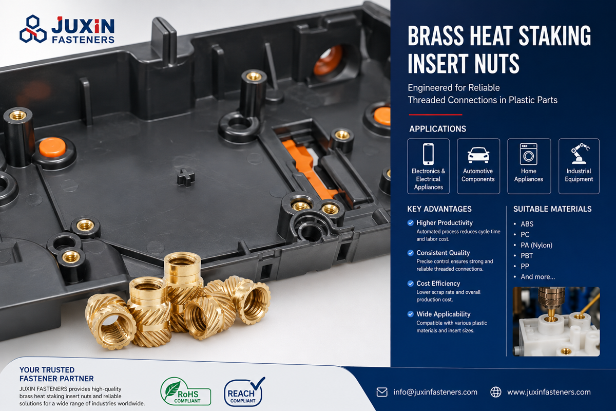
The most important lesson for aerospace threaded-insert engineering is that the insert is only one element of the load path.
The correct engineering sequence is:
Application → Parent Material → Load Path → Insert Type → Material → Thread → Installation → Mating Fastener → Environment → Validation → Supplier Qualification
The key principles are:
Strong Insert ≠ Strong Installed Joint
Insert Strength ≠ Assembly Strength
Same Insert + Different Parent Material ≠ Same Joint Performance
Stronger Screw ≠ Stronger Parent Material
Lightweight Insert ≠ Lightweight Joint
Titanium ≠ Automatic Aerospace Upgrade
Stainless Steel ≠ Corrosion-Proof
Material Grade ≠ Finished Component Compliance
Correct Thread ≠ Correct Insert
Strong Internal Thread ≠ Strong Installed Insert Joint
Torque ≠ Preload
Same Torque + Different Friction ≠ Same Preload
Dry Torque ≠ Lubricated Torque
Knurl ≠ Automatic Vibration Lock
Insert Torque-Out ≠ Screw Anti-Loosening Performance
Threaded Insert ≠ Anti-Loosening Device
Locking Feature ≠ Correct Tightening
High Strength ≠ High Fatigue Life
Room-Temperature Fit ≠ Full-Temperature Joint Validation
Aerospace Fastener ≠ Space-Qualified Fastener
Mechanical Fastening ≠ Electrical Safety
Conductive Material ≠ Qualified Electrical Connection
Composite ≠ Lightweight Metal
Corrosion-Resistant Insert ≠ Corrosion-Resistant Assembly
Salt Spray Hours ≠ Aerospace Service Life
Component Quality ≠ Installed Joint Quality
Drawing Compliance ≠ Installed Joint Validation
Raw Material Certificate ≠ Finished Component Performance
Traceability ≠ Qualification
Manufacturing Capability ≠ Program Qualification
Same Dimensions ≠ Functional Equivalence
Coating Substitution Can Be an Engineering Change
Material Substitution Can Be an Engineering Change
For design engineers, the objective is to define a reliable load path between the mating fastener, insert and parent structure.
For procurement and supplier-development teams, the objective is to source a component that remains technically controlled when material,
manufacturing process, surface treatment, supplier or production volume changes.
JUXIN FASTENERS supports selected drawing-based projects involving:
Threaded inserts
Stainless steel inserts
Alloy steel inserts
Titanium fastening components
Aluminum fastening components
Brass inserts
Inserts for engineering plastics
Precision CNC components
Custom screws
Custom nuts
Custom bolts
Standoffs and spacers
Drawing-based OEM fasteners
For an effective RFQ, provide:
2D Drawing + 3D Model + Part / Revision + Application + Parent Material + Thread + Mating Fastener + Load Requirement + Insert Material
+ Surface Treatment + Installation Method + Temperature + Corrosion Environment + Inspection Requirement + Documentation / Traceability Requirement + Annual Volume
For aerospace applications, also identify whether the component is intended for:
Ground Support / Equipment / Interior / Avionics / Secondary Attachment / Flight-Critical or Safety-Critical Application
and provide the applicable customer, OEM or program specification where required.
This allows the fastener to be evaluated as part of the actual assembly rather than as an isolated metal component.
JUXIN FASTENERS
Aerospace Threaded Inserts | Precision Inserts | Custom Fasteners | Drawing-Based OEM Components
Email: info@juxinfasteners.com
Website: www.juxinfasteners.com
Contact Us
Tel.:
+86 020 8621 0320
+86 020 3121 6067
E-mail:
Technical Support:
Navigation
SEND INQUIREY



