
Call Us
+86 136 6007 9809
Call Us
+86 136 6007 9809

Sep. 30, 2026
Bearings, gears, pulleys, rollers, spacers, seals, and other machine components frequently need to be located and retained axially on shafts or inside housing bores.
One solution is to machine a shoulder or use a threaded nut, collar, or other separate retention system.
Another is to use an axial retaining ring installed into a machined groove.
External retaining rings fit into grooves on shafts. Internal retaining rings fit into grooves inside bores or housings.
Once installed, the ring creates a compact axial shoulder that restricts movement of the retained component.
The concept appears simple.
But the ring alone does not determine the performance of the assembly.
A reliable retaining-ring joint depends on the interaction between:
Ring + Groove + Shaft or Housing + Retained Component + Load + Installation + Operating Conditions
For design engineers, this leads to an important question:
Will the ring fail first, or will the groove, shaft, housing, or mating component become the limiting element?
For procurement and supplier-development teams, the corresponding question is:
Which dimensions, materials, heat-treatment conditions, finishes, and functional characteristics must remain equivalent when an axial retaining ring is second-sourced?
JUXIN FASTENERS supplies standard and drawing-based external retaining rings, internal retaining rings, circlips, shaft rings, housing rings,
and related stamped retention hardware for industrial equipment and OEM sourcing programs.
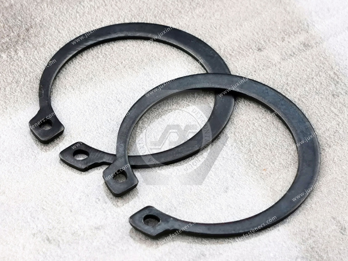
An axial retaining ring is a spring-type mechanical retention component installed into a circumferential groove.
Depending on the design, installation requires the ring to temporarily expand or contract.
After installation, the ring returns toward its free condition and remains engaged with the groove.
When the retained component moves axially, it contacts the ring.
The ring then transfers load into the groove and surrounding shaft or housing material.
This creates a load path:
Retained Component → Retaining Ring → Groove → Shaft or Housing
Understanding this load path is more useful than considering the retaining ring as an isolated fastener.
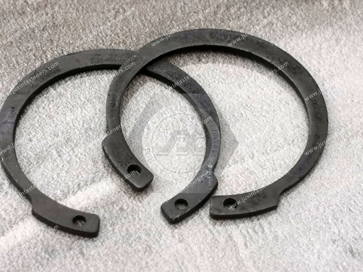
External retaining rings are installed into grooves around the outside diameter of a shaft.
Typical retained components can include:
bearings;
gears;
pulleys;
rollers;
spacers;
levers;
rotating machine components.
During installation, the ring is expanded enough to pass over the shaft and reach the groove.
Once positioned, it contracts toward the groove.
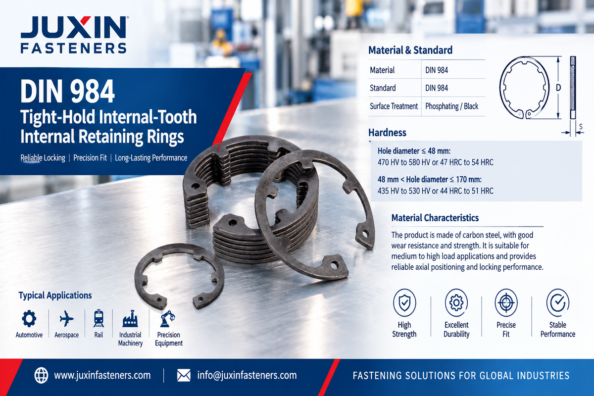
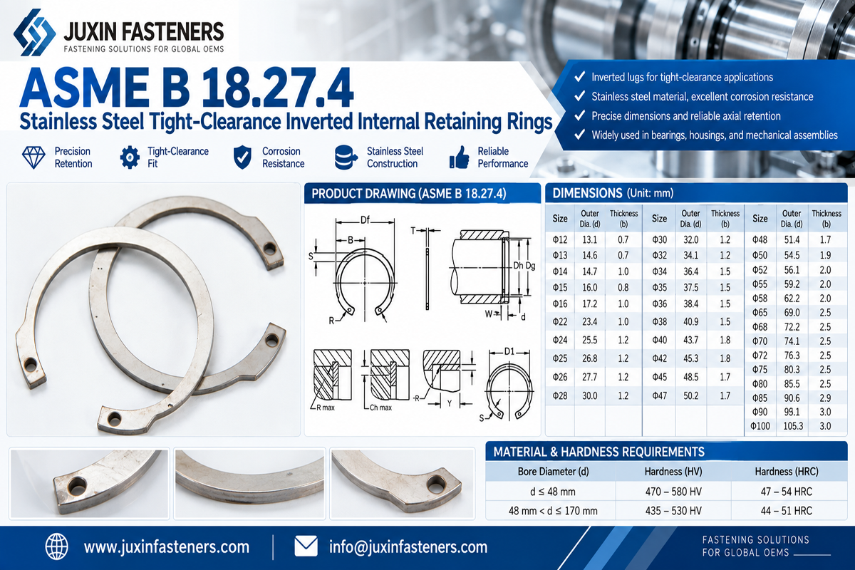
Internal retaining rings are installed into grooves machined inside a bore or housing.
Typical applications include retention of:
bearings;
bushings;
seals;
sleeves;
internal spacers;
other cylindrical components.
During installation, the ring is compressed to enter the bore and then allowed to expand into the groove.
External and internal rings may appear conceptually similar, but their geometry and installation behavior are different.
They should not be treated as interchangeable versions of the same component.
A common sourcing mistake is to focus entirely on the retaining ring.
In reality, the groove can be equally important.
Critical groove characteristics may include:
groove diameter;
groove width;
groove depth;
groove location;
sidewall geometry;
corner radius;
surface condition;
shaft or housing material.
If the groove does not properly support the ring, selecting a stronger ring may not solve the retention problem.
This is why retaining-ring engineering should begin with the complete interface.
Consider a bearing retained on a shaft by an external retaining ring.
When an axial force moves the bearing toward the ring:
The bearing contacts the retaining ring.
The ring receives the axial load.
The ring bears against the groove wall.
The groove transfers the load into the shaft.
The capacity of the assembly may therefore depend on several different potential limits:
deformation of the ring;
ring disengagement;
groove deformation;
groove material shear or yielding;
deformation of the retained component;
excessive axial movement.
The lowest-capacity element can govern the complete assembly.
Therefore:
Retaining-ring capacity is not automatically equal to retaining-system capacity.
Suppose a hardened spring-steel ring is installed on a relatively softer shaft.
The ring itself may be capable of carrying substantial load, but the shaft material surrounding the groove may deform first.
Similarly, an internal retaining ring installed in a softer housing can transfer concentrated load into the groove wall.
For this reason, engineers should evaluate:
shaft or housing material;
material strength;
groove geometry;
ring geometry;
axial load;
safety requirements.
Simply increasing ring thickness does not guarantee a proportional increase in assembly capacity if the groove becomes the limiting element.
The groove must provide sufficient engagement with the retaining ring while maintaining adequate remaining shaft or housing section.
For an external ring, machining a deeper groove can increase geometric engagement but also reduces the remaining shaft diameter at the groove.
For an internal ring, groove geometry similarly affects the remaining housing section.
This creates a design trade-off:
Ring Engagement ↔ Remaining Parent-Material Section
The groove should therefore follow the dimensional requirements of the selected retaining-ring system rather than being designed independently.
Groove width affects how the ring seats and how much axial movement may occur.
If the groove is excessively wide relative to the ring thickness, additional axial movement may occur before the ring bears against the loaded groove wall.
If the groove is too narrow, installation and proper seating may be affected.
The relationship between:
ring thickness;
groove width;
retained-component position;
required end play
should be considered together.
A retaining ring requires appropriate groove geometry to transfer axial load effectively.
However, specifying an infinitely sharp groove corner is neither realistic nor necessarily desirable.
Machining always produces some radius, and excessively sharp transitions can increase local stress concentration in the shaft or housing.
At the same time, an excessive radius can interfere with proper ring seating or reduce effective load-bearing geometry.
The correct groove radius should therefore follow the applicable ring design, drawing, standard, and engineering requirements.
The objective is:
Proper ring seating + adequate load-bearing geometry + acceptable stress concentration
—not simply the sharpest possible corner.
The groove is not the only radius that matters.
A bearing, washer, gear, pulley, or spacer positioned against the ring may also have:
chamfers;
corner radii;
relieved edges.
These features influence how the retained component contacts the ring.
If the component geometry does not provide appropriate contact, load may be applied unfavorably to the ring.
For precision applications, engineers should evaluate the complete axial interface rather than only the groove drawing.
Retaining rings are commonly used to resist axial loads.
However, “axial load” should not be treated as one universal condition.
Applications can involve:
constant axial load;
intermittent thrust;
reversing axial load;
shock;
vibration;
cyclic loading.
A gearbox bearing and a low-load enclosure component may use visually similar retention concepts while experiencing very different service conditions.
The load case should therefore be defined before selecting the ring.
A static load rating does not describe every operating condition.
Impact or cyclic axial loading can introduce:
repeated ring-to-groove contact;
local deformation;
wear;
changing end play;
fatigue-related effects.
Where significant dynamic loading exists, engineers should evaluate the retaining system under the actual duty cycle rather than relying only on nominal static load.
External retaining rings installed on rotating shafts experience centrifugal effects.
As rotational speed increases, the mass of the ring experiences outward radial force.
Depending on ring geometry, shaft diameter, material, free diameter, and speed, this can influence groove engagement.
This does not mean that every external retaining ring has a simple universal RPM limit.
High-speed suitability should be evaluated according to the specific ring design and application.
Relevant factors include:
shaft diameter;
ring geometry;
ring mass;
rotational speed;
groove geometry;
material;
balance requirements;
operating environment.
For high-speed motor, spindle, transmission, or rotating-equipment applications, rotational conditions should be included in the engineering review and RFQ.
Two applications operating at the same RPM may not create the same retaining-ring condition.
A larger shaft produces different circumferential velocity and centrifugal effects than a much smaller shaft at the same rotational speed.
Therefore, simply asking:
“What is the maximum RPM?”
without identifying ring size and shaft geometry can be misleading.
High-speed evaluation should consider the complete rotating system.
Retaining rings rely on elastic behavior during installation.
An external ring must be expanded.
An internal ring must be compressed.
But the ring should only be deformed as much as required for installation.
Excessive expansion or compression can create permanent set.
If permanent deformation occurs, the ring may no longer return sufficiently toward its intended installed geometry.
Possible consequences include:
reduced groove engagement;
poor seating;
increased risk of disengagement;
inconsistent assembly.
Installation tooling is therefore part of retaining-ring performance.
Circlip pliers or dedicated automated tooling should match the ring configuration and production method.
The objective is to:
control expansion or compression;
maintain alignment;
avoid twisting;
prevent excessive deformation;
seat the ring completely in the groove.
High-volume production may also require automated or semi-automated installation and inspection.
A ring that is correctly manufactured but incorrectly installed can still produce an unreliable assembly.
After installation, the ring should be properly seated in its intended groove.
Potential installation problems include:
partial seating;
twisted ring;
one end outside the groove;
contamination in the groove;
excessive permanent deformation;
incorrect ring orientation where orientation is relevant.
Visual inspection, dimensional checks, automated sensing, or functional inspection may be appropriate depending on the application and production volume.
Some assemblies require controlled axial clearance rather than absolute zero movement.
Potential reasons include:
thermal expansion;
bearing requirements;
manufacturing tolerances;
lubrication;
assembly capability.
Trying to eliminate all end play with a conventional retaining ring can create unintended preload or tolerance problems.
Where axial clearance must be reduced or controlled, designers may consider appropriate ring configurations, shims, washers, spring elements, or other retention architectures.
The correct solution depends on the assembly.
Bowed or curved retaining rings can provide spring action in the axial direction.
They may be useful where an assembly requires take-up of limited axial clearance.
However, a bowed ring should not automatically be substituted for a flat retaining ring.
The design changes:
axial force behavior;
installed geometry;
available travel;
retained-component position.
The complete stack-up should be reviewed before substitution.
Both can provide axial retention, but they create different design architectures.
Potential advantages include:
compact radial and axial packaging;
low component count;
no threaded clamping screw in many configurations.
However, they normally require a groove.
Can often be installed without machining a retaining-ring groove but occupy more axial and radial space.
Selection depends on:
load;
shaft geometry;
available space;
machining;
assembly sequence;
adjustability;
service requirements.
A threaded shaft end and retaining nut can provide robust axial retention and adjustment in suitable designs.
But this requires:
shaft threading;
axial space;
nut installation;
potentially additional locking hardware.
A retaining ring can reduce packaging space and machining complexity in suitable applications.
The choice should be based on engineering requirements rather than assuming one architecture is universally better.
A machined shoulder can provide a strong integral locating surface.
However, a shoulder alone only retains the component from one direction.
The opposite side may still require another retention feature.
Retaining rings are often used together with shoulders:
Machined Shoulder → Component → Retaining Ring
This architecture can provide compact axial location without requiring a threaded end.
Retaining rings can be manufactured from different materials depending on the application.
Potential material families include:
carbon spring steels;
stainless steels;
other spring-capable alloys where specified.
Material selection can depend on:
required spring behavior;
strength;
corrosion environment;
temperature;
customer specification;
applicable standard.
Do not assume that all retaining rings use the same spring-steel grade or heat-treatment condition.
For second-source projects, the approved material specification should be reviewed.
Depending on material and environment, retaining rings may use surface treatments or finishes for corrosion protection or other functional requirements.
Selection should consider:
indoor vs. outdoor use;
humidity;
salt exposure;
industrial chemicals;
mating materials;
temperature;
customer corrosion requirements.
If corrosion testing is required, the applicable test method, duration, acceptance criteria, substrate, and finish should be specified rather than simply requesting a generic “salt spray” result.
| Engineering Requirement | Typical Retaining Solution | Critical Interface |
|---|---|---|
| Bearing retained on shaft | External retaining ring | Shaft groove + bearing contact |
| Gear or pulley retained on shaft | External shaft ring | Groove + axial load |
| Bearing retained inside housing | Internal retaining ring | Housing groove + bearing outer race |
| Bushing retained in bore | Internal circlip | Bore groove + bushing geometry |
| Controlled axial take-up | Bowed/spring-type ring where suitable | Stack-up + spring deflection |
| High-speed rotating shaft | Application-specific external ring evaluation | Ring + groove + shaft + rotational speed |
The matrix is a starting point. Final selection should follow the specific load and interface requirements.
The ring and groove are one retention system.
The shaft or housing groove may become the limiting feature.
Poor contact geometry can alter how axial load reaches the ring.
This can create permanent deformation.
The same problem can occur with internal rings.
Ring size and rotating geometry also matter.
This can create unintended preload or assembly problems.
Nominal shaft size alone does not define functional equivalence.
For procurement and supplier-development teams, a retaining ring should not be second-sourced solely from appearance.
A useful principle is:
Visual Similarity ≠ Dimensional Equivalence ≠ Groove Equivalence ≠ Spring Equivalence ≠ Functional Equivalence
Identify:
external or internal;
standard or special configuration;
flat or bowed;
installation features;
orientation where applicable.
Depending on the ring, relevant dimensions may include:
ring thickness;
radial width;
free diameter;
lug geometry;
hole dimensions;
opening geometry;
installed diameter;
applicable groove dimensions.
Where specified, verify:
material;
heat treatment;
hardness;
spring characteristics;
surface finish.
A second-source review should consider:
shaft or bore diameter;
groove diameter;
groove width;
groove location;
corner geometry;
parent material.
Where required, evaluation may include:
dimensional inspection;
installation trials;
groove fit;
axial retention;
permanent-set assessment;
corrosion testing;
high-speed evaluation for rotating applications.
The validation plan should match the actual application.
A sample can help identify:
ring style;
nominal dimensions;
thickness;
free diameter;
lug geometry;
finish.
But a sample may not reveal:
original material specification;
heat-treatment requirement;
hardness range;
dimensional tolerances;
required axial load;
maximum installation deformation;
intended groove specification;
operating RPM;
corrosion requirement.
Whenever possible, the sample should be accompanied by the drawing and application information.
Before approving a second source for axial retaining rings or circlips, consider defining:
approved drawing revision;
retaining-ring type;
applicable international standard where required;
nominal shaft or bore size;
ring dimensions;
groove dimensions;
material;
heat treatment or hardness where specified;
finish or coating;
shaft or housing material;
axial load requirement;
dynamic or shock loading where relevant;
rotational speed for rotating shaft applications;
operating temperature;
corrosion requirements;
installation method;
inspection requirements;
sample-validation requirements;
packaging;
production quantity;
estimated annual usage.
For technical review and quotation, provide as much of the following information as applicable:
2D drawing;
3D CAD model where available;
existing or competitor reference part number;
physical sample for cross-reference;
external or internal ring type;
shaft diameter or bore diameter;
groove diameter;
groove width;
groove location;
retained-component geometry;
required axial load;
rotational speed where applicable;
shaft or housing material;
ring material requirement;
hardness or heat-treatment requirement where specified;
finish or coating;
operating temperature;
corrosion environment;
installation method;
applicable ISO, DIN, ASME/ANSI, BS, EN, SAE or ASTM requirements where relevant;
inspection/documentation requirements;
sample quantity;
production quantity;
estimated annual usage.
JUXIN FASTENERS can use this information to evaluate retaining-ring configuration, dimensional requirements, groove compatibility,
drawing or sample cross-reference feasibility, validation requirements, and the appropriate production sourcing route.
For engineering teams, a useful selection path is:
Retained Component → Shaft/Bore → Axial Load → Groove → Ring Type → Material → Rotation/Environment → Installation → Validation
For procurement teams, the sourcing path continues:
Drawing / Existing Ring → Critical Characteristic Review → Groove Compatibility → Material & Dimensional Cross-Reference
→ Sample Installation → Functional Validation → Second-Source Approval → Production RFQ
The key principle is simple:
Do not design or source the retaining ring separately from its groove.
A reliable axial retention system depends on the interaction between the ring, groove, shaft or housing material, retained component, installation process, and actual service load.
Email: info@juxinfasteners.com
Website: www.juxinfasteners.com
 MORE NEWS
Sep. 30, 2026
Sep. 30, 2026
Sep. 30, 2026
Contact Us
Tel.:
+86 020 8621 0320
+86 020 3121 6067
E-mail:
Technical Support:
Navigation
SEND INQUIREY