
Call Us
+86 136 6007 9809
Call Us
+86 136 6007 9809

Sep. 30, 2026
Plastic housings are widely used in electronics, automotive components, industrial automation, appliances, power tools,
telecommunications equipment, lighting systems, and other engineered products because they reduce weight, provide electrical insulation,
support complex molded geometries, and simplify high-volume manufacturing.
But creating a reliable threaded joint in thermoplastic requires more than selecting a screw.
Directly formed or thread-forming screw joints can be appropriate for many plastic assemblies, particularly where the number of assembly
cycles and joint loads are limited. However, applications requiring repeated service, reusable machine threads, higher local loads, or controlled metal-to-metal threaded engagement may benefit from a metal threaded insert.
Threaded inserts for plastic create a metal female thread inside the polymer component while transferring installation and service loads into the surrounding plastic.
The critical engineering question is not simply:
“Which brass insert fits my screw?”
It is:
“Which insert geometry, installation method, boss design, and polymer interface will produce the required joint performance?”
For procurement and supplier-development teams, the question becomes:
“Which characteristics must remain equivalent when an existing plastic insert is cross-referenced or second-sourced?”
JUXIN FASTENERS supplies standard and drawing-based brass threaded inserts, heat-set inserts, ultrasonic inserts, molded-in inserts,
expansion-style inserts, and related fastening components for plastic assemblies.
A plastic boss and a metal threaded insert perform different functions.
The insert provides the reusable internal thread.
The surrounding polymer retains the insert and transfers loads into the molded component.
This distinction is important because a strong metal thread does not automatically create a strong plastic joint.
The performance of the complete assembly depends on:
polymer type and grade;
glass or mineral reinforcement;
insert geometry;
insert outside diameter;
insert length;
boss dimensions;
hole geometry;
installation process;
screw engagement;
tightening torque;
operating temperature;
environmental exposure.
The insert and molded plastic must therefore be engineered as one system.
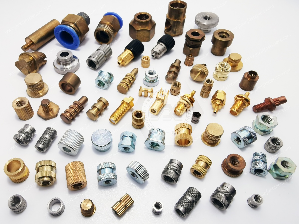
Metal inserts are not required for every plastic assembly.
Direct screw fastening into plastic may be appropriate where the joint is assembled only a limited number of times and the required load can be supported by the polymer.
A threaded insert becomes particularly useful when the application requires:
repeated assembly and disassembly;
reusable machine threads;
higher resistance to thread wear;
controlled screw engagement;
serviceable covers or modules;
increased local load capability;
metal-thread compatibility with standard machine screws.
The correct choice should be based on the application's actual service requirements rather than assuming either method is universally superior.
Threaded inserts can be installed using several fundamentally different methods.
Understanding these methods is important because the same boss design should not automatically be used for every insert family.
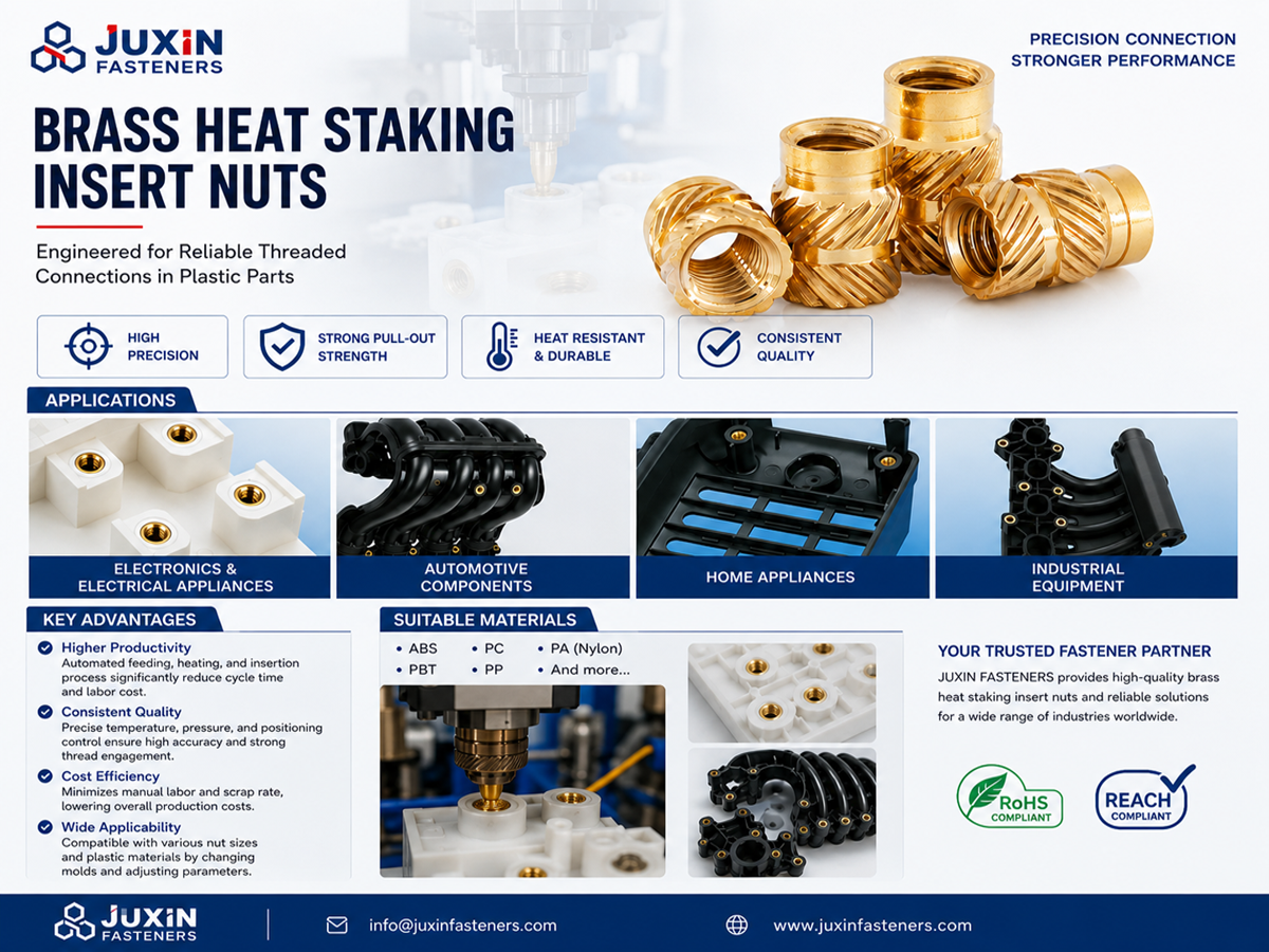
Heat-set inserts are installed after molding.
A controlled heated installation tool transfers thermal energy into the insert. The surrounding thermoplastic softens locally as the insert enters the prepared boss.
Plastic then flows around external retention features such as knurls, grooves, or undercuts.
After the material cools, the polymer solidifies around the insert.
Heat-set inserts are commonly considered for thermoplastic materials because the polymer can soften during installation and resolidify around the insert geometry.
Heat-set performance can depend on:
insert temperature;
installation speed;
axial alignment;
insertion depth;
boss-hole geometry;
polymer type;
insert geometry;
cooling condition.
Higher temperature is not automatically better.
Excessive heat can produce unwanted melting, boss deformation, polymer degradation, or poor dimensional control.
Insufficient heat can require excessive insertion force and may damage the boss.
The objective is controlled local softening and material flow.
Ultrasonic insertion also installs the insert after molding, but heat is generated locally through high-frequency mechanical vibration at the insert-to-polymer interface.
As the material softens, controlled axial force advances the insert into the boss.
Potential advantages in suitable high-volume production include rapid installation and integration into automated assembly processes.
However, process performance depends on the combination of:
insert geometry;
polymer;
ultrasonic equipment;
amplitude;
pressure;
insertion depth;
boss design.
A component called an “ultrasonic insert” should therefore be evaluated together with the intended installation process rather than only by its external dimensions.
Molded-in inserts are positioned in the mold before polymer injection.
The plastic forms around the insert during the molding cycle.
This eliminates a separate post-mold insertion operation but creates a different manufacturing architecture.
Engineering considerations include:
insert positioning;
mold retention;
insert movement during injection;
plastic flow around the insert;
contamination of internal threads;
molding cycle handling;
automation;
mold protection.
Molded-in inserts can be effective in suitable programs, but they should not automatically be considered superior to post-mold insertion.
The decision depends on production volume, mold architecture, cycle time, automation strategy, component geometry, and required joint performance.
Some inserts use mechanical interference or expansion rather than thermal or ultrasonic insertion.
Depending on the design, the insert may be pressed into a prepared hole or mechanically expanded after positioning.
These products have different boss and installation requirements from heat-set inserts.
A press-in insert should not automatically be substituted for a thermal insert simply because the internal thread and overall dimensions appear similar.
The external surface of a threaded insert transfers load into the surrounding polymer.
Different insert designs may use:
straight knurls;
diagonal knurls;
opposing knurl directions;
grooves;
undercuts;
barbs;
expansion features;
combinations of retention geometries.
These features influence how the surrounding polymer resists axial and rotational movement.
However, there is no universal rule that one knurl pattern is always strongest.
Performance depends on the complete combination of:
Insert Geometry + Polymer + Boss + Installation Process + Load Direction
This is particularly important when second-sourcing an existing insert.
Two inserts can have the same internal thread and similar outside diameter while using significantly different external retention geometry.
Threaded insert performance is often discussed using two different load concepts.
Pull-out loading attempts to extract the insert axially from the plastic.
Performance can be influenced by:
insert length;
insert diameter;
retention geometry;
polymer properties;
boss dimensions;
installation quality;
temperature;
distance from nearby free edges.
Torque-out loading attempts to rotate the insert inside the boss.
It becomes particularly important during screw tightening and removal.
The external insert geometry must transfer this rotational load into the surrounding polymer.
A design that performs well under axial pull-out is not automatically optimized for rotational resistance.
Therefore, procurement specifications should avoid asking only for generic “insert strength.”
The required failure mode and test condition should be identified.
One of the most important design principles for threaded inserts is:
The insert cannot be engineered independently from the boss.
The boss must provide enough polymer around the insert to accept installation stresses and service loads without splitting, excessive deformation, or creep.
Important boss characteristics include:
outside diameter;
wall thickness;
hole diameter;
hole depth;
draft;
bottom geometry;
distance from nearby walls;
ribs or gussets;
molded material condition.
There is no single universal boss-wall-thickness ratio that applies to every insert and polymer.
The appropriate dimensions should be based on the selected insert, material, molding process, and validation requirements.
For post-mold insertion, the receiving hole is a critical interface.
If the hole is too small, installation may displace excessive polymer and generate high radial stress.
Potential consequences include:
boss cracking;
bulging;
excessive insertion force;
insert misalignment;
dimensional distortion.
If the hole is too large, insufficient material may engage the external insert geometry.
Potential consequences include:
reduced pull-out resistance;
reduced torque resistance;
loose installation;
inconsistent seating.
The recommended hole therefore depends on the specific insert and polymer rather than on the internal thread size alone.
A frequently overlooked failure mode occurs when the mating screw bottoms in the blind hole or against the bottom of the insert before the intended components are fully clamped.
If tightening continues, the resulting axial force can be transferred directly into the insert and plastic boss.
This can contribute to:
insert pull-out;
boss cracking;
damaged threads;
misleading torque readings.
Engineers should therefore verify:
Screw Length + Component Stack + Insert Thread Depth + Hole Depth
as one assembly stack.
A joint problem that appears to be “poor insert retention” may actually originate from incorrect screw length.
Plastic housings may use either blind or through-hole insert locations.
Each architecture creates different considerations.
Advantages can include maintaining a closed external surface.
Engineering considerations include:
hole depth;
insert seating depth;
trapped material;
screw bottoming;
available polymer below the insert.
A through-hole may simplify some manufacturing and inspection operations but changes packaging, appearance, sealing, and screw-clearance considerations.
The correct geometry depends on the product architecture.
“Plastic” is not one engineering material.
Thermoplastics can differ substantially in:
stiffness;
toughness;
melting or softening behavior;
creep;
moisture absorption;
thermal expansion;
chemical resistance;
reinforcement.
Common engineering polymers may include ABS, polycarbonate, polyamide, polypropylene, and other thermoplastic systems.
The insert and installation process should be evaluated with the actual resin grade whenever joint performance is important.
Adding glass fiber can increase stiffness and modify dimensional behavior, but it also changes how the polymer responds during insert installation.
A boss designed and validated for an unfilled polymer should not automatically be assumed equivalent when the resin changes to a glass-filled grade.
Potential differences can involve:
material flow during insertion;
boss cracking behavior;
insertion parameters;
retention performance;
wear;
thermal response.
For sourcing and validation, procurement should provide the complete polymer grade and reinforcement percentage when available rather than only stating “PA66” or “PC.”
Thermoplastics are viscoelastic materials.
Under sustained stress, their deformation can change with time, temperature, and load.
This matters in threaded joints because excessive local compression of the plastic can reduce clamp load over time.
A metal insert improves the thread interface but does not eliminate creep from the surrounding plastic structure.
Engineers should therefore consider:
joint stack materials;
bearing area;
screw preload;
service temperature;
duration of loading;
boss geometry.
The objective should be to create the required clamp load without unnecessarily over-compressing the plastic assembly.
Increasing insert length can increase the available interface area, but it also requires a deeper boss and more material.
A longer insert can affect:
housing wall thickness;
molding geometry;
screw length;
packaging space;
installation cycle;
boss stiffness.
The correct insert length should balance load requirements with the available plastic geometry.
Simply selecting the longest insert that fits is not an engineering rule.
Brass is widely used for threaded inserts because it offers useful machinability, corrosion characteristics, and compatibility with common insert manufacturing processes.
However, “brass insert” does not define one universal alloy.
The required material should be specified according to the drawing, application, regulatory requirements, manufacturing process, and customer specification.
Procurement teams should therefore avoid assuming that every brass insert must use one specific alloy unless that alloy is actually required.
For second-source projects, material equivalence should be based on the approved specification rather than visual appearance.
The internal thread must match the mating screw and customer drawing.
Depending on the application, this may involve metric ISO threads or Unified inch threads.
Important characteristics can include:
nominal thread size;
pitch or threads per inch;
thread tolerance/class where specified;
minimum thread engagement;
thread depth;
go/no-go inspection requirements.
Do not assign one universal thread tolerance class to all inserts.
The correct requirement should follow the applicable drawing, thread standard, and customer specification.
An insert installed at an angle can create problems even when all individual dimensions are within tolerance.
Potential consequences include:
screw cross-threading;
poor component alignment;
uneven bearing;
cosmetic defects;
reduced usable thread engagement.
Production tooling should control insert alignment relative to the boss axis.
This becomes particularly important for automated assembly and for housings containing multiple inserts that must align with one mating component.
When a housing contains several threaded inserts, the challenge is no longer only individual insert retention.
The pattern of inserts must align with the mating component.
Relevant factors include:
molded boss position;
insert concentricity;
installation alignment;
mating-hole clearance;
thermal and molding shrinkage;
accumulated positional tolerance.
Tightening the dimensional tolerance of the brass insert alone cannot correct poor boss-position capability in the molded housing.
The entire assembly tolerance stack should be evaluated.
| Engineering Factor | Heat-Set | Ultrasonic | Molded-In |
|---|---|---|---|
| Installation stage | After molding | After molding | During molding |
| Local polymer softening | Thermal tool | Ultrasonic energy | Molten polymer during injection |
| Separate insertion operation | Yes | Yes | Integrated with molding |
| Automation potential | Yes | Yes | Yes, depending on mold system |
| Boss/interface design required | Yes | Yes | Yes |
| Mold handling complexity | Low relative to molded-in | Low relative to molded-in | Higher due to insert placement |
| Risk of mold interference from misplaced insert | No | No | Must be considered |
| Best choice determined by | Resin, geometry, production and validation | Resin, equipment, geometry and cycle requirements | Mold architecture, volume and production strategy |
This table is a decision starting point, not a universal performance ranking.
Both fastening strategies have valid applications.
assembly cycles are limited;
loads are suitable for direct plastic engagement;
cost and part count are priorities;
the product does not require frequent service.
repeated disassembly is expected;
reusable machine threads are required;
higher local thread durability is needed;
serviceability is important;
the customer specification requires a metal threaded interface.
The correct solution depends on product life, assembly process, joint load, resin, and service requirements.
Investigate:
hole diameter;
insert length;
boss geometry;
polymer grade;
installation quality;
axial service load;
screw bottoming.
Investigate:
external insert geometry;
hole size;
polymer flow around the insert;
installation parameters;
tightening torque;
resin properties.
Investigate:
boss wall thickness;
hole diameter;
insert size;
installation temperature;
insertion force;
resin brittleness;
glass reinforcement.
Investigate:
installation depth control;
tooling stop;
temperature;
insertion speed;
boss depth;
insert geometry.
Investigate:
insert alignment;
internal thread condition;
mating screw;
boss axis;
installation tooling.
Failure analysis should evaluate the insert + plastic + boss + screw + installation process rather than automatically attributing the problem to one component.
Threaded inserts can provide reusable mounting points for covers, internal modules, brackets, circuit assemblies, and serviceable components.
Plastic housings, interior equipment, electronic modules, lighting assemblies, and other suitable components may use inserts where serviceability and metal threads are required.
Repeated assembly, vibration, maintenance, and molded housing designs can make threaded inserts useful for selected structural and service connections.
Plastic equipment housings, sensors, control components, guards, and modules can use metal inserts where reusable threaded attachment points are required.
Threaded inserts can support covers, brackets, electronics, mounting hardware, and other serviceable components in molded polymer housings.
A replacement insert should not be approved solely because the thread size, length, and outside diameter appear similar.
A useful sourcing principle is:
Visual Similarity ≠ Dimensional Equivalence ≠ Installation Equivalence ≠ Retention Equivalence ≠ Functional Equivalence
Compare:
internal thread;
insert length;
outside diameter;
lead geometry;
external retention features;
flange where applicable;
installation direction;
thread depth.
Confirm:
specified alloy;
plating or surface treatment where applicable;
applicable material requirements.
Evaluate:
heat-set, ultrasonic, molded-in, press-in, or expansion method;
recommended receiving-hole geometry;
insertion direction;
tooling;
process parameters;
seating condition.
Where required, validate:
pull-out resistance;
torque-out resistance;
internal thread function;
repeated assembly;
boss integrity;
positional accuracy;
performance at relevant temperature and environmental conditions.
A physical sample can support dimensional cross-reference and help identify:
insert architecture;
thread;
overall dimensions;
knurl pattern;
flange geometry.
But a sample may not reveal:
exact alloy;
original dimensional tolerances;
required installation method;
intended polymer;
boss dimensions;
required pull-out load;
required torque resistance;
production process.
For second-source projects, drawings and application information should therefore accompany the sample whenever available.
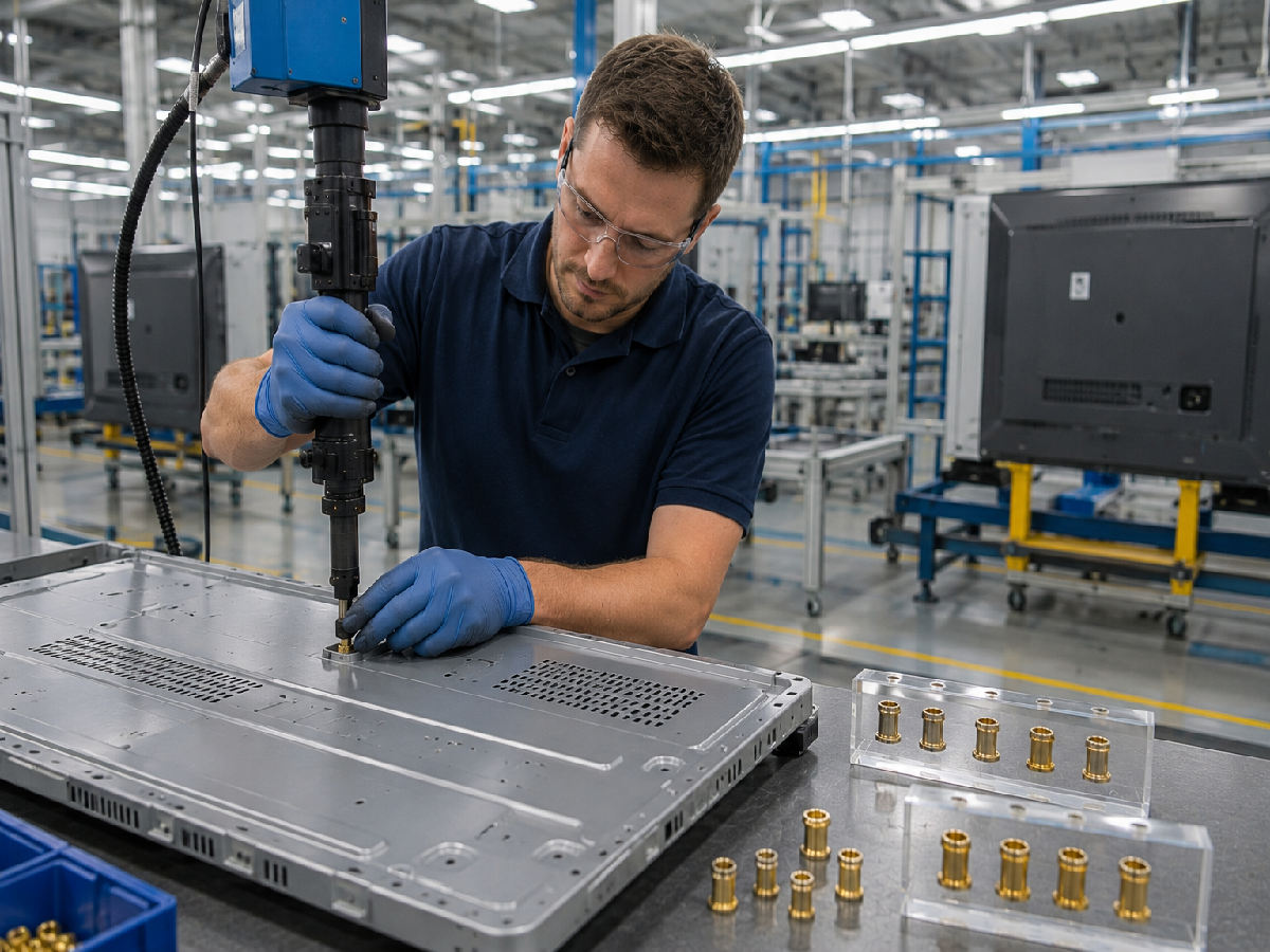
Before approving a second source for threaded inserts for plastic, consider defining:
approved drawing revision;
insert type;
thread size and pitch;
thread tolerance/class where specified;
insert length;
outside diameter;
external retention geometry;
material;
surface treatment;
polymer type and grade;
glass-fill percentage where applicable;
boss dimensions;
receiving-hole dimensions;
installation method;
installation depth;
pull-out requirements where applicable;
torque-out requirements where applicable;
operating temperature;
environmental requirements;
inspection requirements;
sample-validation requirements;
packaging;
production quantity;
estimated annual usage.
For technical review and quotation, provide as much of the following information as applicable:
2D drawing;
3D CAD model where available;
existing or competitor part number;
physical sample for cross-reference projects;
required internal thread;
insert dimensions;
thermoplastic resin and grade;
reinforcement percentage where applicable;
boss outside diameter;
receiving-hole diameter and depth;
installation method;
mating screw specification;
required tightening torque where specified;
pull-out requirement where specified;
torque-out requirement where specified;
operating temperature;
environmental exposure;
inspection or documentation requirements;
sample quantity;
production quantity;
estimated annual usage.
JUXIN FASTENERS can use this information to evaluate insert configuration, material and dimensional requirements, installation compatibility,
cross-reference feasibility, sample needs, and the appropriate production sourcing route.
For engineering teams, a useful selection path is:
Polymer → Joint Requirement → Boss Geometry → Insert Type → Installation Method → Screw Interface → Load Requirement → Environment → Validation
For procurement teams, the sourcing path continues:
Drawing / Existing Insert → Critical Characteristic Review → Material & Geometry Cross-Reference → Installation Trial → Functional Validation → Second-Source Approval → Production RFQ
The objective is not simply to place a metal thread inside plastic.
The objective is to create a reliable system in which the insert geometry, polymer, boss, installation process, mating screw, and service load work together throughout the intended product life.
Email: info@juxinfasteners.com
Website: www.juxinfasteners.com
 MORE NEWS
Sep. 30, 2026
Sep. 30, 2026
Sep. 30, 2026
Contact Us
Tel.:
+86 020 8621 0320
+86 020 3121 6067
E-mail:
Technical Support:
Navigation
SEND INQUIREY