
Call Us
+86 136 6007 9809
Call Us
+86 136 6007 9809

Sep. 30, 2026
Thin sheet metal creates a difficult fastening problem when engineers need a permanent threaded mounting point but cannot accept a visible bolt head,
through-hole, loose nut, or excessive welding distortion on the opposite side of the panel.
This challenge appears in:
electronics enclosures;
industrial control cabinets;
commercial HVAC equipment;
food-processing equipment;
laboratory equipment;
railway interior assemblies;
appliance housings;
automation equipment;
architectural sheet-metal assemblies.
Capacitor discharge (CD) weld studs provide one method of attaching threaded studs and related weld components to relatively thin
conductive sheet metal using a very short welding cycle and highly localized heat input.
Compared with longer-duration welding processes, properly developed CD stud welding can significantly reduce thermal distortion and visible backside effects.
However:
CD welding should not be treated as an automatic “no-mark” process.
Backside appearance depends on the complete relationship between stud geometry, sheet thickness, material, surface condition,
welding energy, equipment settings, fixturing, and cosmetic acceptance criteria.
JUXIN FASTENERS supplies standard and drawing-based CD weld studs and related weld-fastening components for industrial OEM and sheet-metal fabrication programs,
supporting dimensional review, material confirmation, sample evaluation, and second-source development.
Capacitor discharge stud welding stores electrical energy in a capacitor bank and releases that energy rapidly during the welding cycle.
A typical CD weld stud incorporates a small ignition tip at the weld end.
During the welding sequence:
electrical energy is discharged through the stud and workpiece;
the ignition tip initiates the arc;
the stud weld face and a localized area of the sheet surface melt;
the stud is driven into the molten interface;
the joint solidifies rapidly.
The welding event occurs over a very short period compared with many conventional arc-welding processes.
The practical engineering advantage is:
High Localized Energy + Short Weld Duration = Reduced Total Heat Input
This characteristic makes CD stud welding particularly useful for relatively thin sheet and applications where controlling distortion is important.
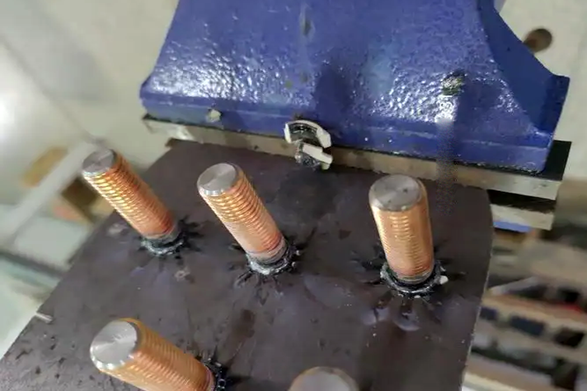
Traditional through-bolting requires access to both sides of the assembly.
Tapped holes require enough parent-material thickness for adequate thread engagement.
Weld nuts may require larger weld zones.
Other welding processes may introduce more heat into the surrounding panel.
CD studs create a permanent male threaded attachment point directly on the sheet.
Potential benefits include:
one-sided final assembly;
elimination of visible through-holes;
reduced loose hardware;
rapid installation;
compatibility with automated production;
relatively low overall heat input;
reduced post-weld finishing in suitable applications.
The suitability of the process must still be validated for the actual joint.
One of the main reasons engineers search for CD weld studs is the need to protect the visible side of a panel.
The engineering question should not be:
“Does CD welding leave zero marks?”
A better question is:
“Can the selected stud, sheet and welding process meet the allowable backside appearance requirement?”
Possible backside effects can include:
slight discoloration;
localized heat tint;
surface witness;
shallow deformation;
distortion;
burn-through in an improperly developed process.
The risk depends on several interacting variables.
Thicker sheet generally provides more thermal and structural margin, but a universal sheet-thickness ratio should not be applied to every CD welding application.
Required sheet thickness depends on factors such as:
stud weld-base diameter;
stud material;
sheet material;
weld energy;
equipment;
required joint strength;
backside cosmetic requirement;
sheet stiffness;
surface condition.
For this reason, JUXIN recommends evaluating the actual stud-to-sheet combination rather than relying on a single generic ratio.
For cosmetic applications, production-representative weld trials are especially important.
Another important distinction is:
Thread Diameter ≠ Weld-Base Diameter
A threaded CD stud may incorporate a weld-end geometry or flange that differs from its nominal thread diameter.
When evaluating:
sheet thickness;
weld energy;
edge distance;
mechanical strength;
backside appearance,
the actual weld-interface geometry matters.
Engineers should therefore use the component drawing rather than selecting the welding process solely from the thread designation.
The ignition tip is a functional welding feature, not a cosmetic detail.
Its geometry influences arc initiation and weld consistency.
Important characteristics can include:
tip height;
tip diameter;
concentricity;
weld-face geometry.
Variation in these features can change the welding response even when two studs have the same thread size and overall length.
This becomes especially important in high-volume automated welding.
Flanged CD weld studs incorporate an enlarged weld-end area.
Depending on the design, a flange can provide:
increased weld interface area;
geometry suitable for the specified joint;
improved handling characteristics;
features useful for automated feeding and positioning.
The flange dimensions should be treated as functional dimensions during second-source qualification.
Two M5 studs with different flange geometries should not automatically be treated as interchangeable.
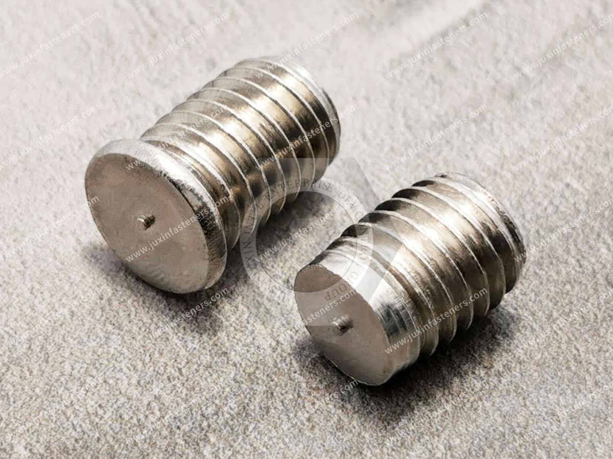
Non-flanged configurations can be useful where surrounding clearance is restricted.
Potential applications include locations near:
bends;
formed walls;
adjacent components;
narrow channels;
compact sheet-metal structures.
The reduced base geometry changes the weld interface, so weld settings and mechanical performance should be validated for the specific design.
CD welding is not limited to conventional externally threaded studs.
Depending on the application and component design, weld-fastening systems can include:
externally threaded studs;
internally threaded components;
pins;
other application-specific weld components.
The correct geometry should be selected according to the final assembly function rather than welding convenience alone.
Common stud materials can include application-appropriate:
low-carbon steel;
stainless steel;
aluminum alloys.
Material selection should consider both:
Weldability and Final Service Environment
The stud material does not always need to be exactly the same grade designation as the sheet,
but the combination must be metallurgically compatible with the selected CD welding process and suitable for the service environment.
Stainless steel studs are commonly considered for stainless sheet-metal assemblies where corrosion resistance and appearance are important.
Applications can include:
food-processing equipment;
laboratory equipment;
commercial kitchens;
equipment enclosures;
architectural metalwork.
The actual stainless grade should be selected according to:
corrosion environment;
mechanical requirements;
customer specification;
welding compatibility.
A stainless designation alone does not establish suitability.
Aluminum CD welding requires careful control of:
alloy compatibility;
surface oxide;
cleanliness;
welding parameters.
Aluminum naturally develops a surface oxide layer that affects electrical and welding behavior.
If the sheet has been anodized, painted, or otherwise covered with a non-conductive layer, the weld zone generally requires an appropriate process strategy.
Do not assume that a stud can simply be welded directly through any decorative or protective surface treatment.
Low-carbon steel studs can be used with suitable steel sheet applications.
Depending on specification, steel CD studs may use an application-appropriate surface condition or coating.
Any coating associated with the welding interface should be evaluated for:
electrical behavior;
weldability;
corrosion protection;
post-weld performance.
The finish should never be selected independently from the welding process.
Because CD welding occurs rapidly, the process does not provide unlimited time to overcome poor surface conditions.
Potential problems include:
heavy oil;
grease;
rust;
scale;
paint;
powder coating;
anodizing;
non-conductive films.
The actual weld zone should provide a condition compatible with reliable electrical contact and fusion.
This creates an important production question:
At What Stage in the Finishing Process Will the Stud Be Welded?
The manufacturing sequence can affect both welding and appearance.
Potential advantages can include easier access to conductive base metal.
However, the later coating process may affect:
threads;
electrical grounding requirements;
stud appearance;
dimensional interfaces.
This may protect previously finished areas from later processing, but non-conductive coatings at the weld location can interfere with the welding process.
The correct sequence depends on:
coating type;
masking strategy;
appearance requirements;
electrical requirements;
production flow.
These processes should not be treated as interchangeable simply because both attach a stud to sheet metal.
Often considered when:
relatively thin sheet is involved;
localized heat input is desirable;
rapid stud installation is required;
visible-surface control is important;
dedicated CD welding equipment is available.
Resistance projection welding uses engineered projections and resistance-generated heat at the interface.
It may be selected where:
the assembly is designed around resistance welding;
sheet and stud geometry support the process;
production uses suitable resistance-welding equipment;
specific push-out, torque or structural requirements favor the joint architecture.
The correct choice depends on the actual assembly and production process.
Self-clinching studs create mechanical attachment through controlled displacement of sheet material.
CD studs create a metallurgical weld.
Self-clinching studs may be attractive when:
welding heat is undesirable;
the sheet supports the required clinching process;
press access is available.
CD studs may be attractive when:
welding is acceptable;
a welded attachment is preferred;
the sheet and stud materials are suitable;
the production process already supports stud welding.
Neither technology is universally superior.
Through-bolting can provide a straightforward mechanical joint but requires:
a hole through the panel;
access to both sides;
additional loose hardware;
visible hardware on the opposite side in many designs.
A CD weld stud can eliminate the through-hole and permanently locate the male thread.
This can be useful for enclosure and cosmetic-panel applications.
Another oversimplification is:
“The weld is always stronger than the stud.”
A properly developed weld can provide excellent strength, but the actual failure mode depends on:
stud material;
stud geometry;
sheet material;
sheet thickness;
weld parameters;
loading direction;
edge distance;
joint design.
Possible destructive-test failure locations can include:
stud shank;
weld interface;
parent sheet;
surrounding sheet deformation.
The correct acceptance criterion should come from the application requirement.
A stud can experience different load directions.
Attempts to pull the stud away from the sheet.
Acts parallel to the sheet surface.
Many real assemblies experience a combination of both.
Engineers should therefore define the expected loading condition rather than specifying only a generic “weld strength.”
Stud location can influence both welding and panel performance.
Consider clearance from:
sheet edges;
bends;
stamped features;
adjacent studs;
holes;
enclosure walls.
Insufficient surrounding material can affect:
local stiffness;
distortion;
mechanical loading;
welding-gun access.
Stud location should therefore be evaluated during enclosure design rather than added at the end of the project.
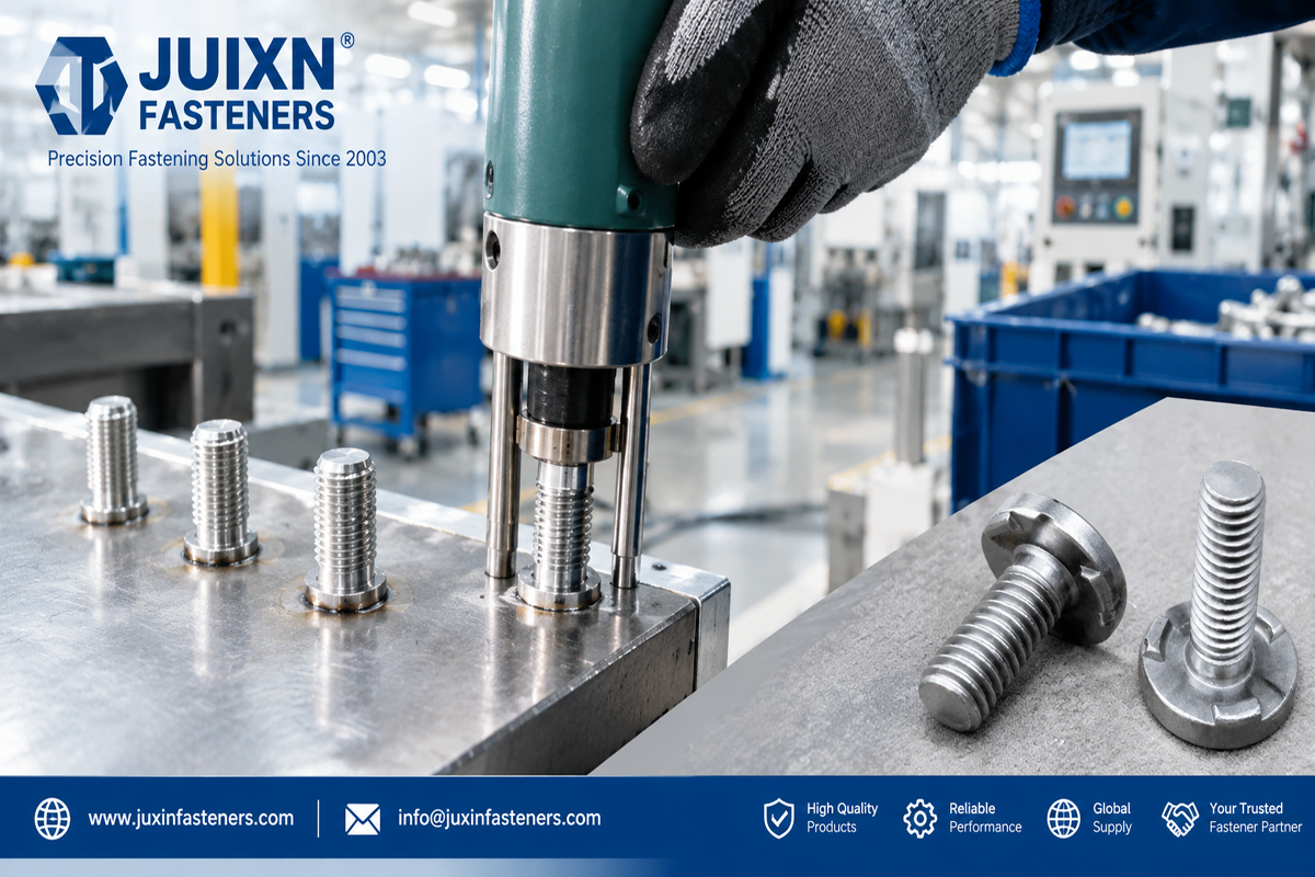
High-volume manufacturing can use automated or semi-automated stud-feeding systems.
For these applications, fastener consistency affects more than the final joint.
Important characteristics can include:
overall length;
flange diameter;
straightness;
ignition-tip consistency;
thread geometry;
feeding orientation;
packaging.
A dimension that appears non-critical in a manual welding process can become important in an automated bowl feeder or welding head.
A replacement CD stud can match:
thread size;
length;
material;
general appearance
and still behave differently in production.
Potential differences include:
ignition-tip geometry;
flange dimensions;
weld-base geometry;
material condition;
dimensional tolerance;
surface condition.
Therefore:
Same Thread + Same Length ≠ Same Welding Performance
This is especially important when replacing an existing production part.
For second-source development, provide where available:
existing supplier part number;
2D drawing;
physical sample;
thread size;
stud length;
flange dimensions;
weld-base geometry;
material;
finish;
parent sheet material;
sheet thickness;
welding equipment;
required mechanical performance;
cosmetic backside requirement.
A drawing plus application information is more useful than appearance alone.
Depending on the application, qualification may include:
dimensional inspection;
thread gauging;
material verification;
welding trials;
visual weld inspection;
bend testing;
tensile testing;
shear testing;
destructive pull testing;
backside appearance evaluation.
The required test plan should reflect the function of the part.
Not every CD weld stud program requires every test.
CD weld studs may be specified according to applicable international standards such as ISO 13918 or customer-specific drawings, depending on the component and program.
However, referencing a standard does not automatically define every application requirement.
OEM drawings may additionally control:
dimensions;
material;
thread tolerance;
surface condition;
weld-end geometry;
inspection;
traceability;
packaging.
For custom components, the customer drawing should clearly identify critical-to-function characteristics.
Procurement and supplier-development teams should compare:
thread size and pitch;
thread tolerance;
overall length;
flange diameter;
flange thickness;
weld-base geometry;
ignition-tip geometry;
material;
finish;
dimensional tolerances;
parent sheet compatibility;
welding equipment compatibility;
mechanical requirements;
backside appearance requirements;
packaging and automated-feed requirements;
inspection documentation;
traceability.
This avoids approving a visually similar component that changes the welding process.
For faster engineering review and quotation, provide:
2D drawing or 3D CAD model;
existing part number where applicable;
physical sample where available;
thread size and pitch;
stud length;
flange dimensions;
stud material;
required finish;
parent sheet material;
exact sheet thickness;
surface condition or coating;
required tensile or shear performance where specified;
cosmetic backside requirement;
welding equipment or process information;
manual or automated installation;
estimated annual usage;
order quantity;
sample quantity;
inspection requirements;
material documentation requirements;
traceability requirements.
JUXIN FASTENERS can use this information to evaluate standard-product availability, drawing-based manufacturing, dimensional cross-reference, sample requirements, and production feasibility.
For engineering teams:
Sheet Material → Sheet Thickness → Surface Requirement → Stud Geometry → Material Compatibility
→ Welding Process → Parameter Development → Weld Testing → Assembly Validation
For procurement and supplier-development teams:
Existing Stud / Drawing → Critical Dimensions → Material → Weld-End Geometry → Sample Cross-Reference
→ Welding Trial → Mechanical & Cosmetic Validation → Second-Source Approval → Production RFQ
The central engineering principle is:
CD weld-stud performance comes from the complete stud–sheet–surface–equipment–process system, not from the stud alone.
Selecting the correct stud therefore requires engineers and procurement teams to evaluate sheet thickness, material, weld-base geometry,
ignition-tip consistency, surface condition, loading, backside appearance, welding equipment, automation requirements, and qualification criteria together.
Email: info@juxinfasteners.com
Website: www.juxinfasteners.com
 MORE NEWS
Sep. 30, 2026
Sep. 30, 2026
Sep. 30, 2026
Contact Us
Tel.:
+86 020 8621 0320
+86 020 3121 6067
E-mail:
Technical Support:
Navigation
SEND INQUIREY