
Call Us
+86 136 6007 9809
Call Us
+86 136 6007 9809

Sep. 30, 2026
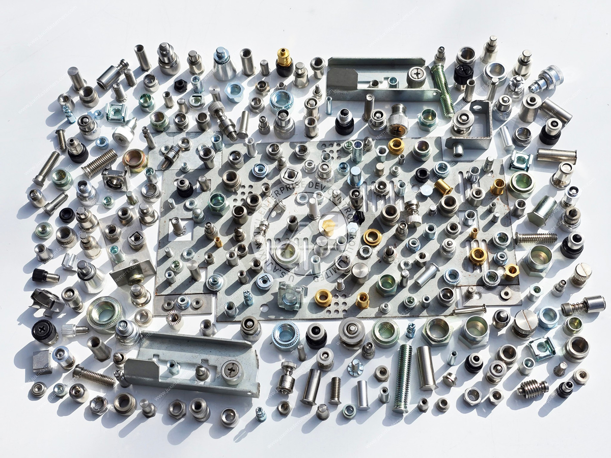
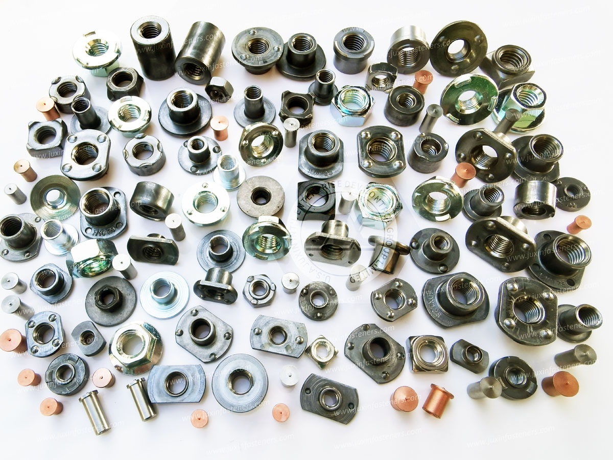
Projection weld nuts create permanent internal threads on sheet-metal and fabricated structures by resistance welding engineered projections on the nut to the parent material.
They are widely used in:
automotive body structures;
EV battery enclosures;
commercial vehicles;
heavy equipment;
agricultural machinery;
railway equipment;
industrial enclosures;
appliances;
HVAC assemblies;
material-handling equipment.
Their value is not simply that they are “nuts that can be welded.”
A projection weld nut combines three functions:
Threaded Fastener + Positioning Interface + Resistance-Welding Component
For this reason, successful performance depends on much more than thread size.
The nut geometry, weld projections, pilot or locating features, parent sheet, surface condition, welding current, electrode force, weld time, tooling, and final assembly torque all interact.
JUXIN FASTENERS supplies standard and drawing-based projection weld nuts, including DIN 929 hex weld nuts, DIN 928 square weld nuts,
flange weld nuts, piloted weld nuts, and other custom projection-weld fastening components for OEM and Tier-1 manufacturing programs.
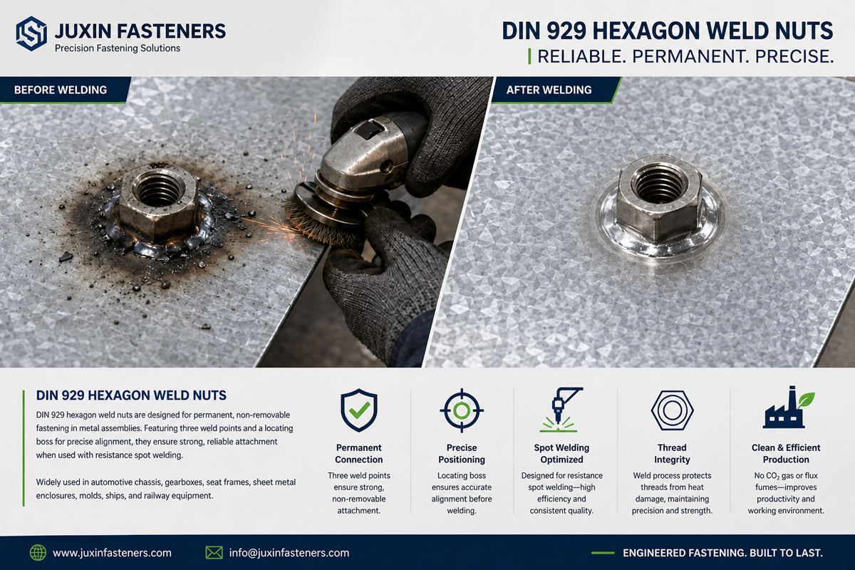
A projection weld nut incorporates engineered raised features on its welding face.
These features are known as weld projections.
During resistance welding, the nut and parent sheet are clamped between electrodes.
Electrical current passes through the assembly.
Because the initial contact area is concentrated at the projections, electrical resistance and current density generate localized heating at those interfaces.
Under controlled electrode force, the projections heat, deform and collapse while the contacting materials form localized welded zones.
The engineering principle is:
Projection Geometry + Current + Time + Electrode Force + Parent Material = Weld Formation
Changing one variable can change the resulting weld.
The projections are functional manufacturing features.
Their:
height;
width;
shape;
position;
symmetry;
number;
dimensional consistency
can influence current distribution and weld formation.
If one projection is significantly different from the others, it may contact the sheet earlier and carry a disproportionate amount of current.
The result can be uneven welding.
Possible symptoms include:
one strong weld and several weak welds;
excessive local expulsion;
nut tilt;
inconsistent push-out strength;
inconsistent torque-out performance.
This is why projection dimensions should be treated as critical-to-function characteristics during second-source qualification.
DIN 929-style hexagon weld nuts are widely used for creating permanent metric internal threads on weldable assemblies.
Depending on size and design, important characteristics include:
thread size;
body dimensions;
nut height;
locating/pilot geometry;
weld projections;
material;
surface condition.
Applications can include:
automotive brackets;
seat structures;
chassis assemblies;
equipment frames;
battery-related structures;
fabricated housings.
The hexagonal external form also provides useful geometry for handling and manufacturing, but the actual weld performance is determined by the complete nut-to-sheet interface.
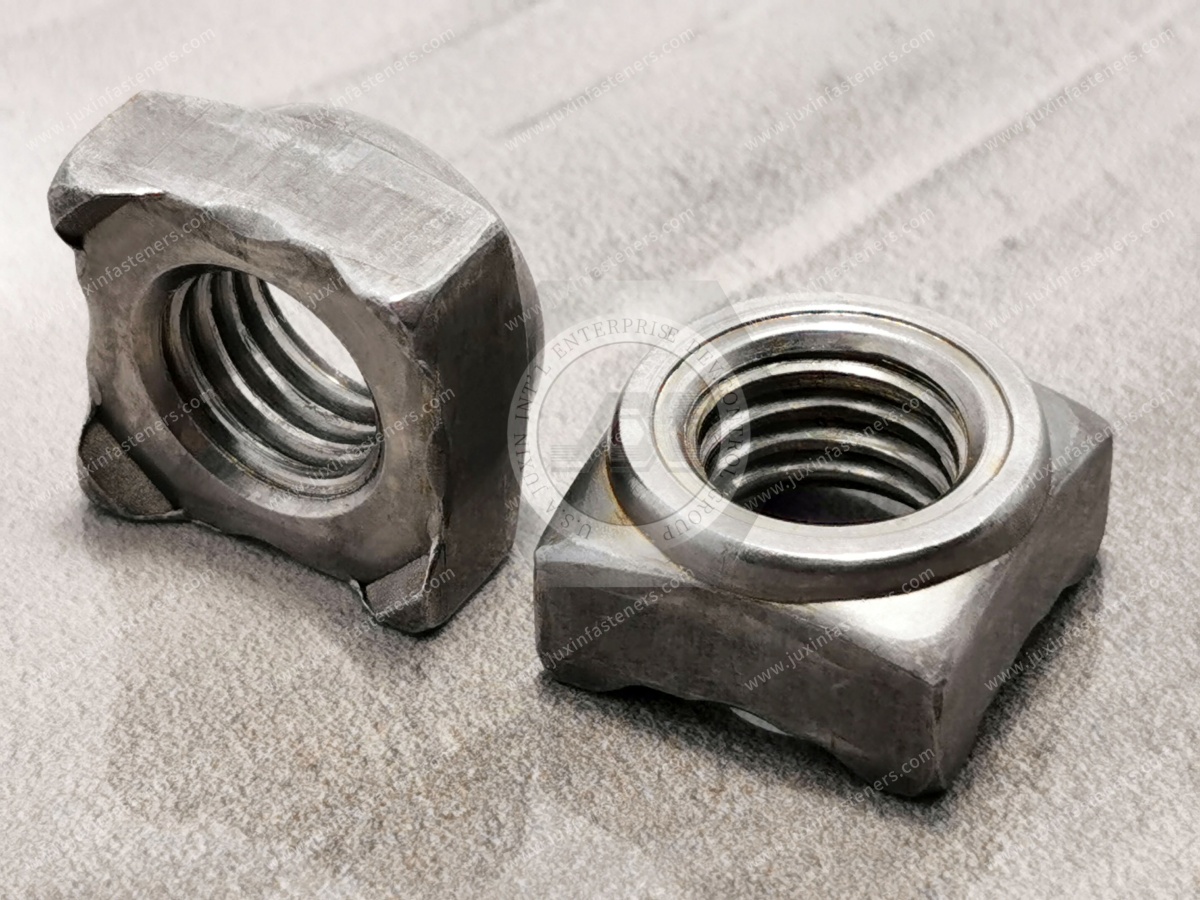
DIN 928-style square weld nuts provide another established projection-weld nut architecture.
Their square body geometry can be useful for:
positioning;
fixture design;
component handling;
specific assembly packaging requirements.
DIN 928 and DIN 929 should not be selected simply by assuming that one is universally “stronger” than the other.
The correct selection depends on:
available space;
thread size;
sheet geometry;
welding process;
loading;
assembly design;
customer standard.
Flanged weld nuts provide an enlarged body or bearing geometry around the threaded feature.
Depending on design, this can support:
positioning;
load distribution;
welding-interface requirements;
automated handling.
Flange diameter, thickness and projection geometry should be confirmed from the actual component drawing.
Some weld nuts incorporate a pilot or locating feature that interfaces with a prepared hole in the parent sheet.
The pilot can assist with:
nut positioning;
concentricity;
assembly repeatability;
fixture location.
However:
Pilot Geometry ≠ Automatic Thread Protection
Thread contamination during welding depends on the complete nut design, welding process, electrode/tooling arrangement and spatter/expulsion control.
The pilot should therefore be treated primarily as part of the nut-to-sheet locating interface unless the specific design provides additional functions.
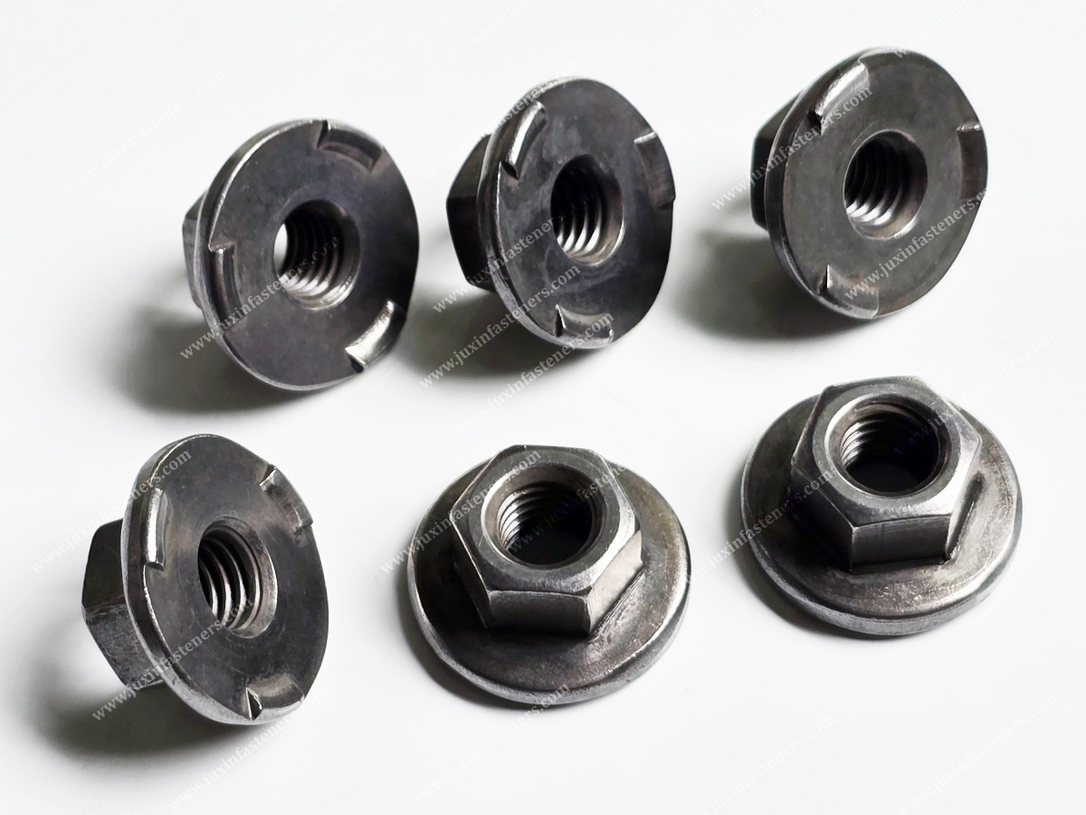
The relationship between the pilot and sheet hole is critical.
If clearance is too large:
positioning accuracy can decrease;
concentricity may be affected;
assembly location can vary.
If clearance is too small:
insertion can become difficult;
tolerance stack-up can interfere with production;
the nut may not seat correctly.
For drawing-based weld nuts, engineers should specify or confirm:
pilot outside diameter;
sheet hole diameter;
dimensional tolerances;
positional tolerance.
A conventional nut can theoretically be attached by several welding methods.
A purpose-designed projection weld nut, however, incorporates geometry specifically intended to control where resistance-welding energy is concentrated.
This supports:
repeatable production;
controlled weld locations;
automated welding;
high-volume manufacturing.
For automotive and other high-volume programs, repeatability can be as important as nominal joint strength.
Projection welding requires a process window.
Potential results include:
incomplete projection collapse;
inadequate fusion;
low push-out strength;
low torque-out resistance;
unstable production results.
Potential results include:
metal expulsion;
excessive spatter;
sheet damage;
nut distortion;
electrode wear;
thread contamination;
inconsistent weld geometry.
Therefore:
More Current ≠ Better Weld
The objective is a validated welding schedule for the actual nut, sheet and equipment.
Electrode force is another major process variable.
Too little force can contribute to unstable electrical contact and excessive expulsion.
Excessive force can prematurely deform projections or alter the intended heating sequence.
The welding process therefore needs to balance:
Current + Weld Time + Electrode Force
rather than controlling only one parameter.
Projection collapse provides useful information about process stability.
After welding, inconsistent seating or visible nut tilt can indicate problems involving:
projection variation;
electrode alignment;
sheet flatness;
force distribution;
welding parameters.
For high-volume production, dimensional consistency of the supplied nut can directly influence the size of the usable welding process window.
The parent sheet must support both:
the welding process; and
the mechanical loads transferred through the final threaded joint.
Very thin sheet can become the limiting element even when the weld itself is adequate.
Possible failure modes include:
local sheet deformation;
tearing;
pull-through;
distortion around the weld zone.
There is no universal sheet-thickness rule for every projection weld nut.
The correct combination depends on nut size, material, sheet grade, welding process and required mechanical performance.
Projection weld nuts are commonly used with weldable sheet steels, but material compatibility must be reviewed for the actual application.
Important factors include:
carbon content;
alloy composition;
hardness;
coating;
sheet thickness;
surface condition.
A nut that performs well on one sheet grade may require a different welding schedule on another.
Automotive and industrial sheet may be:
zinc coated;
zinc-alloy coated;
pretreated;
otherwise surface protected.
Coatings can affect electrical contact, heat generation, electrode condition and weld behavior.
Therefore, qualification should use production-representative sheet wherever possible.
Testing a nut on bare laboratory sheet may not reproduce the production process used on coated panels.
The nut's own surface condition can also affect welding.
Surface treatment should be selected with consideration for:
resistance welding;
corrosion protection;
electrical behavior;
customer specifications;
post-weld environment.
A coating should not be specified solely for corrosion resistance without evaluating its effect on the welding process.
A weld nut performs two separate functions:
It Must Weld Correctly
and
It Must Still Function as a Threaded Fastener
Both matter.
Thread requirements can include:
thread size;
pitch;
tolerance class;
GO/NO-GO gauging;
assembly fit.
For production validation, thread function should be evaluated after welding when the process has the potential to influence thread condition.
Thread problems after welding can result from:
weld spatter;
expulsion;
nut distortion;
electrode misalignment;
excessive heat;
incorrect tooling;
dimensional variation.
If a mating bolt cannot assemble reliably after welding, the component has failed its functional purpose even if the weld itself appears acceptable.
Push-out testing evaluates resistance to axial removal of the welded nut from the parent sheet.
It can help assess the integrity of the nut-to-sheet attachment.
Results depend on:
nut geometry;
number of projections;
sheet material;
sheet thickness;
welding parameters;
test method.
A push-out value should therefore always be interpreted with the test configuration.
Torque-out testing evaluates resistance to rotational failure of the welded nut relative to the sheet.
This is particularly relevant because the nut must resist torque when the mating bolt is installed or removed.
A weld can show acceptable axial retention yet still perform poorly under rotational loading.
Therefore:
Push-Out Strength ≠ Torque-Out Strength
Both may need to be validated depending on the assembly.
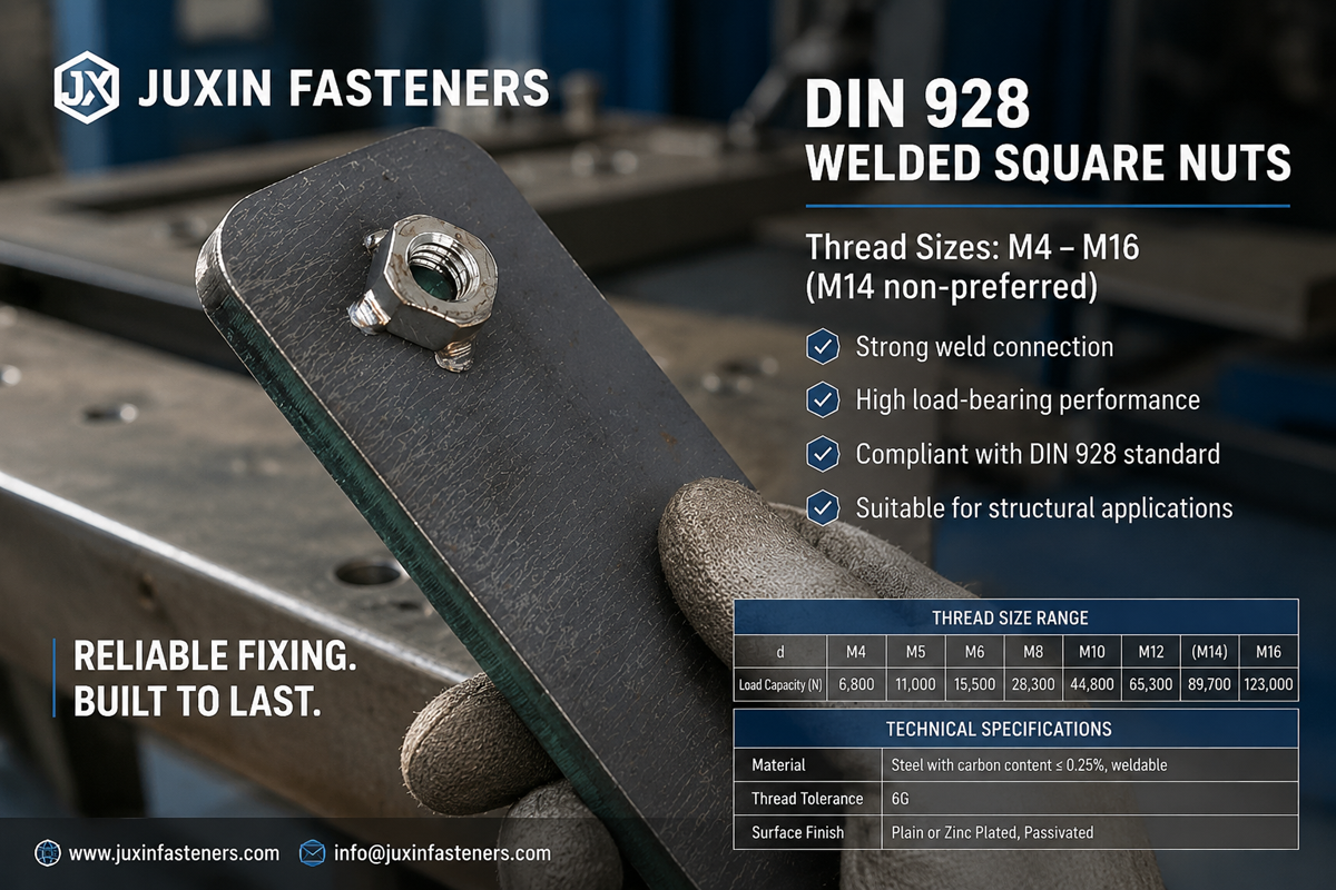
The tightening torque applied to the final bolt creates a complex joint load.
A laboratory torque-out test is a qualification or comparison method for the welded attachment.
The two values should not automatically be treated as interchangeable.
Design engineers should define acceptance criteria according to the actual assembly.
Expulsion occurs when molten material is ejected from the weld interface.
Potential causes can include:
excessive current;
insufficient electrode force;
excessive weld time;
poor projection consistency;
surface contamination;
poor electrode alignment;
inappropriate material/coating combinations.
Occasional spatter should not simply be corrected by reducing current without understanding the cause.
The complete process should be evaluated.
Even a dimensionally correct weld nut can produce inconsistent results if the welding equipment is misaligned.
Electrodes should apply force in a controlled manner.
Poor alignment can lead to:
uneven projection contact;
nut tilt;
asymmetric weld formation;
accelerated electrode wear.
Supplier qualification and production-process qualification are therefore related but separate activities.
Automotive and high-volume assembly lines frequently use automated nut feeding.
In these systems, dimensions that do not directly affect static joint strength may still be critical to production.
Examples include:
body width;
overall height;
flange geometry;
pilot geometry;
burr condition;
orientation features;
dimensional consistency.
Packaging can also affect automated feeding.
A qualified second-source part should therefore be evaluated not only in the welding station but also through the feeding and handling system.
Projection weld nuts are widely used throughout automotive structures.
Potential locations include:
body brackets;
seat structures;
chassis-related components;
interior mounting structures;
underbody assemblies;
battery-related structures.
Different locations can have different requirements for:
strength;
corrosion resistance;
coating;
welding;
traceability.
The application should therefore be identified during RFQ review.
Battery enclosures can require permanent threaded mounting points for:
covers;
brackets;
structural components;
internal hardware;
peripheral assemblies.
Depending on enclosure material and architecture, possible fastening methods can include:
projection weld nuts;
projection weld studs;
self-clinching fasteners;
rivet nuts;
other inserts.
Projection welding should only be selected where the enclosure material and production process support the required welding system.
Heavy equipment structures experience:
vibration;
shock;
dirt;
moisture;
high mechanical loads.
Weld nuts can eliminate loose backside hardware and provide permanent threaded attachment points on fabricated structures.
Mechanical validation should reflect the actual load and service environment.
Railway equipment may use weld nuts in:
equipment frames;
electrical cabinets;
brackets;
interior structures;
equipment housings.
Project-specific requirements for vibration, corrosion, material, traceability and documentation should be evaluated separately from the basic DIN dimensional standard.
Both technologies create permanent internal threads.
But their attachment principles differ.
Attachment: Resistance welding
Potential advantages where appropriate:
metallurgical attachment;
high-volume automated welding;
established automotive manufacturing processes.
Attachment: Mechanical cold-flow installation
Potential advantages where appropriate:
no welding heat;
useful for suitable thin-sheet materials;
compatible with press-based installation.
Selection should follow the actual sheet, manufacturing process and load requirement.
Rivet nuts are particularly useful where installation access is available from only one side.
Projection weld nuts require a suitable welding process and electrode/tooling arrangement.
For a closed structure where rear-side welding access is impossible, a rivet nut may provide a different manufacturing solution.
These technologies should therefore be selected based on assembly architecture rather than treated as direct substitutes.
Two DIN 929 or DIN 928 weld nuts can appear almost identical.
But important differences may exist in:
projection height;
projection shape;
projection location;
pilot dimensions;
body dimensions;
material;
hardness;
surface condition;
thread tolerance;
burr condition.
These differences can affect welding behavior.
Therefore:
Dimensional Similarity ≠ Welding Equivalence
When qualifying an alternative supplier, procurement teams often focus on:
thread size;
nut width;
height.
For projection weld nuts, this is incomplete.
Projection geometry should also be compared because it directly influences the welding process.
A new source may require process validation even if the overall nut dimensions match the existing component.
A robust second-source process can follow:
Existing Part → Drawing Review → Dimensional Comparison → Material Review → Projection Geometry Review
→ Sample Production → Welding Trial → Push-Out / Torque-Out Testing → Assembly Validation → Production Approval
For automated programs, add:
Feeding & Handling Validation
before final approval.
For faster engineering and commercial review, provide:
2D drawing or 3D CAD model;
existing supplier part number where applicable;
physical sample where available;
standard designation where applicable;
thread size and pitch;
thread tolerance requirement;
nut body dimensions;
pilot dimensions;
projection dimensions;
parent sheet material;
sheet thickness;
sheet coating or surface condition;
nut material;
required nut finish;
welding equipment information where available;
required push-out performance;
required torque-out performance;
final bolt tightening torque where relevant;
automated feeding requirements;
estimated annual usage;
production batch quantity;
sample quantity;
inspection requirements;
material documentation;
traceability requirements.
JUXIN FASTENERS can use these inputs to evaluate standard DIN-style products, drawing-based weld nuts, dimensional cross-reference, sample requirements and custom production feasibility.
For engineering teams:
Parent Sheet → Thread Requirement → Nut Geometry → Pilot/Hole Interface → Projection Design
→ Material & Surface → Welding Schedule → Mechanical Testing → Assembly Validation
For procurement and supplier-development teams:
Existing Part / Drawing → Critical Dimensions → Material → Projection Geometry → Sample
→ Weld Trial → Push-Out / Torque-Out Validation → Feeding Validation → Second-Source Approval → Production RFQ
The most important principle is:
A projection weld nut is both a threaded fastener and a welding-process component.
Its performance cannot be evaluated from thread size or DIN designation alone.
Reliable production requires engineers and procurement teams to evaluate the complete relationship between the nut geometry,
projections, pilot, parent sheet, material, coating, welding current, weld time, electrode force, tooling, mechanical loads, thread function,
automation system, and qualification requirements.
Email: info@juxinfasteners.com
Website: www.juxinfasteners.com
 MORE NEWS
Sep. 30, 2026
Sep. 30, 2026
Sep. 30, 2026
Contact Us
Tel.:
+86 020 8621 0320
+86 020 3121 6067
E-mail:
Technical Support:
Navigation
SEND INQUIREY