
Call Us
+86 136 6007 9809
Call Us
+86 136 6007 9809

Sep. 22, 2026
In precision sheet-metal fabrication, enclosure design, chassis engineering, and equipment manufacturing,
joint reliability depends not only on the selected fastener but also on where the mounting hole is positioned.
When design engineers specify edge-mounted spring fasteners such as U-nuts, J-nuts, clip-on nuts, barrel clip nuts,
and enclosed spring nuts, thread size and panel thickness are only part of the design equation.
Edge distance, hole setback, bend clearance, throat depth, hole diameter,
and manufacturing tolerances determine whether the fastener can seat correctly and whether the mating screw can enter the thread without interference.
Incorrect hole placement can cause:
Panel-edge deformation or breakout
Clip-on nut slippage during screw installation
Incomplete clip seating
Screw-to-thread misalignment
Cross-threading or thread stripping
Angular loading on the spring nut
Reduced clamp-load consistency
Assembly-line rework
Premature fatigue around the punched hole
Inability to replace or service the panel efficiently
Effective edge distance and hole setback engineering aligns the sheet-metal geometry with the actual clip-on nut profile.
It also provides sufficient material around the hole, adequate clearance from formed bends, and enough positional tolerance for stamping, laser cutting, bending, coating, and final assembly.
The nominal centerline setback for an edge-mounted clip-on nut should normally correspond to the fastener’s functional throat depth: the distance from the clip entry edge to the centerline of its threaded feature.
However, throat-depth matching alone is not sufficient.
The final hole location must also account for:
Panel clearance-hole diameter
Remaining material between the hole and the free edge
Distance from the hole to the bend tangent
Panel thickness and material condition
Clip geometry and available float
Hole-making and bending tolerances
Burr direction and edge condition
Coating thickness
Screw-entry alignment
Required clamp load and service environment
There is no universal edge-distance value that applies to every U-nut, J-nut, panel material, hole diameter, and flange geometry.
The correct dimension must be derived from the selected fastener drawing and verified in the intended sheet-metal assembly.
For an edge-mounted clip-on nut, hole setback is generally the distance from the reference edge of the sheet-metal flange to the centerline of the clearance hole or screw-access hole.
Let:
= nominal centerline setback from the panel edge
= panel clearance-hole diameter
= remaining edge ligament between the hole and the free panel edge
For a circular hole:
This relationship is simple, but it is important because two designs with the same hole-center setback can have very different remaining edge strength if their hole diameters differ.
For example, if the nominal centerline setback is 12.0 mm:
With a 6.0 mm hole, the nominal edge ligament is 9.0 mm.
With an 8.0 mm hole, the nominal edge ligament is 8.0 mm.
With a 10.0 mm hole, the nominal edge ligament is only 7.0 mm.
Therefore, a setback dimension should never be evaluated without the associated hole diameter.
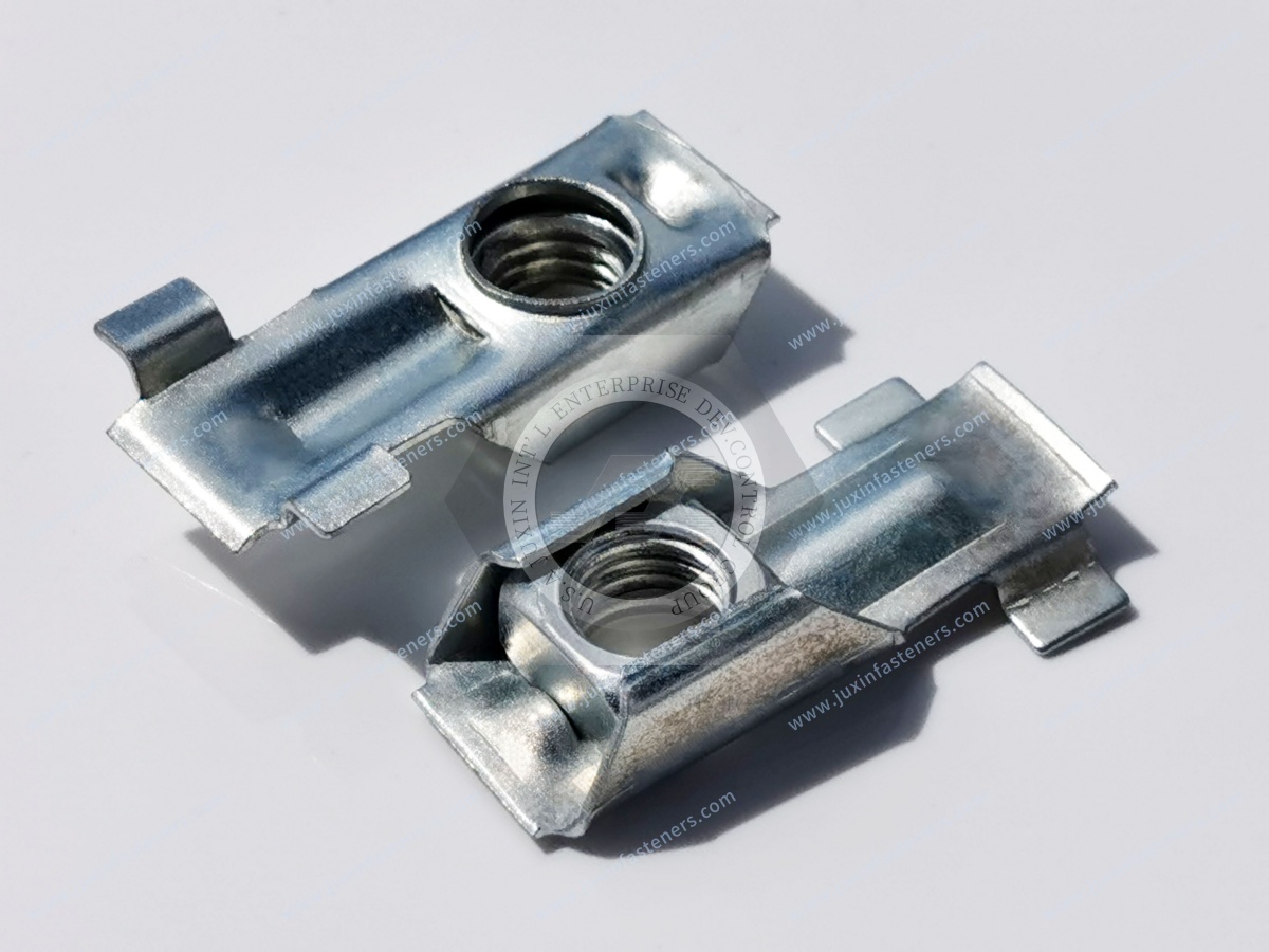
The terms “hole setback” and “edge distance” are sometimes used interchangeably, but engineering teams should distinguish them on drawings and in RFQs.
The distance from a defined panel edge to the hole centerline.
The shortest remaining material between the edge of the hole and the free edge of the panel.
The distance between the nearest edge of the hole or clip seating zone and the bend tangent or formed radius.
The functional reach of the clip-on nut from its entry edge to its threaded centerline.
The distance the clip must travel onto the panel before its locating and threaded features reach their intended positions.
Clearly defining these dimensions prevents ambiguity between the fastener supplier, sheet-metal fabricator, tooling supplier, quality team, and OEM assembly plant.
Every clip-on nut has a functional throat depth. This dimension controls how far the threaded feature sits from the panel edge after the clip is fully installed.
For correct assembly:
where:
= nominal sheet-metal hole setback
= clip-on nut throat depth to the thread centerline
The relationship is approximate because the final alignment may also depend on:
A floating or fixed thread feature
The geometry of the clip entry
A panel-locating lance or embossed feature
A slotted rather than circular clearance hole
Installation direction
Coating thickness
Panel-edge radius
The clip’s allowable seating range
Manufacturer-specific dimensional tolerances
The selected fastener drawing—not a generic catalog description—should be the controlling dimensional reference.
International standards can support drawing control, thread specification, material definition, coating requirements, and inspection methods.
They do not automatically establish one universal hole setback for every proprietary clip-on nut geometry.
Relevant engineering frameworks may include:
ISO 1101 for geometrical product specification and geometric tolerancing
ASME Y14.5 for dimensioning and tolerancing
ISO metric thread requirements, where applicable
ASME unified inch-thread requirements for UNC and UNF products
ISO 4042 for electroplated coating requirements on threaded fasteners, where applicable
ISO 10683 for non-electrolytically applied zinc-flake coating systems, where applicable
ASTM B117 for comparative salt-spray testing when specified as part of a coating validation plan
These standards help define how the product is specified and verified.
The actual clip throat depth, hole setback, seating envelope, and acceptable panel range remain dependent on the fastener design and application.
A production drawing should therefore combine recognized international drawing practices with the specific clip-on nut manufacturer’s dimensional data.
The sheet-metal clearance hole must align with the clip-on nut’s threaded feature closely enough for the mating screw to enter without contacting the panel-hole edge.
If the centerlines are offset, the screw may:
Strike the panel before reaching the thread
Enter the nut at an angle
Cross-thread during powered installation
Apply lateral force to the clip
Push the clip away from its seated position
Produce false torque before achieving the intended preload
A floating thread feature may absorb limited misalignment, but its available float should not be treated as a substitute for proper hole positioning.
The remaining ligament must resist local deformation during punching, clip installation, and screw tightening.
If the hole is too close to the free edge, the material may:
Bulge outward
Tear during punching
Crack after bending
Distort under clip spring pressure
Break out during high installation torque
Lose dimensional stability during repeated service
The acceptable ligament depends on panel material, thickness, temper, hole diameter, manufacturing method, load direction, and required service life.
A thin aluminum panel and a thicker high-strength steel panel should not automatically use the same rule.
The clip must sit on a sufficiently flat surface.
If the clip reaches into the formed bend radius:
The clip body may rock instead of seating flat.
The spring legs may spread unevenly.
The threaded feature may tilt.
Local contact pressure may damage the coating.
Screw installation may pull the fastener sideways.
The panel may appear assembled while the joint remains mechanically unstable.
The design must consider both the hole’s distance from the bend and the flat seating area required by the complete clip body.
A nominal edge ligament does not represent the minimum material that will remain on every production part.
For worst-case evaluation:
where:
= minimum possible edge ligament
= minimum permitted hole-center setback
= maximum permitted hole diameter
If the nominal setback is 12.0 mm with a tolerance of ±0.2 mm, and the hole diameter is 6.5 mm with a tolerance of +0.2/0 mm:
The design review should evaluate 8.45 mm, not the nominal ligament calculated from 12.0 mm and 6.5 mm.
This method is particularly important when the hole is positioned close to a free edge or when the panel is thin relative to the screw and hole diameter.
The final screw-to-thread alignment can be affected by several independent sources of variation:
Hole-position tolerance
Panel-edge trimming tolerance
Bend-position tolerance
Bend-angle variation
Springback after forming
Clip throat-depth tolerance
Clip seating variation
Panel-thickness variation
Coating buildup
Assembly positioning
Screw straightness and driver alignment
A conservative worst-case estimate can be expressed as:
The available accommodation of the joint—including clearance-hole allowance and any designed thread float—must exceed the expected total misalignment with an appropriate engineering margin.
A statistical root-sum-square method may be used by qualified engineering teams when the contributing variables are independent and the manufacturing process is stable and capable.
It should not replace worst-case analysis where safety, field service, or line-stop risk is significant.
Hole setback can only be controlled effectively if it is dimensioned from the correct datum.
A weak drawing may dimension the hole from an unrelated exterior feature while the clip is installed from a formed flange edge. This creates unnecessary tolerance accumulation.
For edge-mounted spring fasteners, the preferred functional datum is often the same physical edge or flange feature that stops and locates the clip during installation.
The engineering drawing should specify:
The functional locating edge
The hole position relative to that edge
The applicable positional tolerance
Bend location and angle
Flange width
Hole diameter and profile
Panel thickness
Burr direction, if functionally important
Coating condition at final inspection
Where appropriate, geometrical tolerancing under ISO 1101 or ASME Y14.5 can communicate the required relationship more reliably than multiple chained linear dimensions.
A flat edge offers the simplest geometry. The main considerations are throat-depth alignment, edge ligament, burr condition, and panel thickness.
A formed flange introduces bend radius, springback, flange-width tolerance, and angular variation. The clip must seat on the flat portion without contacting the bend radius.
A return flange may restrict clip installation and screwdriver access. The designer must confirm the installation path as well as the final hole location.
Hemmed sheet metal changes the effective panel thickness and may create multiple material layers.
Standard clip-on nuts intended for single-layer sheet metal may not seat correctly on a hemmed edge.
An edge radius may prevent the clip from reaching the intended stop position. A dedicated clip geometry or a controlled flat installation land may be required.
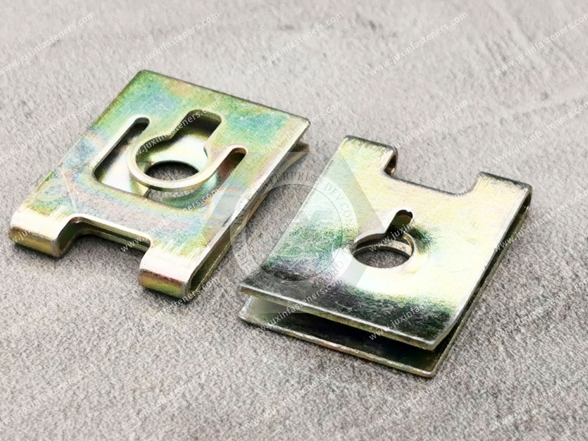
U-nuts and J-nuts should not automatically share the same panel layout.
A U-nut typically provides a more symmetrical clip body around the panel edge,
while a J-nut uses an offset geometry suited to applications where the hole centerline or access condition is not centered within a symmetrical clip profile.
The designer should evaluate:
Which clip leg carries the threaded feature
Installation direction
Available panel-edge access
Offset between the clearance hole and the clip body
Required anti-rotation behavior
Adjacent flange or obstruction
Driver-access direction
Whether the assembly requires a floating or fixed threaded position
For a detailed geometry comparison, see the related guide on U-Nuts vs J-Nuts.
The sheet-metal clearance hole must permit screw passage while maintaining sufficient surrounding material.
An oversized hole may improve assembly tolerance but can also:
Reduce the remaining edge ligament
Increase local panel deformation
Reduce bearing area
Expose the clip to uneven loading
Permit visible positional movement
Create sealing or appearance problems
An undersized hole may:
Interfere with the screw
Prevent engagement with the clip thread
Create false torque
Damage screw coatings
Generate metal debris
Encourage cross-threading during powered assembly
The hole diameter should be selected together with the screw diameter, screw tolerance, clip thread location, installation angle, driver repeatability, and required positional float.
For thread-selection considerations, see Screw Compatibility and Thread Engagement in Sheet-Metal Clip Nuts.
Punching can produce rollover, burnish, fracture, burrs, and local distortion.
When the hole is close to a panel edge, insufficient supporting material can increase deformation or create an incomplete hole profile.
Tool condition and punch-to-die clearance influence:
Hole size
Burr height
Edge breakout
Hole roundness
Local panel flatness
Positional repeatability
High-volume stamping can provide excellent repeatability, but tooling wear, strip positioning, material-feed variation, and die maintenance must be controlled.
The production control plan should monitor:
Hole position relative to the functional edge
Hole diameter
Edge condition
Burr height and direction
Flange width after forming
Bend angle
Clip fit and screw-entry alignment
Laser cutting removes mechanical punch loading but can produce heat-affected edges, taper, dross, or local hardness changes depending on the material and process.
Laser-cut prototypes should not automatically be treated as identical to stamped production parts.
A clip that fits a low-volume laser-cut prototype may behave differently after the component transfers to progressive stamping.
When holes are produced before bending, their final relationship to the flange edge and bend tangent depends on bend allowance, bend deduction, tooling radius, material thickness, grain direction, and springback.
Punching after forming may improve the functional relationship between the hole and the final flange edge, but tooling access and positional control may become more difficult.
The correct manufacturing sequence should be agreed upon during design-for-manufacturing review.
Burr direction can affect clip installation and seating.
A pronounced burr facing the clip entry direction may:
Increase installation force
Scratch the clip coating
Prevent full seating
Distort the spring legs
Create inconsistent throat-depth alignment
A burr around the screw-access hole may interfere with screw entry or concentrate stress near the hole.
Drawings and quality plans should define burr limits when burr condition affects fastener installation or joint performance.
Deburring requirements should also be compatible with coating, appearance, cleanliness, and production cost.
Clip-on nuts are often installed on zinc-plated, powder-coated, e-coated, painted, anodized, or otherwise finished panels.
Coatings influence hole and edge geometry by:
Increasing effective panel thickness
Reducing clearance at the clip throat
Filling part of the clearance hole
Creating friction during installation
Chipping at sharp panel edges
Changing grounding or electrical continuity
Affecting clip retention and removal force
The drawing and RFQ should state whether panel thickness is specified before or after coating and whether prototypes will represent the final production finish.
For thick powder coatings or multilayer finishes, the design team should avoid assuming that nominal bare-metal dimensions will remain functionally unchanged.
An insufficient hole setback can produce several failure modes.
The remaining ligament tears or permanently deforms during hole production, clip installation, or screw tightening.
The clip’s locating features may extend beyond the panel edge or fail to obtain full support.
The panel may no longer provide sufficient bearing area to resist clip movement under installation torque.
High local pressure can crack, chip, or scrape the finish at the panel edge.
The mating screw may contact the panel-hole edge before entering the clip thread.
A small ligament, rough punched edge, or distorted hole can create a local stress concentration under vibration and repeated service loading.
Excessive setback can be just as problematic.
The clip may:
Fail to reach the hole centerline
Stop before seating fully
Require excessive installation force
Deform as it is pushed beyond its intended throat depth
Sit under residual spring stress
Tilt the threaded feature
Disengage from the panel edge
Interfere with a nearby bend, rib, or component
Designers should not enlarge the clearance hole merely to compensate for an incorrect setback.
Excessive hole enlargement may conceal the alignment problem while reducing edge strength and assembly control.
Clip retention is the force that keeps the unloaded spring fastener attached to the panel before and during screw installation. It is not the same as the structural strength of the completed joint.
A clip can feel secure on the panel while its thread remains misaligned with the clearance hole.
When the screw is tightened through a misaligned panel:
The screw shank may bear against the panel.
The thread may enter at an angle.
The clip may shift or twist.
Installation torque may rise before clamp load develops.
The assembly tool may report a completed tightening cycle even though the joint is not correctly seated.
For this reason, retention force, thread alignment, strip torque, installation torque, and completed-joint performance should be evaluated separately.
For a deeper failure review, see Clip-On Nut Failure Analysis.
Panel thickness affects both clip fit and the structural stability of the hole-edge region.
Thin panels may be more susceptible to:
Edge curling
Local buckling
Hole elongation
Clip rocking
Coating damage
Permanent deformation under screw preload
Thicker panels may create other concerns:
Excessive clip installation force
Incomplete seating
Reduced spring travel
Spring-leg overstress
Incorrect throat-depth alignment if the fastener was designed for a thinner panel
Material properties also matter. Carbon steel, high-strength steel, stainless steel, and aluminum exhibit different stiffness, springback, hole-edge quality, galling behavior, and coating requirements.
Clip selection should therefore be based on the complete panel specification, not only on nominal sheet thickness.
See the related Clip-On Nut Panel Thickness Selection Guide for panel-range evaluation.
A robust CAD and drawing workflow should include the following steps.
Do not finalize the panel hole location using only a generic fastener name. Obtain the dimensional drawing for the intended part.
Identify the dimension from the clip entry edge to the threaded centerline.
Confirm hole diameter, shape, tolerance, screw access, and required positional float.
Use the maximum hole diameter and minimum setback when checking the worst-case ligament.
Confirm that the complete clip seating zone remains on a flat surface and does not ride on the bend radius.
Include panel-edge trimming, hole positioning, bending, clip dimensions, coating, and assembly variation.
Check clip installation direction, hand or tool clearance, screwdriver approach, and adjacent component interference.
Use the actual screw, panel, fastener, coating condition, and expected load direction.
Test representative sheet-metal parts made with production-intent material and manufacturing processes.
Identify which dimensions are critical to quality and include them in the supplier control plan.
A useful clip-on nut validation program should evaluate more than whether the clip can be pushed onto the panel.
Recommended checks include:
| Validation item | What it confirms |
|---|---|
| Clip installation force | The fastener can be installed without spring damage or panel distortion |
| Clip retention or pull-off force | The unloaded fastener remains attached during handling and screw rundown |
| Hole-to-thread alignment | The screw can enter without contacting the panel edge |
| Screw rundown test | The joint assembles without cross-threading, binding, or false torque |
| Tightening torque test | The fastener remains stable at the intended installation setting |
| Strip or failure torque | The assembly maintains an adequate margin above production torque |
| Push-out or displacement test | The clip does not migrate under axial installation loading |
| Repeated removal and reinstallation | Service-panel performance remains acceptable over the required maintenance cycle |
| Vibration testing | The fastener remains seated under the intended equipment environment |
| Corrosion exposure | The finish remains suitable for the specified environment |
| Dimensional capability study | Production hole setback and flange geometry remain statistically controlled |
Validation conditions should reflect production-intent panel material, thickness, coating, screw, clip, and assembly equipment.

Precision hole setback supports repeatable chassis and enclosure production while reducing manual adjustment and rework.
Typical applications include:
Modular enclosures
Equipment frames
Formed brackets
Machine covers
Access doors
Stamped subassemblies
Cabinet flanges are often narrow and formed near door seals, hinges, mounting rails, or folded edges. Hole placement must preserve clip seating while avoiding interference with gasket compression and electrical components.
Typical applications include:
Switchgear cabinets
Power distribution enclosures
Control boxes
UPS housings
Industrial electrical panels
Data-center power equipment
Machine guards and maintenance panels may be removed repeatedly. Correct hole alignment reduces thread damage and prevents maintenance technicians from forcing screws into misaligned clips.
Typical applications include:
CNC machine enclosures
Compressor guards
Conveyor access panels
Pump housings
Packaging machinery
Automated production equipment
Clip-on nuts may be used on serviceable brackets, shields, trim supports, electronics housings, and non-structural access panels.
Designs must consider vibration, coating, automated screw installation, and assembly takt time.
Air-handling units, fan housings, service covers, and filter panels often use folded sheet-metal flanges.
Correct setback supports field serviceability while helping the enclosure remain dimensionally stable.
Electrical cabinets and service panels in rolling stock require stable fastening under vibration, restricted access,
and repeated maintenance. Hole position, anti-rotation behavior, corrosion protection, and service-tool clearance should be reviewed together.
Compact control enclosures, sensor housings, AGV panels, and robot-controller covers often provide limited installation space.
A small hole-position error can prevent screw engagement where the driver approach is already constrained.
A production-ready drawing should identify:
Clip-on nut type or approved dimensional profile
Metric or inch thread designation
Thread pitch or series
Panel material
Nominal panel thickness
Panel-thickness tolerance
Final coating condition
Functional locating edge
Hole-center setback
Setback tolerance
Hole diameter and tolerance
Hole shape, where non-circular
Bend radius
Bend angle
Flange width
Burr limit and direction, where required
Screw installation direction
Required positional float
Installation torque
Minimum strip or failure torque, if specified
Retention-force requirement
Corrosion requirement
Inspection and sampling requirements
Annual volume and production location requirements
A vague note such as “clip nut to suit M6 screw” is insufficient for reliable OEM sourcing.
Purchasing teams may receive commercially attractive quotations that are not technically interchangeable.
Two clip-on nuts with the same thread size may differ in:
Throat depth
Overall width
Panel range
Thread position
Available float
Spring force
Entry geometry
Required hole diameter
Coating
Installation direction
Torque capacity
Substituting a lower-cost clip without checking these dimensions can require tooling changes, increase assembly defects, or create field-service problems.
A technically complete RFQ allows suppliers to quote the correct geometry and reduces the risk of post-award design changes.
When requesting an engineering review or quotation from JUXIN FASTENERS, provide the following information whenever available:
2D drawing in PDF format
3D model in STEP or another neutral CAD format
Panel assembly drawing
Hole setback and tolerance
Hole diameter and tolerance
Bend radius and flange geometry
Installation direction
Available assembly envelope
Material grade
Nominal thickness
Thickness tolerance
Mechanical condition or temper, where relevant
Coating or paint system
Final thickness after coating, if critical
Burr and edge requirements
U-nut, J-nut, barrel clip nut, or other spring-fastener type
Thread size and pitch
Metric or UNC/UNF thread system
Required panel range
Material preference
Surface finish
Corrosion requirement
Required retention force
Installation torque
Strip or failure torque target
Repeated-service requirement
Prototype quantity
Sample-test requirement
Initial production quantity
Estimated annual usage
Packaging requirements
Traceability requirements
Inspection documentation
Target production schedule
Delivery destination
For a new sheet-metal design, the lowest-risk process is to review the panel geometry and fastener profile before production tooling is finalized.
JUXIN FASTENERS can support OEM and industrial customers with:
Clip-on nut geometry selection
U-nut and J-nut comparison
Panel-thickness compatibility review
Hole setback and edge-ligament review
Bend-clearance evaluation
Metric and inch thread selection
Carbon steel and spring steel options
Surface-finish selection
Prototype and custom sample coordination
Drawing-based manufacturing evaluation
Production quotation and annual-volume planning
Where a standard clip geometry does not align with the intended panel layout, custom spring-fastener development may be evaluated using the customer’s drawings,
functional requirements, projected annual volume, and validation plan.
Start with the fastener’s functional throat depth from the clip entry edge to the thread centerline.
Use this as the nominal hole-center setback, then verify the remaining edge ligament, clearance-hole diameter, bend clearance, tolerance stack-up, coating condition, and available thread float.
No. The correct distance depends on clip geometry, throat depth, panel thickness, material, hole diameter, bend radius, manufacturing process, screw size, and loading condition.
International standards support drawing and verification methods but do not replace the selected product’s dimensional drawing.
The edge may deform, tear, bulge, or lose the support required to retain the clip. The screw may also contact the panel-hole edge and enter the clip thread at an angle.
The clip may not reach the hole, may fail to seat completely, or may be overstressed when forced beyond its intended throat depth.
Sometimes a controlled increase in clearance can provide additional screw access, but it should not be used to conceal an incorrect setback.
A larger hole reduces the remaining edge ligament and may weaken local panel support.
The controlling dimension should reflect the functional condition in which the clip is installed.
The drawing and process plan must account for bend allowance, springback, flange-width tolerance, and the manufacturing sequence.
The prototype may have been laser cut while production parts are punched and formed.
Differences in burrs, hole size, coating, bend position, material properties, and tooling tolerances can change final alignment.
Provide the panel drawing, material, thickness, coating, hole diameter, setback, bend radius, flange width, thread size, screw specification, target torque, sample quantity, and estimated annual demand.
Correct edge distance and hole setback engineering prevents avoidable failures before they reach the production line.
If your project requires U-nuts, J-nuts, clip-on nuts, barrel clip nuts, spring fasteners, or custom edge-mounted threaded components,
JUXIN FASTENERS can review the panel geometry and fastener interface before prototype or production release.
Send your 2D or 3D drawings, panel material, thickness, hole geometry, bend information, thread requirements, test expectations, prototype quantity, and projected annual volume to:
A complete technical package allows the engineering and sourcing teams to evaluate fit, alignment, manufacturability, testing requirements, and commercial feasibility more efficiently.
 MORE NEWS
Sep. 22, 2026
Sep. 22, 2026
Sep. 22, 2026
Contact Us
Tel.:
+86 020 8621 0320
+86 020 3121 6067
E-mail:
Technical Support:
Navigation
SEND INQUIREY