
Call Us
+86 136 6007 9809
Call Us
+86 136 6007 9809

Sep. 12, 2026
Modern automotive platforms rely on a combination of standard fasteners, customer-specific hardware, precision mechanical components, and application-specific parts.
While many joining requirements can be satisfied with standard screws, nuts, bolts, rivets, and clips, other components are defined by the vehicle architecture itself.
These may include precision shafts, pins, bushings, threaded adapters, mounting interfaces, spacers, brackets, sensor-related components, special fasteners, and other drawing-based mechanical parts.
For these components, CNC automotive part sourcing requires more than finding a machine shop and sending a CAD file.
The engineering team must define what actually matters functionally.
The procurement team must then ensure that the supplier can manufacture, inspect, document, and repeatedly supply the component according to those requirements.
A successful CNC sourcing process therefore connects:
Application → Drawing / CAD → Functional Dimensions → Material → Tolerance → Machining Route → Surface Treatment → Inspection → Quantity → RFQ → Production
JUXIN FASTENERS provides customer-specific CNC machining and fastening component solutions for automotive and industrial applications.
Current CNC capabilities described by JUXIN include CNC turning, Swiss-type machining, CNC milling, drilling,
tapping, threading, grooving, and turn-mill machining, depending on the component design and production requirements.
Customers can provide 2D drawings, 3D CAD files, samples, specifications, or inspection requirements.
This guide explains how automotive engineers, procurement managers, sourcing developers, and supply chain teams can prepare and evaluate a CNC machining RFQ more effectively.
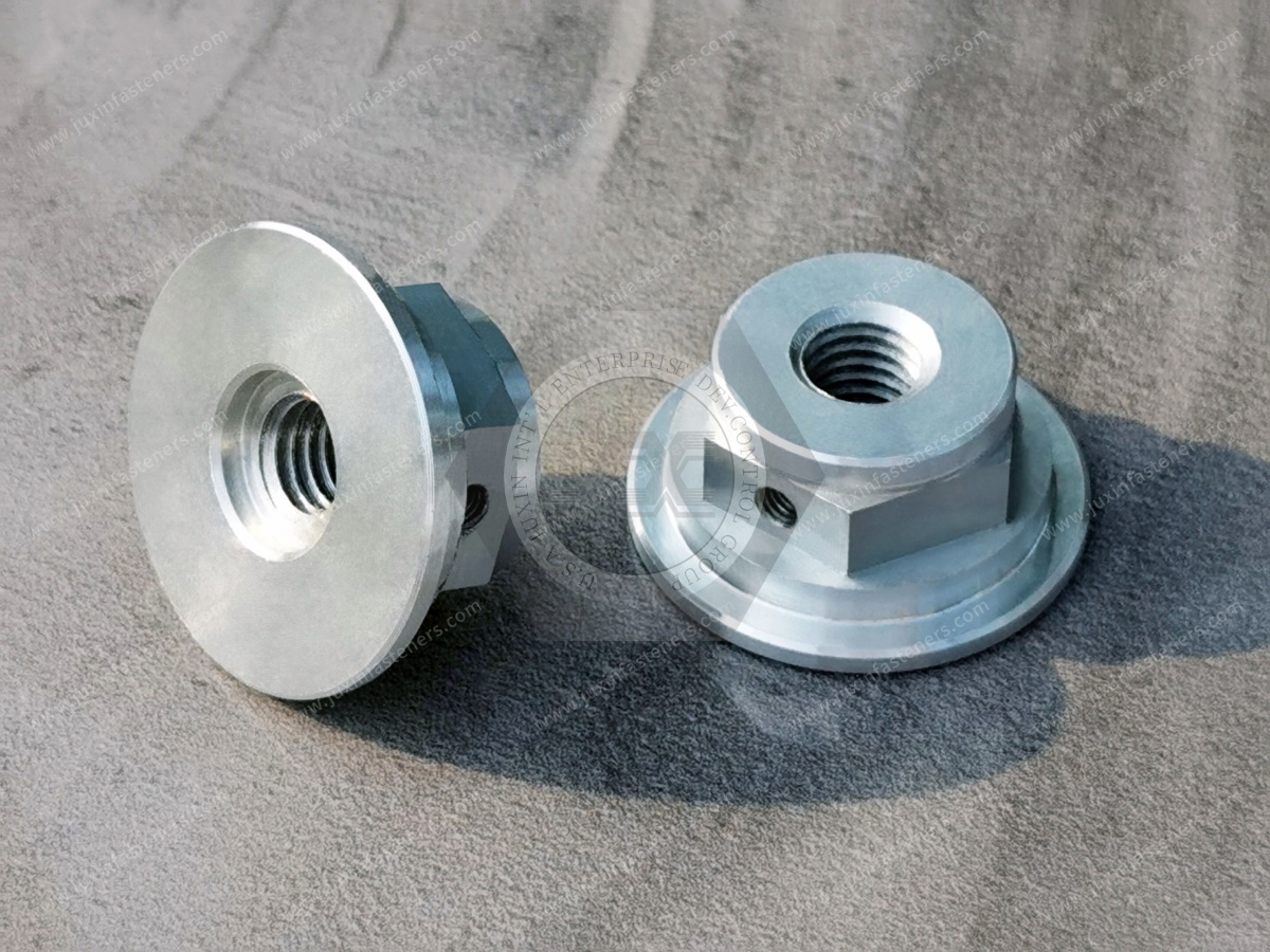
CNC automotive part sourcing is the engineering and procurement process of selecting a suitable machining supplier to
manufacture customer-specific automotive components according to defined drawings, CAD data, materials, tolerances, surface requirements, inspection criteria, and production quantities.
Unlike standard catalog purchasing, the supplier is manufacturing a component around the customer's engineering requirement.
Depending on the part, CNC machining may be used for:
Precision shafts
Pins
Bushings
Spacers
Threaded adapters
Mounting interfaces
Sensor-related components
Mechanical housings
Brackets
Custom screws and bolts
Special non-standard fasteners
Turned components
Milled components
Application-specific mechanical parts
The correct process depends on:
Part geometry
Material
Dimensional requirements
Tolerances
Surface requirements
Production quantity
Application
Inspection requirements
The important sourcing question is therefore not simply:
“Can this supplier CNC machine the part?”
It is:
“Can this supplier manufacture the functionally important features consistently using an appropriate process and inspection method?”
That distinction is the foundation of effective CNC automotive sourcing.
CNC machining provides flexibility when a component has geometry that is not well suited to a standard catalog part or when the required quantity and development stage make other production routes less appropriate.
Automotive development programs can require CNC components during:
Initial engineering development
Prototype development
Design validation
Pilot production
Low-volume production
Repeat production
Production of application-specific components
CNC machining can also remain appropriate for certain production components when the geometry, material, quantity, or dimensional requirements justify the process.
For example, a vehicle mechanism may require a custom shaft with several diameter sections, grooves, shoulders, or threads.
A different assembly may require a custom pin with a controlled interface between two moving components.
Another application may require a threaded adapter or mounting component with a customer-specific geometry.
JUXIN's current automotive CNC machining information identifies precision shafts, pins, bushings, threaded adapters, sensor components, connectors,
and mounting interfaces among typical CNC-machined automotive components.
An important sourcing principle is that CNC machining should not be selected simply because the component is “precision.”
For higher production volumes, cold forming, multi-stage forming, stamping, or other manufacturing processes may become more appropriate depending on the geometry.
For other components, CNC machining may remain suitable because of:
Complex geometry
Lower or medium production volume
Frequent engineering changes
Multiple diameter features
Custom threads
Special grooves
Functional interfaces
Prototype requirements
Therefore, the correct question is:
Which manufacturing route best matches the component's geometry, material, volume, tolerance, and production requirements?
This is also why supplier evaluation should include manufacturing-route competence, as discussed in the Custom Automotive Component Sourcing & Supplier Evaluation Protocol.

A CNC supplier cannot quote accurately if the engineering requirement is incomplete.
Before releasing an RFQ, engineering and procurement teams should review several specification areas.
The supplier needs to understand the actual component geometry.
This may include:
Overall length
Diameter
Step dimensions
Holes
Grooves
Threads
Chamfers
Radii
Shoulders
Slots
Pockets
Mounting surfaces
Functional interfaces
A 3D CAD model can communicate the general geometry, but the 2D drawing normally remains important for defining dimensions, tolerances, material, surface treatment, and other controlled requirements.
Not every dimension on a drawing has equal importance.
Some dimensions may determine:
Assembly fit
Bearing position
Shaft rotation
Thread engagement
Component location
Clearance
Alignment
Interchangeability
These should be distinguished from dimensions that have greater allowable variation.
This is one of the most important Information Gain points in CNC sourcing:
Do not make every dimension equally restrictive.
A practical drawing review should identify:
Function → Critical Feature → Required Tolerance → Inspection Method
rather than simply adding tight tolerances wherever greater precision appears desirable.
One of the most common problems in CNC sourcing is over-specification.
Engineers may tighten dimensions because they want predictable assembly performance. Procurement may then receive quotations with higher machining costs and longer production times.
The correct approach is not to make every dimension extremely tight.
Instead, determine which features actually control the function.
A functional tolerance may be required for:
A bearing or bushing interface
A shaft diameter
A mating hole
A locating diameter
A threaded interface
A sealing interface where applicable
A precision mounting surface
Other dimensions may not require the same degree of control.
Where the assembly permits greater variation, a more appropriate tolerance may help reduce unnecessary manufacturing complexity.
The final tolerance should always be determined by the engineering design and applicable drawing requirements.
CNC sourcing should also consider relationships between multiple dimensions.
For example:
Part A Dimension + Part B Dimension + Assembly Clearance → Functional Fit
A supplier may manufacture each individual dimension within tolerance while the assembled system still requires review of the overall tolerance stack.
This is particularly important for:
Shafts
Pins
Bushings
Sliding mechanisms
Pivot interfaces
Locating components
Multi-part mounting assemblies
Where a customer drawing uses geometric dimensioning and tolerancing (GD&T), the supplier should understand how the specified controls relate to the actual function.
Depending on the design, drawings may control:
Position
Flatness
Parallelism
Perpendicularity
Concentricity or related geometric relationships
Runout
Profile
Orientation
Location
The purpose is not simply to make the part “more precise.”
The purpose is to control the geometry that affects the assembly.
For procurement teams, this creates an important supplier evaluation question:
Can the supplier identify which geometric requirements affect function and explain how they will be inspected?
This is often more useful than asking only about the supplier's nominal machine accuracy.
Material should be specified clearly before quotation.
Depending on the component, automotive CNC parts may use:
Carbon steel
Alloy steel
Stainless steel
Aluminum alloys
Brass
Titanium
Engineering plastics
Other customer-specified materials
JUXIN's current CNC machining information lists stainless steel and other material categories across its CNC machining applications,
with material selection based on corrosion environment, strength, hardness, temperature, machinability, and customer specification.
“Stainless steel” may not be enough information.
The customer may need to define a particular grade according to:
Corrosion environment
Mechanical requirements
Temperature
Machinability
Surface condition
Application requirements
Likewise, “aluminum” may not sufficiently define the requirement when alloy or temper affects the component.
Where relevant, the drawing or specification may also define:
Heat treatment
Temper
Hardness
Stress-relieved condition
Other material condition requirements
These requirements should be clearly stated before the RFQ.
Depending on customer requirements, the sourcing package may request:
Material certificates
Material identification
Lot information
Certificates of conformity
Customer-specific material documentation
The supplier should confirm which documents can be provided before production rather than leaving the requirement until after delivery.
Threads are often treated as a simple dimension on a CNC drawing.
In practice, the thread can be a critical functional interface.
The drawing may define:
Thread diameter
Thread pitch
Internal or external thread
Thread standard
Thread class
Thread length
Thread engagement
End condition
Chamfer
Thread relief
Applicable thread requirements may reference international systems such as ISO, DIN, ASME/ANSI, SAE, or other customer-defined specifications.
The supplier should understand not only the nominal thread but also how the thread interacts with the mating component.
For example:
Thread → Mating Component → Engagement → Assembly Method → Functional Requirement
For threaded components receiving surface treatment, the sourcing team should also consider whether the specified treatment can influence the functional interface.
This should be evaluated according to the specific coating, dimensional requirement, and customer specification rather than assumed universally.
Surface requirements can affect both manufacturing and functional performance.
Depending on the application, requirements may include:
Surface roughness
Anodizing
Hard anodizing
Passivation
Zinc plating
Zinc-Nickel Alloy
Zinc-aluminum coatings
Electroless nickel
Functional or lubricating coatings
Other customer-specified treatments
The appropriate treatment depends on:
Base material
Corrosion exposure
Mating material
Assembly requirements
Dimensional requirements
Temperature
Functional surface requirements
This distinction is important.
Surface finish may describe the physical surface condition or roughness.
Surface treatment may describe a chemical, electrochemical, or coating process applied to the material.
A CNC RFQ should distinguish between the two when both matter.
Once the drawing has been reviewed, the supplier should determine which CNC process best matches the component.
CNC turning can be appropriate for rotational components such as:
Shafts
Pins
Bushings
Spacers
Threaded components
Stepped cylindrical parts
Adapters
CNC milling can be used for components with:
Flats
Slots
Pockets
Holes
Contoured surfaces
Non-rotational geometries
Multiple mounting features
Swiss-type machining can be considered for suitable small-diameter precision components requiring efficient processing of complex rotational features.
Drilling and tapping may be integrated into a broader machining process for components requiring:
Threaded holes
Mounting holes
Cross holes
Blind holes
Through holes
For components combining rotational and milled features, turn-mill processing can reduce the need for separate setups depending on the component geometry.
JUXIN's current automotive CNC information specifically identifies CNC turning, Swiss-type machining, CNC milling, drilling, tapping, threading, grooving,
and turn-mill machining as possible processes depending on design and production requirements.
A drawing may look straightforward in CAD but still present manufacturing challenges.
Before quotation, the supplier should consider:
Can the required internal feature actually be reached by the selected cutting tool?
Can the part be securely held without damaging functional surfaces?
How many machining setups are required?
Multiple setups can influence:
Cost
Lead time
Feature-to-feature relationships
Inspection requirements
Deep pockets, thin walls, long slender shafts, or difficult internal geometries may require additional process planning.
The supplier should identify these conditions during engineering review rather than discovering them during production.
Production quantity is one of the most important commercial variables in CNC sourcing.
A part may be suitable for CNC machining at one production volume but become commercially more attractive through another manufacturing route at a much higher volume.
CNC machining is often useful for:
Design verification
Prototype assemblies
Functional samples
Initial engineering evaluation
CNC can remain appropriate where:
Annual demand is limited
Geometry is complex
Engineering changes are expected
Dedicated high-volume tooling is difficult to justify
Once the component is validated, repeat CNC production can benefit from:
Established machining programs
Defined tooling
Controlled workholding
Stable inspection methods
Established material sourcing
Repeat production procedures
At higher volumes, procurement should compare CNC machining with other possible manufacturing routes.
Depending on geometry and material, alternatives may include:
Cold forming
Multi-stage forming
Stamping
Other specialized production methods
The correct decision is therefore:
Geometry + Material + Tolerance + Quantity + Production Stability
rather than:
“CNC is more precise, so CNC must be better.”
An effective RFQ should provide enough information for suppliers to quote the same technical requirement.
A practical CNC automotive RFQ package can include the following.
Include:
Dimensions
Tolerances
GD&T where applicable
Material
Surface requirements
Thread specifications
Drawing revision
Where available, provide a suitable CAD format such as:
STEP
IGES
Native CAD format where appropriate
The CAD model helps the supplier understand the geometry and prepare machining processes.
Define:
Material grade
Alloy
Temper or heat-treatment condition where applicable
Material documentation requirements
Specify:
Treatment type
Required appearance where relevant
Functional requirements
Dimensional considerations
Documentation requirements where applicable
Identify features that are functionally important.
This can help the supplier determine:
Machining sequence
Inspection method
Measurement frequency
Process controls
Specify:
Thread size
Pitch
Thread standard
Thread class
Engagement length
Fit requirements
Provide:
Prototype quantity
Sample quantity
Pilot quantity where applicable
Order quantity
Annual forecast where available
Specify whether the project requires:
Dimensional inspection
Material documentation
Functional inspection
Surface-finish verification
Hardness testing
Customer-defined inspection reports
Certificates of conformity
Define where applicable:
Quantity per package
Individual protection
Lot identification
Labels
Barcodes
Inner packaging
Outer packaging
Include:
Prototype target date
Sample approval timing
Production release date
Required delivery schedule
Expected order frequency
One of the most practical ways to improve an RFQ is to classify requirements.
Instead of sending a drawing with dozens of dimensions and expecting every supplier to interpret them identically, the customer can identify:
These directly influence:
Assembly
Movement
Alignment
Sealing where applicable
Thread engagement
Location
Functional performance
These require defined tolerances but may not require the same inspection intensity.
These can follow the applicable general tolerances unless otherwise specified.
This creates a clearer connection:
Function → Dimension → Tolerance → Process → Inspection
It also gives procurement a better basis for comparing supplier quotations.
If Supplier A quotes a very tight tolerance across every dimension while Supplier B identifies only the functionally critical dimensions, the quotations are not necessarily based on the same manufacturing interpretation.
The sourcing team should therefore compare the technical assumptions before comparing unit prices.
Inspection should not be designed independently from engineering requirements.
A useful inspection plan connects each requirement with a verification method.
| Requirement | Example Feature | Possible Verification Approach |
|---|---|---|
| Dimensional | Diameter / length | Appropriate dimensional measurement |
| Thread | Internal or external thread | Thread gauge or dimensional verification |
| Position | Hole location | Appropriate dimensional or coordinate measurement |
| Surface | Surface roughness | Suitable surface measurement method |
| Material | Specified alloy | Material documentation or verification as required |
| Hardness | Heat-treated component | Hardness testing where specified |
| Function | Mating interface | Functional gauge or assembly verification where applicable |
| Appearance | Surface treatment | Visual or customer-defined inspection |
The exact inspection method should depend on the drawing, tolerance, feature, and customer quality requirements.
JUXIN's current automotive CNC information states that inspection may include dimensional measurement, thread inspection, hole diameter and position checks,
surface-finish verification, material verification, hardness testing, and functional inspection depending on customer requirements.
CNC sourcing becomes much more efficient when engineering and procurement recognize that they are evaluating the same component from different perspectives.
Functional geometry
Tolerances
Material
Thread
Mating interface
Surface condition
Assembly
Prototype validation
Inspection
Unit cost
Quantity
Lead time
MOQ
Tooling
Production scalability
Packaging
Commercial terms
Supplier responsiveness
Production continuity
Capacity
Delivery
Inventory
Packaging
Logistics
Change management
Long-term supplier stability
The best RFQ connects these three perspectives before the quotation is requested.
CNC-machined components are not limited to one vehicle subsystem.
Potential CNC components include:
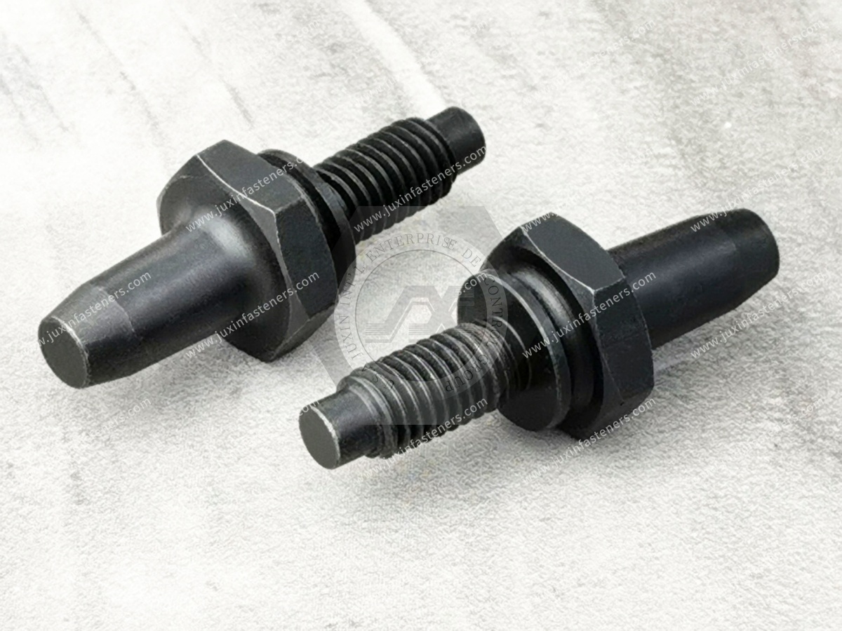
Pins
Shafts
Bushings
Spacers
Mounting interfaces
Application-specific mechanical components
These may work alongside rivet nuts, custom aluminum components, bolts, and other fastening hardware.
For the broader application, see Automotive Chassis & Undercarriage Fastening.
CNC-machined components may include:
Shift shafts
Shift pins
Pivot shafts
Rolling shafts
Rocker pivot shafts
Sliding columns
Ball pins
The important requirements may involve rotational interfaces, dimensional relationships, movement, and assembly geometry.
See Automotive Shift Systems: Fastening Engineering, Precision Shafts & OEM Sourcing Guide.
Sunroof and panoramic roof mechanisms may require:
Pivot shafts
Pins
Guide components
Mechanical interfaces
Application-specific components
The correct design depends on the movement type and mating geometry.
See Automotive Sunroof Systems: Fastening Engineering, Precision Shafts & OEM Sourcing Guide.
Automotive wiper systems may use:
Stainless steel solid rivets
Stainless steel shoulder rivets
Step rivets
Precision linkage components
Application-specific shafts or pins
See Automotive Wiper System Fastening Solutions.
Seat assemblies can include:
Pins
Pivot components
Mounting components
Shafts
Custom mechanical hardware
The appropriate component depends on whether the part belongs to the structural mounting system, adjustment mechanism, pivot interface, or trim system.
See Automotive Seat Systems: Fastening Engineering, High-Strength Hardware & OEM Sourcing Guide.
CNC-machined components may also complement application-specific spoiler fastening hardware.
For example:
Rear Spoiler Assembly → Mounting Interface → Nylon Rear Spoiler Clip + Automotive Spoiler Slide Bolt + Application-Specific Components
The confirmed JUXIN Spoiler Slide Bolt family includes M5 and M6 configurations, with representative M6 × 14 and M6 × 20 examples.
Applicable configurations may use property classes 8.8 or 10.9 and finishes including Color Zinc, Zinc-Nickel Alloy, and Black Zinc.
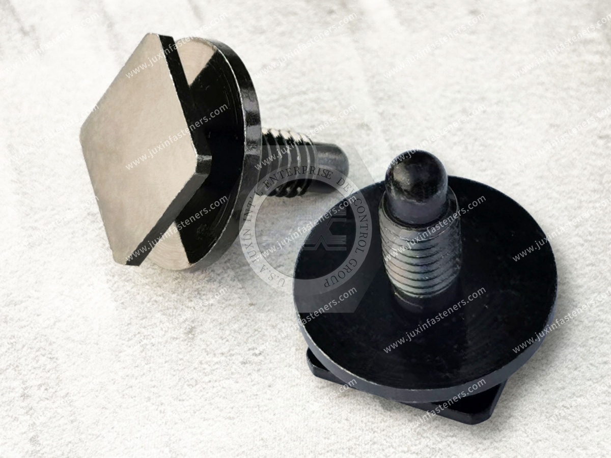
The special head geometry engages a mounting slot, track, or channel, with the practical installation sequence:
Slide → Position → Engage → Tighten
The anti-rotation effect depends on the actual mating geometry.
For the complete application, see Automotive Rear Spoiler Fastening Components.
For the metal component specifically, see Automotive Spoiler Slide Bolts.
CNC machining is one part of a broader automotive manufacturing and fastening system.
Depending on the program, JUXIN FASTENERS can also supply:
Custom screws
Custom bolts
High-strength fasteners
Rivets
Rivet nuts
Weld nuts
Self-clinching fasteners
Plastic clips
Nylon retainers
Threaded inserts
Washers
Pins
Shafts
Stamped components
Application-specific mechanical components
The automotive industry page on JUXIN's current website describes a broader manufacturing scope covering cold forging, multi-stage forming,
CNC machining, stamping, injection molding, and custom mechanical components for customer drawings and specifications.
This broader manufacturing structure matters when an OEM wants to evaluate multiple component families rather than source every part through unrelated suppliers.
A 3D model communicates geometry but may not define all tolerances, materials, finishes, or functional requirements.
Unnecessary tolerances can increase machining complexity without improving the actual assembly.
“Steel,” “stainless,” or “aluminum” may not provide enough information.
Heat treatment, temper, hardness, or other conditions may affect the finished component where specified.
The finished part should be evaluated as:
Machined Geometry + Surface Treatment + Final Functional Dimension
rather than considering machining and finishing as completely separate processes.
Two suppliers may quote different manufacturing assumptions.
The lower price is not necessarily lower if it is based on a different tolerance interpretation, material, inspection scope, or production quantity.
A supplier cannot evaluate production economics effectively if it receives only “please quote” without knowing whether the requirement is:
10 prototypes
500 pieces
10,000 pieces
100,000 pieces
Repeat annual production
Producing one accurate sample is different from maintaining dimensional consistency across repeat production.
The supplier should be evaluated on both stages.
Before selecting a CNC automotive parts supplier, procurement teams can ask:
Can the supplier review 2D drawings and 3D CAD?
Can the supplier identify critical dimensions?
Can the supplier evaluate manufacturability?
Can the supplier clarify ambiguous requirements?
Can the supplier recommend an appropriate machining route?
Can the supplier support turning?
Can the supplier support milling?
Can the supplier support drilling and tapping?
Can the supplier support threading and grooving?
Can the supplier support turn-mill components?
Can the supplier support the required production volume?
How are critical dimensions inspected?
How are threads verified?
How are materials controlled?
How are surface treatments verified?
What inspection documentation can be supplied?
Can the supplier support prototype and repeat production?
How are machining programs controlled?
How are production changes managed?
How are batches identified?
Is the quotation based on the correct drawing revision?
Are material and finish included?
Are inspection requirements included?
Are packaging requirements included?
Is lead time clearly stated?
Is the quotation quantity-based?
A professional CNC sourcing workflow can be structured as:
Engineering Drawing / CAD
↓
Application and Mating Interface Review
↓
Material Review
↓
Critical Dimension Identification
↓
Tolerance Review
↓
Machining Route Evaluation
↓
Surface Treatment Review
↓
Inspection Planning
↓
RFQ
↓
Prototype / Sample
↓
Dimensional and Functional Inspection
↓
Customer Approval
↓
Production
↓
Final Inspection
↓
Repeat OEM Supply
This structure gives engineering, procurement, quality, and supply chain teams a common reference point.
JUXIN FASTENERS provides customer-specific CNC machining and fastening component solutions for automotive and other engineering-driven industries.
Current JUXIN automotive CNC information identifies applications including precision shafts, pins, bushings, threaded adapters, sensor components,
connectors, and mounting interfaces. Production can be evaluated for prototypes, low-volume production, repeat OEM orders, and mass production depending on material,
geometry, tolerance, quantity, and application requirements.
The broader automotive manufacturing scope also includes:
CNC machining
Cold forging
Multi-stage forming
Stamping
Injection molding
Custom mechanical components
Fasteners
Plastic components
Weld fasteners
Threaded inserts
Rivet nuts
Application-specific components
For a CNC project, JUXIN FASTENERS can review customer-provided:
2D drawings
3D CAD files
Samples
Material requirements
Surface-treatment requirements
Dimensional requirements
Inspection criteria
Production quantities
The manufacturing route is then evaluated according to the actual component rather than forcing every project into the same process.
Before sending a CNC automotive RFQ, confirm that the package includes:
Engineering
2D drawing
3D CAD
Drawing revision
Critical dimensions
GD&T where applicable
Thread specifications
Mating interface information
Material
Material grade
Temper or heat-treatment condition where applicable
Material documentation requirements
Surface
Surface finish
Surface treatment
Coating or plating requirements
Functional surface requirements where applicable
Production
Prototype quantity
Production quantity
Annual forecast
Target production date
Repeat-order expectations
Quality
Inspection requirements
Critical-to-function characteristics
Material documentation
Functional testing where applicable
Customer-specific quality documents
Logistics
Packaging
Labeling
Lot identification
Delivery location
Delivery schedule
The more clearly these requirements are defined, the easier it becomes for engineering and procurement teams to compare supplier quotations on the same basis.
CNC automotive part sourcing is the engineering and procurement process of selecting a suitable machining supplier to manufacture
customer-specific automotive components according to drawings, CAD data, materials, tolerances, surface requirements, inspection criteria, and production quantities.
A complete RFQ should normally include 2D drawings, 3D CAD data, drawing revision, material, tolerances, critical dimensions, thread requirements,
surface treatment, inspection requirements, quantities, packaging, and delivery requirements.
Tolerance review helps distinguish functionally critical dimensions from general dimensions.
This can help avoid unnecessary manufacturing complexity while preserving the dimensional requirements needed for assembly.
Depending on the component, CNC turning, milling, Swiss-type machining, drilling, tapping, threading, grooving, and turn-mill machining may be considered.
It can be suitable for certain production components, depending on geometry, material, tolerance, quantity, and production economics.
At higher volumes, other processes such as cold forming or stamping may also need to be evaluated.
Depending on the application and customer specification, CNC components may use carbon steel, alloy steel, stainless steel, aluminum alloys, brass, titanium, engineering plastics, and other suitable materials.
Production quantity affects process selection, machining economics, tooling, production planning, and lead time.
A process suitable for prototypes may not be the most economical option for high-volume production.
Compare suppliers against the same technical baseline, including material, drawing revision, critical dimensions, tolerances, surface treatment,
inspection requirements, quantity, packaging, and delivery schedule. Unit price should be evaluated together with technical and supply assumptions.
JUXIN FASTENERS provides customer-specific CNC machining and fastening component solutions based on drawings, CAD files, samples, material requirements,
surface treatments, inspection criteria, and production requirements. Depending on the project, CNC turning, Swiss-type machining, milling, drilling, tapping, threading, grooving, and turn-mill machining may be evaluated.
The most effective CNC sourcing process starts before the quotation.
It starts by defining what the component actually needs to do.
A professional sourcing workflow connects:
Application → Mating Interface → Drawing / CAD → Critical Dimensions → Material → Tolerance → Machining Route → Surface Treatment → Inspection → Quantity → RFQ → Production
Whether the requirement is a precision shaft, pin, bushing, threaded adapter, mounting interface, custom fastener, or other drawing-based automotive component,
JUXIN FASTENERS can evaluate the requirement according to the customer's engineering and production specifications.
For a CNC automotive component inquiry, please provide your 2D drawing, 3D CAD file or sample, together with the material, critical tolerances, surface treatment,
quantity, application information, inspection requirements, and target delivery schedule where available.
JUXIN FASTENERS
Email: info@juxinfasteners.com
Website: www.juxinfasteners.com
 MORE NEWS
Sep. 14, 2026
Sep. 13, 2026
Contact Us
Tel.:
+86 020 8621 0320
+86 020 3121 6067
E-mail:
Technical Support:
Navigation
SEND INQUIREY