
Call Us
+86 136 6007 9809
Call Us
+86 136 6007 9809

Jun. 02, 2026
Electrical grounding and bonding in railway equipment cannot be reduced to selecting a conductive bolt or grounding stud.
A reliable electrical connection is a system consisting of the fastener, conductor, contact surfaces, parent structure, surface treatment,
clamp load, installation process and environmental protection.
This distinction is critical in rolling stock, railway electrical cabinets, auxiliary power equipment, battery equipment, signaling assemblies,
control systems and other rail electrical applications where mechanical and electrical requirements interact.
The correct engineering path is:
Electrical Function → Fault / Bonding Requirement → Parent Material → Contact Interface → Fastener Technology → Clamp Load
→ Surface Condition → Corrosion Protection → Vibration → Installation → Electrical Validation → Lifecycle Inspection
JUXIN FASTENERS supports selected railway and industrial electrical equipment programs with grounding studs, weld studs,
threaded studs, machine screws, bolts, nuts, washers, rivet nuts, self-clinching fasteners, stainless steel fasteners,
zinc-nickel coated fasteners and custom drawing-based fastening components.
The most important engineering principle is:
Mechanical Fastening ≠ Electrical Bonding.
A mechanically secure connection is not automatically a qualified electrical connection.
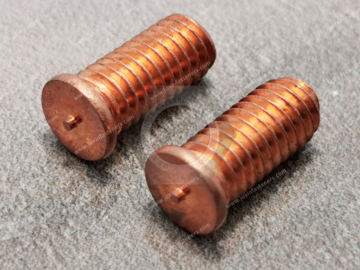
Electrical bonding fasteners are mechanical components used as part of a connection intended to establish or maintain electrical continuity between conductive components.
Depending on the railway equipment architecture, these may include:
Grounding studs
Weld studs
Threaded studs
Grounding bolts
Bonding screws
Nuts
Lock nuts
Flat washers
Contact washers where specified
Self-clinching studs
Welded grounding points
Custom electrical fastening components
The fastener provides mechanical retention and contact pressure.
The complete electrical performance depends on the assembled interface.
The terms grounding and bonding are often used together, but engineers should identify the actual electrical function.
Bonding generally establishes electrical continuity between conductive components so that they remain at controlled electrical potential relative to each other.
Grounding or earthing connects part of the electrical system to the designated grounding or protective network according to the applicable system architecture.
The terminology and technical requirements depend on the railway equipment and applicable electrical specification.
For fastener selection, the important point is:
Fastener Name ≠ Electrical Function.
A product called a “grounding stud” does not by itself define the electrical performance of the installed connection.
Potential applications can include:
Rolling-stock electrical cabinets
Auxiliary power equipment
Traction-related equipment enclosures
Battery equipment
Control cabinets
Signal equipment
Communication equipment
HVAC electrical assemblies
Metallic enclosures
Equipment frames
Cable-lug connections
Protective bonding networks
Selected carbody bonding interfaces
Different locations can have fundamentally different electrical requirements.
| Application | Mechanical Requirement | Electrical Requirement | Key Engineering Risk |
|---|---|---|---|
| Electrical cabinet | Secure removable connection | Protective bonding | Coating at contact interface |
| Grounding lug | Stable clamp force | Low, stable contact resistance | Loosening / corrosion |
| Welded grounding stud | Strong attachment | Electrical continuity | Weld quality / surface condition |
| Aluminum enclosure | Thread and bearing integrity | Bonding path | Galvanic corrosion |
| Stainless enclosure | Mechanical retention | Bonding | Passive oxide / interface design |
| Vibration-sensitive equipment | Clamp retention | Stable continuity | Joint movement |
| Outdoor equipment | Corrosion resistance | Long-term electrical continuity | Moisture / chloride / coating |
| EMC-related interface | Mechanical continuity | Defined bonding performance | Interface impedance / geometry |
This table is a starting framework rather than a universal railway specification.
Consider a typical grounding connection:
Metal Structure → Grounding Stud → Contact Surface → Cable Lug → Washer → Nut
The final performance depends on every interface.
This leads to another critical principle:
Conductive Fastener ≠ Conductive Joint.
A highly conductive component cannot compensate for a poorly prepared or unstable contact interface.
Engineers sometimes focus first on the bulk electrical conductivity of the fastener material.
But in a mechanical bonding connection, electrical performance can be strongly influenced by the interfaces between components.
Factors can include:
Surface oxides
Paint
Powder coating
Plating
Contamination
Contact pressure
Surface roughness
Corrosion
Joint movement
Therefore:
Low Bulk Material Resistance ≠ Automatically Low Contact Resistance.
This is one of the most important considerations when selecting grounding hardware.
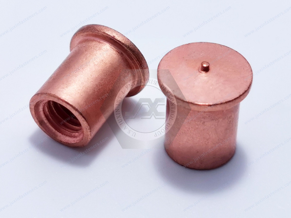
Mechanical clamp force helps maintain contact between conductive surfaces.
Insufficient clamp force can allow:
Micro-movement
interface contamination
fretting
increased contact resistance
But:
More Tightening Torque ≠ Automatically Better Electrical Connection.
Excessive tightening can damage:
Threads
Cable lugs
washers
thin sheet
aluminum structures
The joint requires controlled clamp load rather than maximum torque.
Torque is an installation input.
Preload is the tensile force developed in the fastener and the corresponding clamp force created across the joint.
The relationship depends heavily on friction.
Therefore:
Same Torque + Different Friction ≠ Same Preload.
This matters when changing:
Coating
lubricant
washer
nut
surface finish
in an electrical bonding assembly.
Grounding studs can provide dedicated threaded attachment points for electrical bonding connections.
Possible configurations include:
Weld studs
Threaded studs
Flanged studs
Custom drawing-based grounding studs
depending on the parent structure and equipment design.
But:
Grounding Stud ≠ Qualified Grounding System.
The stud is only one component of the electrical path.
Weld studs can create permanent attachment points on suitable metallic structures.
Their performance depends on:
Stud material
Parent material
Weld geometry
welding process
surface condition
alignment
Therefore:
Strong Stud ≠ Strong Welded Grounding Point.
And:
Mechanical Weld Strength ≠ Electrical Bonding Performance.
Both mechanical and electrical characteristics may require validation.
Depending on the welding technology and project requirements, process variables can include:
Current
Time
Stud geometry
Parent material
Surface condition
Alignment
Tooling
A correctly manufactured stud can still perform poorly if the installation process is uncontrolled.
Excessive welding energy can cause:
Distortion
expulsion
damage to parent material
inconsistent weld formation
A validated process window is required.
Threaded studs can provide removable electrical connections for:
Cable lugs
bonding straps
grounding conductors
The thread should provide reliable mechanical assembly.
However:
Correct Thread ≠ Correct Electrical Connection.
Electrical performance remains dependent on the contact interface.
Machine screws or bolts can be used as part of electrical bonding connections where the assembly is designed accordingly.
The engineering requirements may include:
Thread engagement
clamp force
bearing surface
coating
contact interface
locking strategy
corrosion
A standard bolt should not automatically be marketed as an electrical bonding fastener merely because it is metallic.
Steel, stainless steel, copper alloys and other conductive materials can all conduct electricity.
That does not mean every fastener made from those materials is suitable for every railway grounding application.
Electrical suitability depends on the complete system.
Washers can perform several different functions:
Load distribution
Surface protection
Locking-system interface
Contact-interface function where specifically designed
But:
Washer ≠ Automatic Electrical Contact Improvement.
A conventional flat washer should not be assumed to improve conductivity simply because it increases apparent surface area.
Certain washer or contact geometries may be designed to penetrate surface films or coatings and create controlled metal-to-metal contact.
However, this creates a trade-off.
A serrated contact feature can disturb protective coatings and expose the substrate.
Therefore:
Better Initial Electrical Contact ≠ Better Long-Term Corrosion Protection.
The complete interface must be engineered for both functions.
Aggressive teeth can:
Damage coatings
mark aluminum
create local corrosion sites
change bearing behavior
The correct geometry depends on the system design.
Railway equipment often requires corrosion protection.
Electrical bonding often requires conductive contact.
These objectives can conflict.
For example:
Structure → Protective Coating → Contact Interface → Cable Lug
A continuous nonconductive coating at the required bonding interface can interfere with electrical continuity.
Therefore:
Best Corrosion Coating ≠ Best Electrical Contact Surface.
Specifying:
Zinc
Zinc-nickel
Tin
Other metallic coating
does not by itself define contact resistance.
Electrical behavior depends on:
Coating thickness
Topcoat
passivation
contact pressure
surface condition
mating material
environment
For mechanical sourcing, the specification may also need to define:
Coating thickness
Corrosion requirement
Friction
topcoat
appearance
where applicable.
Zinc-nickel coatings may be considered for selected steel fasteners where corrosion resistance and mechanical requirements support their use.
But:
Zinc-Nickel Coating ≠ Automatic Grounding Qualification.
If the fastener participates directly in the current path, the complete contact interface should be electrically validated.
Stainless steel may offer useful corrosion resistance for selected railway electrical applications.
Common industrial stainless families can include A2/304-type and A4/316-type materials depending on the applicable fastener standard and environment.
But:
Stainless Steel ≠ Corrosion-Proof.
And:
Stainless Steel ≠ Automatically Best Electrical Bonding Material.
Material selection must consider both mechanical and electrical functions.
Stainless steel obtains corrosion resistance partly through its passive surface behavior.
This means engineers should not assume that bulk conductivity alone defines the quality of an electrical contact.
Again:
Conductive Material ≠ Qualified Electrical Interface.
A4/316-type stainless can offer improved corrosion resistance in certain chloride-containing environments.
But selection also depends on:
Electrical function
mating material
mechanical properties
galling risk
cost
environment
Aluminum structures introduce additional considerations.
These include:
Surface oxide
relatively soft parent material
thread strength
galvanic interaction
contact-interface preparation
If the aluminum parent thread or bearing surface becomes the limiting element, increasing bolt strength does not solve the problem.
Possible engineering approaches can include:
Increased thread engagement
Threaded inserts
Rivet nuts
Alternative attachment architecture
depending on the design.
Electrical bonding assemblies may combine:
Steel
Stainless steel
Aluminum
Copper-containing conductors
in the same connection.
In the presence of an electrolyte, dissimilar-metal combinations can create galvanic-corrosion concerns.
Therefore:
Corrosion-Resistant Fastener ≠ Corrosion-Resistant Electrical Assembly.
The complete material couple and environment must be evaluated.
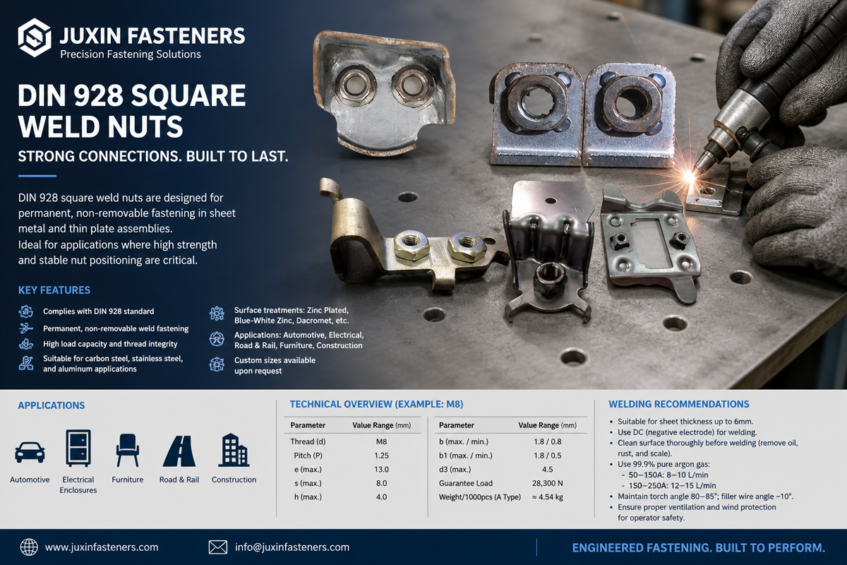
Copper and copper-containing conductor components may provide useful electrical conductivity.
But coupling them directly with aluminum or other metals can create corrosion concerns depending on the environment and interface.
Therefore:
Higher Conductivity ≠ Automatically Better Material Combination.
Railway equipment can experience dynamic loading.
Joint movement can affect both:
Mechanical integrity
Electrical contact stability
However:
Vibration ≠ Automatic Fastener Loosening.
Self-loosening depends on joint mechanics.
Clamp load can decrease because of:
Settlement
Embedment
Creep
thermal effects
parent-material deformation
without fastener rotation.
Electrical bonding reliability can still be affected because contact pressure changes.
Lock nuts or locking washers may help address rotational loosening in suitable applications.
But they do not automatically guarantee electrical performance.
Therefore:
Anti-Loosening Performance ≠ Electrical Bonding Performance.
Both functions should be specified separately.
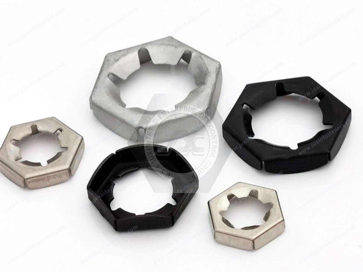
All-metal or polymer-insert lock nuts can provide rotational resistance.
That resistance is not the clamp force across the electrical interface.
A washer should be selected according to its actual function.
Flat washers, contact washers, spring elements and wedge-locking systems perform different roles.
Railway electrical equipment can experience temperature changes during:
Operation
shutdown
environmental cycling
Different materials expand and contract at different rates.
This can influence:
Contact pressure
interface movement
preload
Therefore:
Room-Temperature Contact Resistance ≠ Full-Service Electrical Reliability.
Environmental exposure can create corrosion products at the contact interface.
These may affect electrical performance over time.
A connection that passes an initial resistance measurement may therefore require environmental validation for the intended application.
Long-term performance can depend on:
Moisture
Chlorides
temperature cycling
vibration
corrosion
clamp-force retention
Salt-spray testing can support comparative corrosion evaluation.
It cannot directly predict the number of years a bonding connection will survive in service.
Some railway assemblies use bonding connections as part of broader electromagnetic compatibility strategies.
However:
Metal-to-Metal Contact ≠ Automatically Qualified EMC Bond.
High-frequency bonding behavior can depend on more than simple DC resistance.
Relevant system considerations can include:
Bond geometry
path length
contact area
interface condition
frequency
These requirements belong to the electrical and EMC design of the equipment.
A connection with low DC resistance does not automatically provide the required behavior across all frequencies.
This distinction is important for:
Communication equipment
Control electronics
converter equipment
shielding assemblies
Grounding and bonding connections may contribute to protective electrical functions.
But:
Fastener ≠ Electrical Safety System.
The complete electrical architecture must be designed and validated according to the applicable project requirements.
Railway projects can reference multiple international standards depending on equipment and application.
A fastener supplier should distinguish:
Fastener Requirement → Joint Requirement → Equipment Requirement → System Requirement
These are not interchangeable.
EN 50153 addresses protective provisions relating to electrical hazards for railway rolling stock within its scope.
Its requirements can influence electrical bonding and protective connection design.
However:
EN 50153 ≠ Generic Grounding Stud Certification.
A grounding stud does not become independently “EN 50153 certified” simply because it is used in an equipment assembly designed to meet applicable requirements.
EN 50155 addresses electronic equipment used on rolling stock within its scope.
It should not be presented as a generic product standard for grounding studs.
EN 61373 can be relevant to shock and vibration testing of railway equipment within its scope.
But:
Equipment-Level Vibration Requirement ≠ Generic Grounding Fastener Certification.
The installed equipment configuration matters.
IEC, EN, OEM and railway-operator requirements may define electrical safety, bonding, EMC or equipment requirements depending on the system.
The applicable standard set should therefore be identified from the actual project.
A bolt or nut may comply with an ISO or DIN dimensional or mechanical-property standard.
That does not establish electrical bonding performance.
A useful engineering framework is:
Failure Mode → Requirement → Test → Acceptance Criteria
Potential failure mechanisms include:
Excessive contact resistance
Loss of clamp force
Fastener rotation
corrosion
weld failure
thread failure
cable-lug movement
surface degradation
Depending on the application, validation may include:
Dimensional inspection
Material verification
Mechanical-property testing
Thread inspection
Coating thickness
Torque-tension evaluation
Prevailing-torque testing
Weld validation
Contact-resistance measurement
Environmental conditioning
Corrosion testing
Vibration / shock testing
Thermal cycling
Assembly-level electrical testing
Not every application requires every test.
Testing should address the real failure modes.
A useful electrical test must define:
Measurement points
assembly configuration
surface condition
clamp condition
environmental state
acceptance limit
Without these parameters, a resistance value can be difficult to interpret.
A new assembly may show acceptable contact resistance but degrade after:
Vibration
corrosion
thermal cycling
repeated maintenance
where applicable.
Some protective bonding paths may need to withstand defined fault-current conditions.
But the requirement depends on the electrical system.
Therefore:
Grounding Stud Size ≠ Automatic Fault-Current Rating.
And:
Material Conductivity ≠ Short-Circuit Qualification.
Where fault-current capability is relevant, the complete current path and thermal/mechanical effects should be validated to the project requirement.
A technically useful RFQ should define:
Fastener geometry
Material
Mechanical properties
coating
parent material
conductor
electrical function
contact-resistance requirement
installation
environment
validation
This gives both engineering and procurement a measurable specification.
Supplier development should evaluate more than dimensions.
A practical framework is:
Controlled Drawing + Revision + Material + Mechanical Properties + Thread + Critical Geometry + Surface Treatment
+ Friction + Installation Behavior + Electrical Interface Requirement + Functional Testing + Documentation + Change Control
A grounding stud can match every dimension on its drawing while the final connection has unacceptable resistance because:
Paint remains on the contact surface
Clamp force is insufficient
corrosion develops
lug installation is incorrect
Therefore:
Dimensional Conformance ≠ Electrical Bonding Performance.
A raw-material certificate can verify important material information.
It does not validate:
Finished geometry
coating
weld
installation
electrical interface
Traceability helps identify:
Material batch
Production lot
Process history
but it does not prove application performance.
Railway OEMs and equipment manufacturers may develop alternative suppliers for:
Supply continuity
Lead-time reduction
cost control
regional sourcing
But:
Same Dimensions ≠ Functional Equivalence.
For grounding hardware, second-source qualification may need to compare:
Drawing / revision
Material
Mechanical properties
Thread
Critical geometry
Surface treatment
coating thickness
friction
contact-interface behavior
installation
weldability where applicable
electrical validation
Two parts described as stainless steel or zinc-nickel plated can still behave differently because of:
Grade
Surface condition
coating
geometry
manufacturing
installation
This is particularly important when the coating participates in or affects the electrical interface.
Changing washer geometry can affect:
Contact pressure
surface penetration
coating damage
electrical performance
Changing from a standard nut to a prevailing-torque nut can alter:
Installation torque
preload
reuse behavior
Therefore substitutions should be reviewed as part of the complete connection.
Depending on geometry and volume, grounding components can use:
Cold heading
Thread rolling
CNC machining
Stamping
Secondary machining
Welding-related installation processes
Surface treatment
The manufacturing route should follow the design.
A CNC-machined component may be suitable for complex geometry or lower-volume custom requirements.
Cold forming can be more suitable for other high-volume components.
Electrical reliability depends heavily on interface design and assembly.
Unnecessarily tight dimensional tolerances can increase cost without improving electrical performance.
Electrical, mechanical and railway equipment engineers searching for railway grounding fasteners may be asking:
What fasteners are used for railway electrical bonding?
How should a grounding stud be attached?
What material should a railway grounding stud use?
Can stainless steel be used for grounding?
How do coatings affect electrical bonding?
How do I ground an aluminum railway enclosure?
What causes grounding contact resistance to increase?
How should railway bonding connections be tested?
How does vibration affect grounding connections?
How should a grounding fastener second source be qualified?
These are system-engineering questions, not merely product-selection questions.
Commercial searches can include:
Railway grounding fastener manufacturer
Railway grounding stud supplier
Electrical bonding fastener supplier
Weld grounding stud manufacturer
Railway electrical fastener supplier
Custom grounding stud manufacturer
Railway bonding hardware supplier
OEM grounding fasteners
Second-source grounding stud supplier
Procurement should convert these searches into measurable engineering RFQs.
Define:
Protective bonding
Equipment grounding
EMC bonding
Other project-specific function
Define:
Welded stud
Threaded stud
Bolt
Screw
Self-clinching stud
Other attachment
Specify:
Carbon steel
Stainless steel
Aluminum
Other alloy
Specify:
Cable lug
Bonding strap
Washer system
Direct component-to-component contact
Define:
Bare metal
Plated
Painted
Powder coated
Anodized
Other treatment
Define:
Thread
Material
Mechanical properties
clamp requirement
tightening method
locking requirement
Define:
Contact resistance
Current requirement where applicable
Fault-current requirement where applicable
EMC requirement where applicable
Specify:
Temperature
Humidity
Condensation
Chlorides
industrial contaminants
vibration / shock
Define:
Mechanical tests
Electrical tests
Environmental tests
Assembly-level acceptance criteria
When an existing electrical bonding joint has a problem, the failure mode should be identified before changing the fastener.
| Observed Problem | Possible Engineering Cause |
|---|---|
| High contact resistance | Surface film, coating, contamination, low contact pressure |
| Resistance increases over time | Corrosion, relaxation, interface movement |
| Nut rotates loose | Preload / joint movement / locking issue |
| Clamp force decreases without rotation | Settlement, embedment, thermal effects |
| Grounding stud detaches | Weld or parent-material failure |
| Thread strips | Parent material, engagement, overload |
| Aluminum corrosion | Galvanic interaction / environment |
| Cable lug moves | Clamp / installation / interface issue |
| Coating damaged | Serration / installation / environment |
| Passes mechanical test but fails electrical test | Contact-interface problem |
The objective is to identify whether the problem originates from:
Fastener → Installation → Contact Interface → Surface Treatment → Parent Material → Environment → Electrical Architecture
A grounding joint can be mechanically intact while its electrical resistance becomes unacceptable.
Conversely, it can show acceptable electrical resistance during an initial test while the mechanical connection is not sufficiently stable for long-term service.
Therefore:
Mechanical Validation ≠ Electrical Validation.
Both may be required.
Procurement should evaluate:
Total Installed Cost = Fastener + Surface Preparation + Installation + Tooling + Electrical Testing + Inspection + Rework + Maintenance + Downtime + Logistics + Supply Risk
A slightly cheaper grounding stud can become more expensive if it requires:
Additional surface preparation
difficult installation
excessive inspection
frequent maintenance
This page should serve as the dedicated Railway Electrical Bonding Fasteners & Grounding Connection Engineering resource.
Recommended internal links include:
Railway Grounding Studs → dedicated grounding-stud product and application guide
Railway Electrical Equipment Fasteners → cabinets, power supplies and electrical equipment
Railway Signal Equipment Fasteners → trackside signal lights and control enclosures
Railway Fasteners → rolling-stock application hub
Railway Fastener Engineering → vibration, preload and bolted-joint design
Railway Anti-Loosening Fasteners → locking technology selection
Railway Bolt Loosening → preload-loss and failure analysis
Railway Fastener Installation → tightening and preload control
Stainless Steel Fasteners → corrosion-resistant fastener selection
Fastener Surface Treatment & Coating Selection → coating, friction and corrosion
Zinc-Nickel Coated Fasteners → Zn-Ni coating engineering
Fasteners for Aluminum → aluminum parent-material joint design
Custom Fastener Manufacturing → drawing-based components and DFM
Fastener Quality Control → supplier qualification and traceability
Use the existing indexed JUXIN FASTENERS URL when implementing these internal links.
They are fasteners used as part of electrical grounding or bonding connections in railway equipment. They can include grounding studs,
weld studs, bolts, screws, nuts, washers and custom bonding components.
No. Electrical performance depends on the complete connection, including the stud, contact surface, conductor, washer, nut, clamp load, coating and environment.
Possibly in an appropriately engineered system, but metallic conductivity alone does not qualify a bolt for a grounding application.
It can be suitable for selected applications, but corrosion resistance, electrical-interface behavior, mating materials and mechanical requirements must all be considered.
No. A4/316-type stainless can provide improved corrosion resistance in some environments, but it is not automatically the best electrical or mechanical solution.
Not automatically. Washer function depends on its geometry, material, surface treatment and the contact-interface design.
Certain designed contact geometries can penetrate surface films or coatings, but this may also damage corrosion protection. The complete interface must be validated.
Not necessarily, but the coating and complete contact interface must be evaluated against the electrical requirement.
No. Mechanical strength, corrosion, galvanic compatibility, installation and interface behavior also matter.
Possible causes include corrosion, loss of contact pressure, contamination, thermal cycling and interface movement.
Not necessarily. Excessive tightening can damage the fastener, conductor or parent structure. The goal is controlled clamp force.
No. Torque is an installation input; preload and clamp force depend strongly on friction and joint conditions.
Dynamic loading can contribute to joint movement or clamp-force changes, but vibration does not automatically cause bolt self-loosening.
No. High-frequency bonding behavior can depend on geometry, path length and interface characteristics in addition to DC resistance.
No. EN 50153 concerns electrical protective provisions for railway rolling stock within its scope. It should not be represented as a generic product certification for an individual grounding stud.
No. It concerns railway equipment shock and vibration within its scope. An individual fastener should not automatically be described as EN 61373 certified.
JUXIN FASTENERS can support selected drawing-based grounding studs, weld studs, threaded components and associated fasteners according to geometry,
material, surface treatment, mechanical requirements, electrical-interface requirements and production volume.
The weak sourcing approach is:
Need Grounding → Buy Conductive Stud → Tighten It → Assume Low Resistance
The stronger engineering approach is:
Electrical Function → Current / Bonding Requirement → Parent Material → Contact Interface → Fastener Technology → Surface Treatment → Clamp Load
→ Corrosion → Vibration → Installation → Electrical Validation → Lifecycle Control
The key principles are:
Mechanical Fastening ≠ Electrical Bonding
Fastener Name ≠ Electrical Function
Conductive Fastener ≠ Conductive Joint
Low Bulk Material Resistance ≠ Automatically Low Contact Resistance
More Tightening Torque ≠ Automatically Better Electrical Connection
Torque ≠ Preload
Same Torque + Different Friction ≠ Same Preload
Grounding Stud ≠ Qualified Grounding System
Strong Stud ≠ Strong Welded Grounding Point
Mechanical Weld Strength ≠ Electrical Bonding Performance
More Welding Energy ≠ Better Grounding Stud Installation
Correct Thread ≠ Correct Electrical Connection
Conductive Material ≠ Qualified Electrical Connection
Washer ≠ Automatic Electrical Contact Improvement
Better Initial Electrical Contact ≠ Better Long-Term Corrosion Protection
More Aggressive Serration ≠ Better Bonding Connection
Best Corrosion Coating ≠ Best Electrical Contact Surface
Coating Name ≠ Electrical Performance
Coating Name ≠ Complete Coating Specification
Zinc-Nickel Coating ≠ Automatic Grounding Qualification
Stainless Steel ≠ Corrosion-Proof
Stainless Steel ≠ Automatically Best Electrical Bonding Material
316 ≠ Automatically Better Grounding Fastener
Stronger Steel Fastener ≠ Stronger Aluminum Joint
Corrosion-Resistant Fastener ≠ Corrosion-Resistant Electrical Assembly
Higher Conductivity ≠ Automatically Better Material Combination
Vibration ≠ Automatic Fastener Loosening
Preload Loss ≠ Self-Loosening
Locking Feature ≠ Electrical Reliability
Anti-Loosening Performance ≠ Electrical Bonding Performance
Prevailing Torque ≠ Preload
Washer ≠ Automatic Anti-Loosening Device
Room-Temperature Contact Resistance ≠ Full-Service Electrical Reliability
Initial Low Resistance ≠ Long-Term Low Resistance
Salt Spray Hours ≠ Railway Service Life
Metal-to-Metal Contact ≠ Automatically Qualified EMC Bond
DC Bonding Performance ≠ High-Frequency EMC Performance
Fastener ≠ Electrical Safety System
EN 50153 ≠ Generic Grounding Stud Certification
Equipment-Level Vibration Requirement ≠ Generic Grounding Fastener Certification
Product Standard ≠ Electrical-System Qualification
More Testing ≠ Better Engineering
One Resistance Measurement ≠ Lifecycle Validation
Grounding Stud Size ≠ Automatic Fault-Current Rating
Material Conductivity ≠ Short-Circuit Qualification
Drawing Compliance ≠ Electrical Qualification
Dimensional Conformance ≠ Electrical Bonding Performance
Material Certificate ≠ Finished Grounding Connection Qualification
Traceability ≠ Qualification
Same Dimensions ≠ Functional Equivalence
Same Material Name ≠ Same Finished Grounding Performance
Coating Substitution Can Be an Engineering Change
Washer Substitution Can Be an Engineering Change
Nut Substitution Can Be an Engineering Change
CNC ≠ Automatically Better Grounding Stud
Tighter Tolerance ≠ Better Electrical Bonding
Mechanical Validation ≠ Electrical Validation
For electrical engineers, the objective is to create a stable electrical path under the real mechanical and environmental conditions of the railway equipment.
For mechanical and structural engineers, the objective is to maintain the contact pressure and physical integrity required by that electrical interface.
For procurement and supplier-development teams, the objective is to source not merely a “conductive stud,” but a controlled component whose material,
geometry, coating, installation behavior and functional requirements match the approved electrical bonding design.
JUXIN FASTENERS supports selected railway electrical and grounding applications with:
Grounding studs
Weld studs
Threaded studs
Machine screws
Bolts
Standard nuts
Lock nuts
Washers
Rivet nuts
Self-clinching fasteners
Stainless steel fasteners
Zinc-nickel coated fasteners
Custom drawing-based grounding components
Cold-formed components
CNC precision components
OEM / ODM fastener development
Second-source fastener development
For a railway electrical bonding fastener RFQ, provide:
2D Drawing + 3D Model + Part / Revision + Railway Application + Electrical Function + Parent Material + Conductor / Cable Lug + Contact Interface
+ Fastener Type + Material + Mechanical Properties + Thread + Surface Treatment + Coating Thickness + Friction Requirement
+ Tightening Method + Target Preload Where Applicable + Locking Requirement + Contact Resistance Requirement
+ Current / Fault Requirement Where Applicable + Vibration / Shock Requirement + Temperature + Corrosion Environment
+ Environmental Validation + Electrical Validation + Traceability Requirement + Prototype Quantity + Annual Volume
For safety-related or project-controlled electrical bonding locations, also provide the applicable OEM / railway-project specification, approved drawing,
installation procedure and validation requirements.
JUXIN FASTENERS
Railway Grounding Fasteners | Electrical Bonding Fasteners | Grounding Studs | Weld Studs | Custom Electrical Fasteners
Email: info@juxinfasteners.com
Website: www.juxinfasteners.com
Contact Us
Tel.:
+86 020 8621 0320
+86 020 3121 6067
E-mail:
Technical Support:
Navigation
SEND INQUIREY



