
Call Us
+86 136 6007 9809
Call Us
+86 136 6007 9809

Sep. 30, 2026
Blind rivets provide a practical permanent fastening method when an assembly can be accessed from only one side.
They are widely used in commercial vehicles, rail equipment, industrial machinery, HVAC systems, electrical enclosures,
appliance assemblies, sheet-metal structures, and other applications where installing a conventional bolt and nut would require inaccessible rear-side access.
However, “blind rivet” describes a broad family of fasteners.
A standard open-end blind rivet, multi-grip rivet, and structural blind rivet can differ substantially in body deformation, mandrel behavior, grip capability,
load performance, hole-filling characteristics, and installation requirements.
For engineers, the correct question is therefore not simply:
“What diameter blind rivet should I use?”
It is:
“Which rivet architecture matches the joint stack, hole condition, load direction, substrate material, installation access, environment, and production process?”
For procurement and supplier-development teams, another question is equally important:
“Which characteristics must remain equivalent when an existing blind rivet is cross-referenced or second-sourced?”
JUXIN FASTENERS supplies industrial blind-riveting products including Self Plugger Steel Blind Rivets, structural blind rivets,
open-end blind rivets, multi-grip blind rivets, countersunk blind rivets, and related fastening components for OEM and production sourcing requirements.
A blind rivet is a permanent mechanical fastener designed for installation when access is available from only one side of the joint.
A typical break-mandrel blind rivet consists of:
a tubular rivet body;
a manufactured head;
a mandrel extending through the rivet body;
a mandrel head that participates in setting the rivet.
During installation, the rivet is inserted through a prepared hole and a riveting tool pulls the mandrel while reacting against the manufactured rivet head.
This action deforms the rivet body on the blind side of the assembly and draws the joint members together.
When the designed installation sequence is completed, the mandrel breaks at or near its intended break region.
The exact deformation and mandrel behavior depend on the rivet design.
This distinction becomes particularly important when comparing standard blind rivets with structural blind rivets.
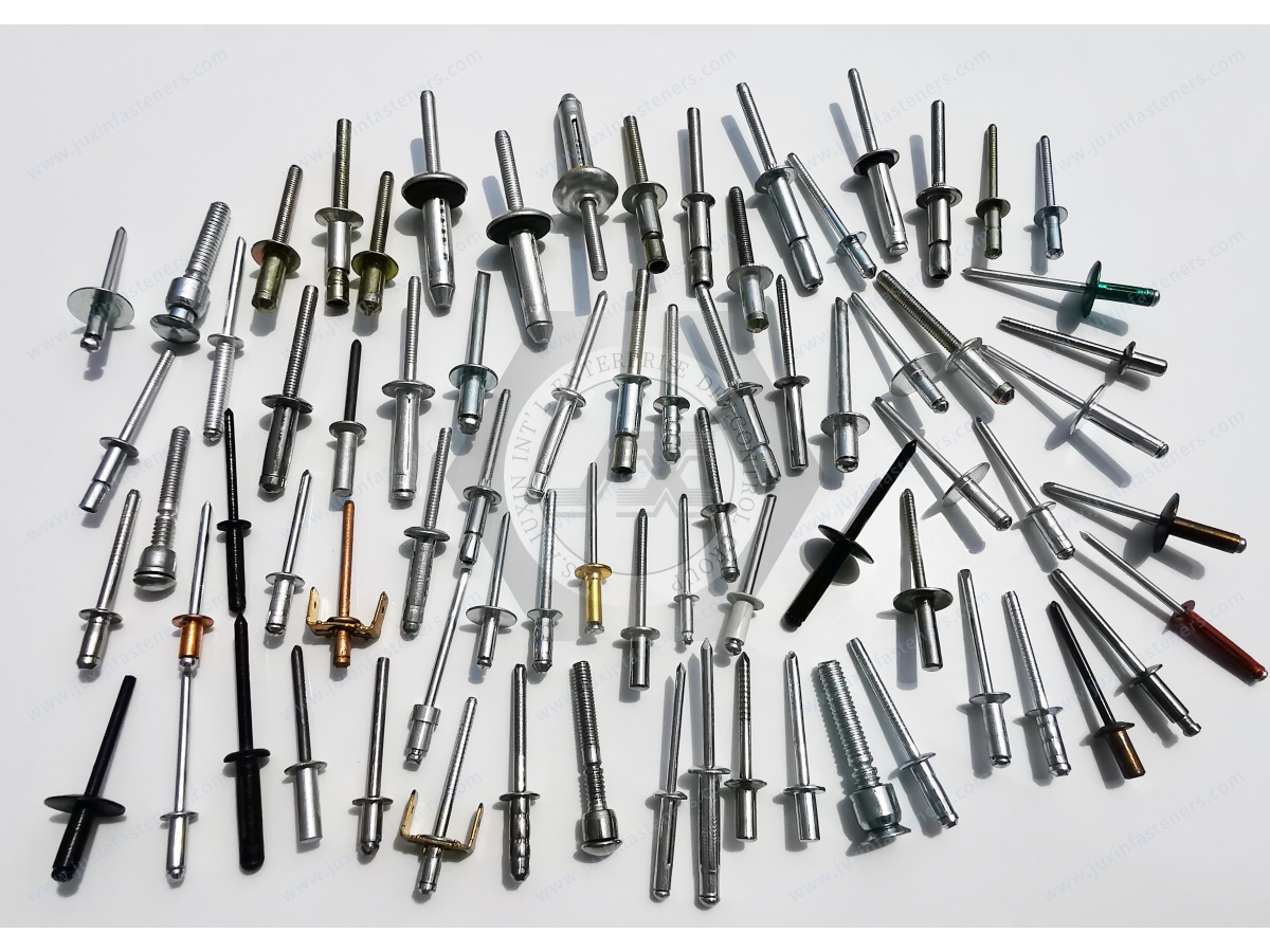
Understanding the installation sequence helps engineers diagnose poor joints and specify replacement rivets correctly.
The rivet body passes through aligned holes in the materials being joined.
Hole diameter and condition influence installation, alignment, joint movement, and final rivet behavior.
The installation tool grips and pulls the mandrel while its nosepiece reacts against the rivet head.
As the mandrel moves, the rivet body deforms on the inaccessible side of the assembly.
Depending on the rivet design, this may create a blind-side head, bulb, expanded region, or other controlled deformation.
The deformation draws the joined materials together.
The ability of the rivet to properly take up the joint depends strongly on whether the total material stack lies within the intended grip range.
After the required deformation is developed, the mandrel breaks.
In some standard blind rivets, the remaining mandrel portion primarily reflects the setting process.
In structural blind rivets, retained-mandrel behavior may be deliberately engineered as part of the installed fastener system.
This is one reason a standard blind rivet and structural blind rivet should not be treated as equivalent products.
The term “structural blind rivet” should not simply be used as a marketing synonym for a stronger pop rivet.
Structural blind rivets are designed for applications requiring higher and more controlled installed-joint performance than typical general-purpose blind riveting.
| Engineering Factor | General-Purpose Blind Rivet | Structural Blind Rivet |
|---|---|---|
| Primary use | General sheet-metal fastening | More demanding structural or high-load joints |
| Mandrel role | Primarily installation mechanism | May remain mechanically integrated with installed rivet |
| Hole filling | Product dependent | Often an important design characteristic |
| Load capability | Product-specific general assembly | Designed for higher application-specific performance |
| Grip behavior | Defined by individual rivet | May incorporate wider or specialized grip behavior |
| Installation equipment | Standard blind-rivet tooling depending on size | Tooling must match structural rivet design |
| Qualification | Dimensional and application requirements | Often requires closer functional validation |
Actual performance must always be based on the specific rivet design and validated product data rather than on the category name alone.
Self-plugger steel blind rivets are relevant to industrial applications requiring blind-side installation with a steel rivet construction and controlled installed behavior.
For engineers searching specifically for self plugger blind rivets, the product name alone is not sufficient to determine interchangeability.
The important sourcing and engineering characteristics can include:
rivet body diameter;
body length;
manufactured-head geometry;
grip range;
hole requirement;
rivet-body material;
mandrel material;
installed blind-side geometry;
mandrel behavior;
installation-tool compatibility;
mechanical performance requirements.
When an existing self-plugger rivet is being replaced or second-sourced, these interface and functional characteristics should be compared before approving an alternative.
Grip range describes the total joint thickness over which a particular rivet is intended to install correctly.
This is not necessarily the thickness of one panel.
For a two-sheet joint:
Total Grip = Thickness of Sheet A + Thickness of Sheet B
For a multi-layer assembly, the complete material stack must be considered.
This distinction is important because drawings and RFQs sometimes specify only individual panel thickness while omitting the total installed stack.
If the actual joint thickness falls outside the rivet's intended range on the low side, the rivet may not deform in the intended manner for that application.
Potential consequences depend on the rivet design but may include:
excessive deformation;
undesirable blind-side geometry;
poor joint take-up;
installation inconsistency.
If the joint stack exceeds the rivet's specified grip capability, the rivet may not develop the intended blind-side formation or joint condition.
Potential consequences can include:
incomplete setting;
inadequate joint take-up;
abnormal mandrel break behavior;
reduced functional performance.
The correct engineering approach is therefore to match the actual stack-up to the manufacturer's specified grip range rather than selecting body length by appearance.
Multi-grip blind rivets are designed to accommodate a wider range of material thicknesses than a conventional narrow-grip rivet.
This can be useful in production environments where several assemblies have similar hole and load requirements but different material stacks.
Potential sourcing and manufacturing benefits include:
fewer rivet part numbers;
simplified line-side inventory;
reduced risk of selecting the wrong grip-specific SKU;
greater flexibility across related assemblies.
However, SKU reduction should not override engineering requirements.
The selected multi-grip rivet must still satisfy:
hole requirements;
substrate compatibility;
installed geometry;
load requirements;
head-style requirements;
environmental requirements;
tooling compatibility.
Blind rivet performance is closely related to the prepared hole.
An oversized or damaged hole can change how the rivet body interacts with the joint.
A hole that is too small can prevent insertion or damage coatings during assembly.
Engineers should therefore control more than nominal rivet diameter.
Relevant hole characteristics can include:
diameter;
tolerance;
roundness;
alignment between layers;
burr condition;
edge quality;
surface coating;
distance from the panel edge.
For automated riveting, hole consistency becomes even more important because equipment has less ability than a human operator to compensate for poor alignment.
A common specification mistake is treating grip range and hole diameter as interchangeable fit parameters.
They control different interfaces.
Grip range controls the axial material stack.
Hole diameter controls the radial rivet-to-panel interface.
A rivet can have the correct grip range and still perform poorly if the hole is unsuitable.
Likewise, a correctly sized hole does not compensate for a rivet selected outside its intended grip range.
Both must be controlled.
Blind rivets may experience different combinations of load depending on the assembly.
Shear loading acts primarily across the rivet axis and attempts to slide the joined materials relative to each other.
The resulting joint performance depends not only on rivet strength but also on:
hole fit;
number of rivets;
rivet spacing;
edge distance;
substrate strength;
sheet thickness;
load distribution.
Tensile loading tends to separate the joint members along the rivet axis.
Relevant factors include:
rivet-head geometry;
blind-side formation;
substrate thickness;
substrate strength;
local bearing area;
rivet design.
For thin or soft sheet material, the surrounding panel can become the limiting element before the rivet itself reaches its nominal mechanical capacity.
This is why selecting a rivet solely from a published rivet strength value can be misleading.
The complete joint must be evaluated.
This is an important consideration in lightweight industrial assemblies.
Increasing rivet diameter or selecting a higher-strength structural blind rivet does not automatically increase usable joint strength if the surrounding sheet cannot support the transferred load.
Possible substrate-related failure modes include:
hole elongation;
edge tear-out;
local bearing deformation;
pull-through;
sheet distortion;
cracking around the hole.
Engineers should therefore evaluate the rivet and substrate as one mechanical system.
Blind rivets are available in different combinations of rivet-body and mandrel materials.
Selection may involve:
steel;
stainless steel;
aluminum alloys;
other application-specific material combinations.
Material selection affects more than nominal rivet strength.
Engineers should consider:
parent-panel material;
corrosion environment;
moisture exposure;
temperature;
coating system;
required mechanical performance;
galvanic interaction between dissimilar metals.
For example, installing a steel rivet into an aluminum assembly may require evaluation of galvanic-corrosion risk when the joint is exposed to moisture or other conductive environments.
A material combination should not be described as universally corrosion-safe merely because one component has a protective coating.
The complete material and environmental system must be considered.
Blind rivet head geometry affects both packaging and load distribution.
Common configurations can include standard dome heads, large-flange heads, and countersunk heads.
A general-purpose configuration suitable for many sheet-metal assemblies.
A larger bearing area may be useful when fastening softer or thinner materials where load distribution is important.
A countersunk blind rivet can provide a more flush surface where assembly geometry requires it.
However, countersinking removes material from the parent sheet.
In thin sheet, engineers should verify that sufficient material remains around the hole and that the joint geometry can support the intended load.
Flush appearance should not override structural requirements.
Both products solve one-sided-access problems, but they serve different assembly strategies.
A blind rivet normally creates a permanent riveted joint.
A rivet nut creates a reusable female thread in a panel so that a screw or bolt can later be installed and removed.
Use a blind rivet when the assembly is intended to remain permanently joined and riveting suits the load and service requirements.
Consider a rivet nut when:
future disassembly is required;
a removable panel is needed;
service access is expected;
a reusable threaded attachment point is required.
This distinction is important for engineers searching broadly for “blind fastening solutions.”
Blind riveting can be integrated into repetitive production operations, but automation changes the importance of dimensional consistency.
Production engineers may need to evaluate:
rivet feeding;
orientation;
insertion;
hole alignment;
tool access;
nosepiece compatibility;
mandrel extraction;
setting-force behavior;
cycle time;
process monitoring.
A rivet that works during occasional manual installation may require additional validation before use in automated production.
For second-source development, automation compatibility can therefore be part of functional equivalence.
Blind rivets can be used in sheet-metal panels, brackets, body structures, equipment housings, and other assemblies where backside access is limited.
Structural blind rivets may be considered where the application requires higher joint performance than a general-purpose rivet can provide.
Rail equipment can include interior panels, lighting assemblies, equipment housings, partitions, brackets, and other components with restricted installation access.
The selected fastener must still be evaluated against the applicable mechanical, fire, vibration, environmental, and project requirements.
HVAC housings, duct-related components, equipment cabinets, brackets, and sheet-metal structures commonly benefit from rapid one-sided assembly.
Rivet selection should reflect material thickness, corrosion environment, vibration, and service requirements.
Blind rivets can create permanent enclosure and bracket connections without requiring access for a rear nut.
Where enclosure sealing is required, the sealing strategy should be evaluated separately. A conventional open-end blind rivet should not automatically be assumed to create a leak-tight penetration.
Guards, covers, housings, sheet-metal frames, and auxiliary assemblies can use blind riveting where permanent assembly and one-sided installation are appropriate.
Two rivets with the same nominal diameter and overall length may have different grip ranges, body constructions, head styles, mandrel systems, and installed performance.
Grip range should be compared with total assembled thickness rather than one individual sheet.
The surrounding panel, hole, edge distance, and load distribution may govern joint failure.
For structural rivets, mandrel retention or locking can be part of the installed mechanical system.
Different rivet designs may require different nosepieces, pulling capacity, stroke, or dedicated tooling.
Open-end blind rivets should not automatically be considered watertight or airtight. Sealing requirements need separate engineering evaluation.
Procurement teams frequently search for alternative sources based on an existing part number, drawing, or physical sample.
For blind rivets, a useful principle is:
Visual Similarity ≠ Dimensional Equivalence ≠ Installation Equivalence ≠ Functional Equivalence
Compare relevant characteristics such as:
body diameter;
body length;
grip range;
head diameter;
head height;
mandrel geometry;
required hole diameter.
Confirm both:
rivet-body material;
mandrel material.
Where specified, also confirm coating and other surface requirements.
Verify:
setting-tool compatibility;
nosepiece requirements;
pulling behavior;
mandrel break behavior;
installed blind-side geometry.
Depending on the application, qualification may require evaluation of:
shear performance;
tensile performance;
mandrel retention;
hole filling;
joint take-up;
vibration behavior;
corrosion requirements;
installed appearance;
production consistency.
A dimensional match alone does not establish structural equivalence.
If procurement already has an existing self-plugger or structural blind rivet and needs a second source, start with the existing technical information.
Useful inputs include:
existing manufacturer part number;
customer part number;
2D drawing;
physical sample;
body and mandrel materials;
grip range;
hole specification;
mechanical requirements;
installation-tool information;
annual usage.
A physical sample is useful for dimensional cross-reference, but it cannot independently reveal every material, coating, heat-treatment, or functional requirement.
Where original specifications are available, they should be supplied together with the sample.
For technical review and quotation, provide as much of the following information as applicable:
existing or reference part number;
2D drawing;
3D CAD model where relevant;
physical sample for cross-reference projects;
rivet type;
rivet-body diameter;
required grip range;
total joint stack thickness;
hole diameter and tolerance;
head style;
rivet-body material;
mandrel material;
parent-panel materials;
coating or corrosion requirements;
shear and tensile requirements where specified;
mandrel-retention requirements where applicable;
installation-tool requirements;
manual or automated assembly method;
environmental requirements;
inspection or documentation requirements;
sample quantity;
production quantity;
estimated annual usage.
JUXIN FASTENERS can use this information to evaluate the appropriate blind-rivet family, dimensional requirements,
material combination, cross-reference feasibility, sample requirements, and production sourcing route.
Blind riveting is most effective when the rivet is selected as part of the complete joint rather than as an isolated catalog component.
The engineering sequence should be:
Access Condition → Joint Stack → Hole Interface → Substrate Material → Load Direction → Rivet Architecture → Installation Process → Environmental Requirements → Validation
The procurement sequence should then continue:
Existing Specification or Drawing → Dimensional Cross-Reference → Material Review → Sample Evaluation → Functional Validation → Second-Source Approval → Production RFQ
For OEM manufacturers, Tier-1 suppliers, equipment manufacturers, and industrial sourcing teams, this approach reduces the risk of selecting a visually similar rivet that does not behave equivalently in the actual assembly.
Email: info@juxinfasteners.com
Website: www.juxinfasteners.com

 MORE NEWS
Sep. 30, 2026
Sep. 30, 2026
Sep. 30, 2026
Contact Us
Tel.:
+86 020 8621 0320
+86 020 3121 6067
E-mail:
Technical Support:
Navigation
SEND INQUIREY