
Call Us
+86 136 6007 9809
Call Us
+86 136 6007 9809

Sep. 30, 2026
Automated equipment depends on more than bolts and screws.
Robotic cells, packaging machines, conveyors, indexing equipment, assembly systems, machine tools, material-handling equipment,
and other automated machinery contain mechanical interfaces that must locate, clamp, pivot, retain, guide, or transfer load.
Those functions should not automatically be assigned to the same fastener.
A conventional threaded fastener is primarily intended to create clamp load. A dowel pin can establish repeatable location.
A shoulder screw can provide a controlled unthreaded bearing or pivot surface. A retaining ring can provide axial retention on a shaft or in a bore.
Understanding these different functions is fundamental to designing reliable automated machinery.
For engineers, the key question is:
Which component should control location, which should provide clamp load, and which should carry the intended motion or retention load?
For procurement and supplier-development teams, the corresponding question is:
Which dimensions, fits, materials, surface conditions, and functional characteristics are truly critical when a precision machine component is second-sourced?
JUXIN FASTENERS supplies standard and drawing-based industrial fasteners and mechanical hardware for automated equipment, including shoulder screws,
dowel pins, retaining rings, press-fit fasteners, threaded components, and custom parts manufactured to defined customer requirements.
Precision machinery is often discussed primarily in terms of tight tolerances.
But tighter is not automatically better.
A mechanical interface should have tolerances appropriate to its actual function.
Automated equipment may contain several different requirements:
repeatable component location;
rigid clamping;
controlled pivoting;
shaft or bearing retention;
shear-load transfer;
removable tooling;
wear resistance;
vibration resistance;
rapid maintenance;
automated assembly;
dimensional interchangeability.
The correct hardware depends on which of these functions the joint must perform.
An unnecessarily tight tolerance can increase manufacturing cost and complicate assembly without improving machine performance.
An excessively loose interface can create play, misalignment, vibration, wear, or inconsistent positioning.
The engineering objective is therefore not simply maximum precision.
It is functional precision at the correct interface.
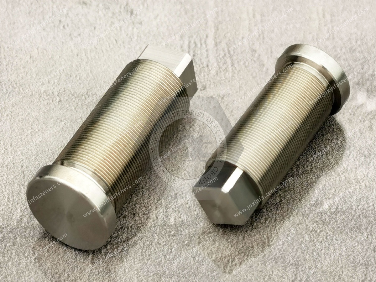
A useful way to design automated machinery is to separate five common mechanical functions.
A locating component establishes the relative position of two machine elements.
Typical components include:
dowel pins;
locating pins;
precision shoulders;
machined datum features.
A threaded fastener creates clamp load that holds joint members together.
Typical components include:
bolts;
screws;
nuts;
threaded studs.
A pivot component provides a controlled cylindrical interface around which another component rotates or oscillates.
Shoulder screws are commonly used for this function where appropriate.
A retention component prevents unwanted axial movement.
Examples include:
external retaining rings;
internal retaining rings;
circlips;
other shaft-retention hardware.
Depending on the joint architecture, shear or transverse loads may be transferred through:
dowel pins;
fitted shoulders;
joint friction generated by clamp load;
other purpose-designed interfaces.
This separation of functions can make machinery easier to design, manufacture, inspect, maintain, and second-source.
One common machine-design mistake is expecting ordinary clearance-hole bolts to precisely locate two machine plates.
A bolted joint can provide excellent clamp load, but clearance between the bolt and hole means the bolt position may not establish a repeatable datum.
If two plates must return to the same relative position after disassembly, dedicated locating features may be more appropriate.
A common architecture is:
Dowel Pins = Location
Bolts or Screws = Clamp Load
This allows each component to perform the function for which it was selected.
For automated equipment requiring repeatable tooling or fixture location, this distinction can be particularly valuable.
Dowel pins are used to establish controlled relative positioning between mating components.
Typical applications can include:
machine plates;
fixtures;
tooling assemblies;
gearbox housings;
actuator brackets;
equipment frames;
removable modules;
automation subassemblies.
The pin itself is only one part of the locating system.
Engineers must also consider the holes and datums that receive it.
The required fit depends on whether the pin should remain fixed, be removable, or allow repeated assembly.
Potential interface strategies include:
interference or press fit on one side;
controlled clearance on the mating component;
removable locating arrangements;
application-specific transition fits.
International fit systems such as ISO 286 may be used when appropriate to define shaft-and-hole tolerance relationships.
However, a tolerance designation should not be selected simply because it is commonly associated with dowel pins.
The fit should reflect:
pin diameter;
hole manufacturing process;
mating material;
assembly method;
required positioning accuracy;
service requirements;
expected disassembly;
temperature conditions.
More locating pins do not automatically produce better alignment.
If multiple rigid locating features attempt to control the same degrees of freedom without sufficient tolerance accommodation, the assembly can become over-constrained.
Possible consequences include:
difficult assembly;
binding;
forced misalignment;
distorted plates;
inconsistent installation;
increased sensitivity to thermal expansion.
A common engineering approach is to use locating geometry that establishes the required datum without unnecessarily constraining the assembly.
The exact strategy depends on the machine architecture and required degrees of freedom.
This is especially important for large automation frames, tooling plates, and assemblies exposed to temperature variation.
A shoulder screw typically combines:
a head;
a controlled-diameter unthreaded shoulder;
a threaded end.
The shoulder can function as a bearing surface, pivot, guide, spacer, or controlled locating feature.
Potential automation applications include:
linkage pivots;
guide mechanisms;
rollers;
cam-related assemblies;
movable brackets;
sliding mechanisms;
tooling components.
The thread secures the component.
The shoulder performs the mechanical interface function.
This distinction is important when specifying or second-sourcing shoulder screws.
A shoulder screw should not be sourced only by thread size.
Depending on the application, important dimensions may include:
shoulder diameter;
shoulder length;
thread size and pitch;
threaded length;
head diameter;
head height;
transition geometry;
under-head geometry;
overall length.
For a pivoting interface, the relationship between shoulder diameter and mating bore can influence clearance, play, friction, and wear.
For a spacing application, shoulder length may control assembled component position.
For this reason:
A shoulder screw with the correct thread but the wrong shoulder is not an equivalent component.
An important shoulder-screw design consideration is the relationship between shoulder length and the thickness of the component intended to move.
If the geometry causes the head or mating surface to clamp the moving component when the screw is tightened, the intended pivot may bind.
Engineers should therefore evaluate the complete axial stack:
shoulder length;
moving-component thickness;
washers or spacers;
mating surface;
threaded engagement;
required running clearance.
This is a good example of why nominal thread size alone cannot define a precision automation component.
Retaining rings provide compact axial retention for components installed on shafts or inside bores.
Typical retained components can include:
bearings;
gears;
pulleys;
rollers;
spacers;
bushings;
rotating components.
External retaining rings typically engage a groove on a shaft.
Internal retaining rings typically engage a groove inside a bore or housing.
Their compact geometry can eliminate the need for larger threaded collars or additional axial-retention hardware in suitable applications.
A retaining ring cannot be evaluated independently from its groove.
Critical interface characteristics can include:
shaft or bore diameter;
groove diameter;
groove width;
groove location;
groove edge condition;
retained-component geometry;
axial clearance.
If the groove geometry is incorrect, installing the correct nominal ring does not guarantee correct retention.
This is particularly important during second-source projects.
Procurement teams sometimes provide only the retaining-ring sample while the groove drawing remains unavailable.
For critical applications, both the ring and mating groove should be considered during technical review.
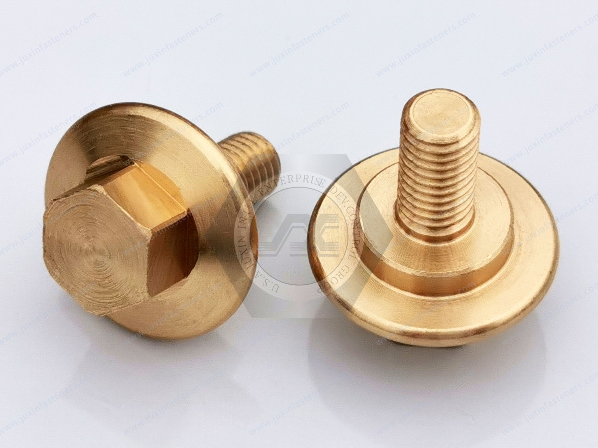
Press-fit and mechanically installed captive fasteners can be useful in automation equipment where designers want a permanent threaded or retention feature integrated into sheet metal or another suitable substrate.
Depending on the fastener type, advantages may include:
reduced loose-hardware handling;
repeatable attachment locations;
access to threads in thin material;
integration into production assembly;
captive hardware.
But press-fit performance depends on the interface.
Relevant factors may include:
panel material;
material hardness;
panel thickness;
mounting-hole dimensions;
edge distance;
installation force;
fastener geometry.
A press-fit fastener should therefore be qualified together with the intended parent material rather than as an isolated catalog item.
When an automated mechanism fails to align consistently, it is tempting to blame one pin, bolt, or fastener.
In reality, positional variation often accumulates through multiple dimensions.
A simplified stack might include:
Machine Datum → Mounting Hole → Locating Pin → Mating Hole → Bracket → Functional Component
Each interface contributes variation.
Therefore, tightening the tolerance on one fastener may not solve the complete alignment problem.
Engineers should identify which dimensions actually control the functional output and allocate tolerances accordingly.
This approach can reduce unnecessary precision on non-critical dimensions while concentrating manufacturing control on the interfaces that matter.
Automated machinery often contains both static and moving interfaces.
They require different design logic.
Used to establish position.
Used where intentional interference is required to retain a component or establish a fixed relationship.
Used where relative motion or easy assembly is required.
Selecting an interference fit where movement is needed can cause binding.
Selecting excessive clearance where repeatable location is required can create play.
The correct fit depends on function, material, temperature, manufacturing process, and maintenance strategy.
Automated machinery frequently accelerates, decelerates, indexes, reverses direction, and cycles repeatedly.
These motions can create:
cyclic shear loads;
impact loads;
vibration;
changing bearing loads;
repeated pivot motion;
preload variation.
Fastener selection should therefore consider the load path rather than simply choosing a higher-strength material.
For example, a dowel pin may be intentionally used to control location or transfer transverse load while bolts maintain clamp load.
A shoulder screw used as a pivot may need to be evaluated for bearing interaction and wear rather than only thread tensile capacity.
A retaining ring may be governed by the axial load transferred through its groove.
Each component should be evaluated according to its actual mechanical function.
Not every precision fastener experiences sliding motion.
But where a shoulder, pin, or other hardware component forms a moving interface, engineers should consider:
material pairing;
hardness;
surface finish;
lubrication;
contamination;
contact pressure;
motion frequency;
maintenance.
Simply specifying a hard fastener does not automatically create a low-wear interface.
The mating component may become the sacrificial surface, or an incompatible material pair may increase galling risk.
Bushings, lubrication, coatings, or alternative material combinations may be appropriate depending on the design.
These decisions should be based on the complete tribological interface rather than on the fastener alone.
Surface requirements for automation hardware may be specified for several reasons:
corrosion protection;
friction control;
appearance;
wear behavior;
electrical requirements;
dimensional fit.
These objectives should not be confused.
For example, a coating that improves corrosion resistance also changes component dimensions and may influence a close-fitting interface.
A coating or finish on a precision shoulder, locating pin, or press-fit surface should therefore be considered during tolerance definition.
For close-tolerance components, engineers should clearly define whether dimensions apply before or after coating when this is functionally important.
Automation equipment is often serviced repeatedly during its operating life.
Machine designers should consider how precision hardware affects maintenance.
Questions include:
Must the component return to the same position after removal?
Is the locating pin intended to remain in one member?
Can maintenance personnel access the retaining ring?
Can a shoulder screw be removed without dismantling adjacent assemblies?
Will repeated removal affect the fit?
Are replacement parts dimensionally interchangeable?
Does tooling require rapid changeover?
A design that is accurate but difficult to service can increase equipment downtime.
Serviceability should therefore be considered alongside precision.
The term “fasteners for automated equipment” has two meanings.
Fasteners may be used in automated machinery, and fasteners may also need to be installed automatically during machine production.
When automated feeding or installation is required, additional characteristics can become important:
orientation;
head geometry;
dimensional consistency;
feeding behavior;
tool access;
installation method;
part presentation;
process monitoring.
A component suitable for manual installation should not automatically be assumed suitable for automated feeding and installation.
Production engineering requirements should be defined during sourcing.
| Engineering Function | Potential Hardware | Key Interface to Control |
|---|---|---|
| Repeatable plate location | Dowel pin / locating pin | Pin-to-hole fit and datum strategy |
| Pivoting linkage | Shoulder screw | Shoulder diameter, length, mating bore |
| Structural clamping | Bolt / screw / nut | Preload and joint interface |
| Axial shaft retention | Retaining ring / circlip | Groove geometry and axial load |
| Thin-panel captive thread | Press-fit fastener | Hole, sheet thickness, material |
| Vibration-prone threaded joint | Appropriate locking fastener | Preload, locking mechanism, joint movement |
| Removable tooling | Locating + threaded fastening system | Repeatable location and serviceability |
This matrix is a starting point. Actual component selection should be based on the specific machine architecture.
Clearance-hole bolts may provide clamping without providing repeatable precision location.
Extremely tight tolerances can increase cost without improving machine performance.
A precision pin installed in an uncontrolled hole does not create a precision assembly.
The appropriate fit depends on whether the pin should be permanent, removable, or used repeatedly.
Surface treatments can change effective dimensions and fit.
Ring and groove form one retention system.
The shoulder usually controls the functional mechanical interface.
A mechanically accurate joint can still create unnecessary downtime if it cannot be serviced efficiently.
For procurement and supplier-development teams, second sourcing precision machine hardware requires more than matching an external appearance.
A useful principle is:
Visual Similarity ≠ Dimensional Equivalence ≠ Fit Equivalence ≠ Functional Equivalence
Determine whether the part:
locates;
clamps;
pivots;
retains;
transfers load;
spaces;
guides.
This identifies which dimensions are genuinely critical.
For a shoulder screw, these may include shoulder diameter and length.
For a dowel pin, diameter, length, and end geometry may matter.
For a retaining ring, the ring and groove interface must be understood.
For a press-fit fastener, the mounting-hole and substrate interface may be critical.
Where relevant, specify:
material grade;
mechanical properties;
hardness;
heat treatment;
corrosion requirements.
Do not assume two parts made from broadly similar material families are functionally equivalent.
Where functionally important, define:
coating;
surface finish;
lubrication;
corrosion protection;
critical uncoated or coated dimensions.
A second-source component should be evaluated in the interface where it will be used.
Depending on the component, this may include:
dimensional inspection;
fit evaluation;
assembly trials;
press installation;
pivot behavior;
axial retention;
functional cycling;
corrosion requirements.
The validation plan should reflect the real function of the part.
Precision machine components are particularly suitable for drawing-based sourcing because their functional requirements are often defined by a small number of critical interfaces.
A useful drawing should clearly distinguish:
Critical-to-Function Dimensions
from
General Manufacturing Dimensions
This helps both engineering and procurement teams focus supplier qualification on the characteristics that affect machine performance.
For an existing component without complete documentation, a physical sample can support dimensional cross-reference.
However, a sample alone may not reveal:
material grade;
hardness;
heat treatment;
coating specification;
original tolerance;
surface-finish requirement;
functional load requirement.
Where available, drawings and specifications should accompany the sample.
Before approving a second source for precision automated-equipment hardware, consider defining:
approved drawing revision;
critical dimensions;
dimensional tolerances;
fit requirements;
material;
hardness or heat treatment where applicable;
surface finish where functionally important;
coating;
mating component;
installation method;
operating environment;
dynamic or static load requirements;
inspection requirements;
sample-validation requirements;
packaging;
production quantity;
estimated annual usage.
The required documentation should be defined according to the actual OEM or machinery program rather than assumed universally.
For technical review and quotation, provide as much of the following information as applicable:
2D drawing;
3D CAD model where available;
existing or competitor reference part number;
physical sample for cross-reference projects;
component type;
critical dimensions and tolerances;
required fit;
mating-hole or shaft dimensions;
material specification;
hardness or heat-treatment requirements;
surface finish where specified;
coating;
operating environment;
static or dynamic loading information;
motion or wear requirements where applicable;
manual or automated installation requirements;
required inspection documentation;
sample quantity;
production quantity;
estimated annual usage.
JUXIN FASTENERS can use this information to evaluate standard product options, drawing-based requirements,
dimensional cross-reference feasibility, sample needs, and the appropriate production sourcing route.
Precision automation hardware should be selected according to mechanical function rather than according to product name alone.
For engineering teams, a useful decision path is:
Function → Datum / Load Path → Interface → Fit → Material → Surface Requirement → Installation → Maintenance → Validation
For procurement teams, the sourcing path continues:
Drawing or Existing Part → Critical-Characteristic Review → Cross-Reference → Sample Evaluation → Functional Validation → Second-Source Approval → Production RFQ
This creates a more reliable approach than simply searching for a component that looks similar to the existing part.
The objective is not to make every fastener “high precision.”
The objective is to control the dimensions and interfaces that actually determine machine performance.
Email: info@juxinfasteners.com
Website: www.juxinfasteners.com
 MORE NEWS
Sep. 30, 2026
Sep. 30, 2026
Sep. 30, 2026
Contact Us
Tel.:
+86 020 8621 0320
+86 020 3121 6067
E-mail:
Technical Support:
Navigation
SEND INQUIREY