
Call Us
+86 136 6007 9809
Call Us
+86 136 6007 9809

Aug. 14, 2026
Should engineers use an inverted cone chemical anchor or a conventional straight bonded anchor for a high-load concrete connection?
The answer cannot be determined from anchor shape alone.
A post-installed chemical anchoring system is a combination of:
Steel Anchor Element + Adhesive System + Concrete Substrate + Hole Geometry + Embedment + Edge Distance + Spacing
+ Installation Procedure + Service Environment + Technical Qualification
Inverted-cone geometry can change how forces are transferred into the surrounding concrete compared with a conventional straight threaded rod.
The original application concept combines adhesive bonding with geometry-dependent mechanical engagement and concrete bearing.
However, this leads to the most important engineering rule in this article:
Anchor Geometry ≠ Approved Load Capacity.
An inverted-cone design should not automatically be described as stronger, more fatigue-resistant, suitable for cracked concrete,
or suitable for seismic loading unless those characteristics are supported by the specific anchor system's engineering data, testing and applicable technical approval.
For structural engineers, design engineers, contractors, procurement managers and supplier-development teams, the correct selection path is:
Application → Concrete Condition → Load → Failure Mode → Anchor System → Adhesive → Embedment → Edge Distance & Spacing → Installation
→ Environment → Qualification → Inspection → Supplier Selection
A conventional straight bonded anchor typically uses a threaded rod or another steel anchoring element installed into a drilled hole with structural anchoring adhesive.
Its load transfer depends strongly on the interaction between:
Steel anchor element
Adhesive
Hole surface
Concrete substrate
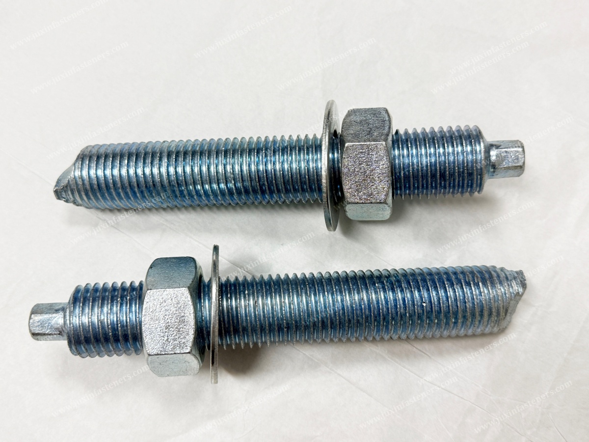
An inverted-cone chemical anchor incorporates a specially shaped embedded anchoring section.
Depending on the actual system design, this geometry can modify the transfer of tensile forces into the adhesive and surrounding concrete through
a combination of bonding, bearing and geometry-dependent mechanical engagement.
The practical distinction is therefore not simply:
Straight = Weak
Inverted Cone = Strong
The more accurate distinction is:
Different Anchor Geometry → Different Load-Transfer Behavior → Different Failure Modes and Qualification Requirements
One of the most important sourcing mistakes is treating the steel anchor element as if it alone determines structural performance.
It does not.
A chemical anchor system may include:
Anchor rod or specially formed anchor element
Adhesive resin
Concrete
Drilled hole
Hole-cleaning procedure
Installation equipment
Embedment depth
Curing conditions
Therefore:
Anchor Rod Strength ≠ Installed Anchor Capacity.
And:
Strong Steel ≠ Strong Concrete Connection.
Changing the rod, resin, embedment, drilling method or installation procedure can change the behavior of the installed anchoring system.
| Engineering Factor | Straight Bonded Anchor | Inverted-Cone Anchor |
|---|---|---|
| Steel element | Commonly straight threaded rod or specified anchoring element | Specially formed embedded geometry |
| Load transfer | Strongly dependent on adhesive/substrate interface | Adhesive plus geometry-dependent bearing/interlock behavior |
| Hole preparation | Critical | Critical |
| Adhesive selection | System-critical | System-critical |
| Embedment | Defined by qualified system/design | Defined by qualified system/design |
| Edge distance | Must be checked | Must be checked |
| Anchor spacing | Must be checked | Must be checked |
| Cracked concrete | Only where system is qualified | Only where system is qualified |
| Seismic use | Only where specifically qualified | Only where specifically qualified |
| Dynamic/fatigue loading | Requires appropriate engineering data | Requires appropriate engineering data |
| Installation sensitivity | Significant | Significant |
| Structural capacity | Product/system-specific | Product/system-specific |
The key conclusion is:
Different Load-Transfer Mechanism ≠ Universal Performance Advantage.
When a tensile force acts on a post-installed anchor, that load must eventually be transferred into the concrete member.
For a bonded anchor, load transfer may involve stresses along the adhesive interface between:
Anchor Element → Adhesive → Concrete
With specially formed anchor geometries, additional bearing or mechanical interaction may influence the load-transfer path.
But the surrounding concrete still has finite capacity.
This creates an important engineering reality:
Improving One Interface Can Shift Failure to Another Interface.
For example, if pull-out or bond resistance increases, another failure mode such as:
Steel failure
Concrete cone failure
Splitting
Edge breakout
may become governing.
This is why comparing anchors only by "pull-out strength" can be misleading.
A post-installed anchor can potentially fail through several mechanisms.
The steel anchoring element reaches its governing tensile or shear resistance.
The adhesive anchoring interface cannot sustain the applied load.
The anchoring system is pulled from the substrate through the governing system-specific mechanism.
A concrete failure surface develops around the anchor under tensile loading.
The anchoring force contributes to splitting of the concrete member.
Anchors located close to an edge can have reduced resistance because less concrete is available to develop the required load-transfer mechanism.
Real connections may experience simultaneous tension and shear rather than one isolated load direction.
Therefore:
Published Anchor Strength ≠ Connection Design Capacity.
The complete connection must be evaluated.
Suppose an engineer replaces a straight bonded anchor with an inverted-cone design.
Even if one part of the load-transfer mechanism improves, the engineer must still evaluate whether the governing failure mode changes.
For example:
Bond-Controlled Design → Concrete-Controlled Design
or:
Concrete-Controlled Design → Steel-Controlled Design
This is a critical Information Gain point for engineers and procurement teams:
A Higher-Capacity Anchor Element Does Not Necessarily Produce the Same Percentage Increase in Connection Capacity.
The surrounding concrete, edge distance, spacing and member thickness may become the limiting factors.
Depending on project location, application and product qualification, structural anchor design may reference frameworks such as:
EN 1992-4 — Design of fastenings for use in concrete
Applicable European Assessment Documents (EADs) and European Technical Assessments for post-installed anchor systems
ACI 318 Chapter 17 — Anchoring to Concrete
Applicable ICC-ES criteria and evaluation documentation for post-installed adhesive anchor systems
Project-specific structural specifications
Manufacturer-specific approved design data
The governing standard depends on the project and anchor system.
A critical procurement rule is:
Standard Reference ≠ Product Approval.
Listing EN 1992-4 or ACI 318 on a quotation does not prove that a specific anchor system has the technical qualification required for a particular structural application.
For structural anchoring, procurement should distinguish between:
A supplier saying a product is "suitable for concrete"
A product having test data
A complete anchoring system having applicable technical assessment or qualification for the required condition
These are not equivalent.
For demanding projects, verify whether the documentation covers the actual conditions, including where relevant:
Cracked concrete
Uncracked concrete
Static loading
Seismic loading
Fire exposure
Installation orientation
Concrete strength
Temperature
Hole drilling method
Adhesive system
Anchor diameter
Embedment
Therefore:
Product Description ≠ Application Qualification.
Concrete should not automatically be treated as an uncracked, homogeneous substrate.
Cracks may develop because of:
Structural loading
Shrinkage
Temperature effects
Settlement
Seismic action
Long-term structural behavior
An anchor qualified only for one concrete condition should not automatically be assumed suitable for another.
The correct rule is:
Performance in Uncracked Concrete ≠ Performance in Cracked Concrete.
If cracked-concrete performance is required, the specific anchor system must have appropriate design data or qualification for that condition.
It is tempting to assume that an anchor with greater mechanical engagement is automatically suitable for earthquakes.
That is unsafe.
Seismic loading can involve:
Load reversals
Cyclic tension
Cyclic shear
Crack opening and closing
Concrete damage
Connection displacement
Therefore:
Mechanical Interlock ≠ Seismic Qualification.
Only use an anchor for seismic applications when the specific anchoring system has appropriate qualification and design data for the required seismic condition.
Industrial machinery, transportation infrastructure and other equipment can subject anchors to repeated loading.
Potential sources include:
Rotating machinery
Compressors
Pumps
Industrial presses
Conveyors
Production equipment
Transportation systems
But another important distinction is necessary:
Vibration ≠ Automatically Fatigue Qualification.
An anchor that performs well under static pull-out testing should not automatically be assumed suitable for high-cycle dynamic loading.
Where fatigue or dynamic loading governs the design, use appropriate product-specific engineering data and project requirements.
A dangerous assumption is:
"The inverted cone mechanically locks into the concrete, so hole cleaning is less important."
This should not be used as a general engineering rule.
Where adhesive remains part of the load-transfer system, drilling dust and contamination can influence anchoring performance.
Possible contaminants include:
Concrete dust
Loose drilling debris
Water
Oil
Construction contamination
Therefore:
Mechanical Engagement ≠ Permission to Ignore Hole Cleaning.
The exact cleaning sequence must follow the qualified anchor/adhesive system's installation instructions.
Anchor performance may depend on how the hole is produced.
Possible drilling methods can include:
Hammer drilling
Rotary drilling
Diamond drilling
The resulting hole surface can differ.
An adhesive anchoring system qualified with one drilling method should not automatically be assumed equivalent under another method unless supported by the applicable system documentation.
Therefore:
Same Hole Diameter ≠ Same Hole Condition.
Anchor installation requires more than drilling "approximately the right hole."
Important parameters include:
Nominal anchor diameter
Specified hole diameter
Hole depth
Effective embedment
Anchor position
Adhesive volume
Embedment depth affects how forces are transferred into the concrete.
But:
Deeper Embedment ≠ Unlimited Capacity Increase.
At some point, another failure mode or geometric constraint may govern.
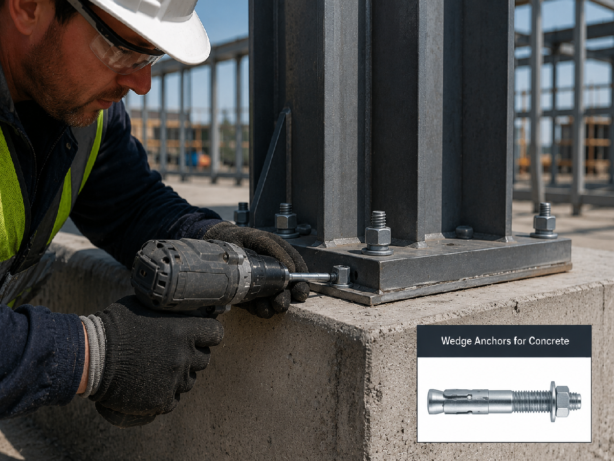
Concrete anchors need sufficient surrounding concrete.
When an anchor is installed near an edge, the available concrete volume may be reduced.
Potential consequences include:
Edge breakout
Splitting
Reduced tensile resistance
Reduced shear resistance
This means an anchor that performs well in a large test block may behave differently near an actual structural edge.
Therefore:
Anchor Capacity ≠ Independent of Edge Distance.
Multiple anchors can interact.
If anchors are installed too close together, their concrete stress or failure zones can overlap.
The group cannot automatically be designed as:
Single-Anchor Capacity × Number of Anchors
Load distribution, spacing and concrete failure mechanisms must be considered.
Therefore:
Four Anchors ≠ Automatically Four Times the Capacity of One Anchor.
This is particularly important for:
Base plates
Machinery foundations
Structural brackets
Equipment frames
A deep anchor cannot be considered independently from the concrete member containing it.
The design should consider:
Member thickness
Embedment
Opposite surface
Reinforcement
Edge geometry
Drilling depth
A larger anchor is not automatically the correct solution for a thin concrete member.
Chemical anchors depend on the selected resin system.
Important variables can include:
Resin chemistry
Concrete condition
Installation temperature
Service temperature
Cure time
Hole condition
Moisture
Anchor geometry
Product qualification
Therefore:
Same Anchor Rod + Different Adhesive ≠ Same Anchor System.
Changing adhesive can require engineering review.
The adhesive must reach the required cure condition before the anchor is loaded according to the system instructions.
Cure time can depend on:
Adhesive formulation
Concrete temperature
Ambient temperature
Installation conditions
A schedule that works in warm conditions may not be appropriate in colder conditions.
Therefore:
Installed ≠ Ready for Full Load.
These are different engineering conditions.
Installation temperature affects:
Resin handling
Mixing
Injection
Cure time
Service temperature can affect:
Long-term adhesive behavior
Material properties
Structural resistance
Do not treat one temperature specification as the other.
Incomplete adhesive filling can compromise the intended load-transfer interface.
Installation should follow the approved procedure for the specific system.
Depending on the system, injection from the appropriate location within the hole can help control:
Air entrapment
Incomplete filling
Uneven resin distribution
But installation instructions should not be improvised from a generic article.
Generic Installation Advice ≠ Manufacturer Installation Instructions.
Structural design calculations assume that the anchor is installed correctly.
Real construction sites introduce variation.
Possible installation errors include:
Wrong drill diameter
Insufficient hole depth
Poor hole cleaning
Incorrect resin
Expired adhesive
Incorrect mixing
Air voids
Wrong embedment
Loading before cure
Incorrect installation temperature
This leads to a powerful design principle:
Calculated Capacity ≠ Installed Capacity When Installation Is Incorrect.
For safety-critical connections, installation quality is part of structural reliability.
Industrial machinery can impose:
Static tension
Shear
Vibration
Cyclic loading
Impact
Overturning moments
Potential applications include:
CNC machinery
Industrial presses
Compressors
Pumps
Production lines
Material-handling equipment
The anchor should be selected from the actual machine loads and qualified anchoring system—not simply from machine weight.
Heavy Machine ≠ Automatically Large Anchor.
Load path and foundation design matter.
Anchoring steel structures or equipment frames to concrete requires the complete connection to be considered.
Relevant variables include:
Anchor layout
Base-plate stiffness
Tension distribution
Shear transfer
Grout
Edge distance
Anchor spacing
Concrete strength
Member thickness
The anchor is one component within the connection.
Strong Anchor ≠ Strong Base-Plate Connection.
Chemical anchoring systems may be considered for selected infrastructure applications involving:
Structural brackets
Equipment supports
Barriers
Retrofit connections
Utility supports
Steel-to-concrete attachments
However, infrastructure applications often have project-specific requirements.
Anchor selection should therefore follow the governing structural design, product qualification and installation requirements.
Potential anchoring applications can include:
Trackside equipment
Cable support systems
Signage
Electrical equipment
Equipment brackets
Secondary infrastructure attachments
But transportation applications require careful distinction between general equipment fastening and safety-critical structural systems.
Concrete Anchor Supply ≠ Rail Safety Qualification.
Safety-critical rail applications require the applicable project/OEM requirements and formal validation.
In seismic regions, anchors may be required to perform under cracked concrete and cyclic loading conditions.
An inverted-cone geometry may be technically interesting, but geometry cannot substitute for qualification.
For seismic sourcing, procurement should request:
Applicable approval
Qualified anchor configuration
Concrete conditions
Seismic category or applicable design data
Installation instructions
Adhesive identification
Anchor dimensions
Embedment
Environmental limits
A concrete anchor should not automatically be transferred to another substrate.
Natural stone can vary substantially in:
Strength
Porosity
Cracking behavior
Mineral structure
Masonry presents another set of substrate conditions.
Therefore:
Approved for Concrete ≠ Approved for Natural Stone or Masonry.
Substrate-specific engineering verification is required.
The steel anchor element must also survive the service environment.
Possible material or surface-treatment considerations can include:
Carbon steel with appropriate coating
Stainless steel
Application-specific corrosion protection
Selection depends on:
Indoor/outdoor exposure
Moisture
Chlorides
Chemicals
Temperature
Design life
But:
Corrosion-Resistant Anchor Rod ≠ Corrosion-Resistant Connection.
The complete assembly and environment must be evaluated.
Stainless steel may be considered for corrosive environments.
But:
Stainless Steel ≠ Corrosion-Proof.
Grade selection should consider:
Chloride exposure
Chemicals
Crevice conditions
Temperature
Galvanic interaction
304 and 316 stainless steels should not be treated as universally interchangeable.
And:
316 ≠ Automatically the Correct Anchor Material.
The qualified system satisfies the design load
Conventional bonded load transfer is appropriate
Installation conditions match the system qualification
Required edge distance and spacing are available
Static or specified loading is within approved design conditions
Project economics favor the conventional system
Its geometry provides a useful load-transfer mechanism for the application
The required performance is supported by system-specific engineering data
The selected adhesive and anchor geometry are qualified together
Project conditions match the available technical assessment
The complete system provides a design advantage over the conventional alternative
The correct rule is:
Select From Qualified Performance, Not From Shape Alone.
| Project Question | Why It Matters |
|---|---|
| Cracked or uncracked concrete? | Can change applicable anchor qualification and resistance |
| Static, dynamic or seismic loading? | Determines required engineering evidence |
| Tension, shear or combined load? | Changes governing failure mechanism |
| Required embedment? | Influences load transfer and concrete behavior |
| Edge distance? | Can govern concrete failure |
| Anchor spacing? | Group interaction can reduce resistance |
| Member thickness? | Limits available concrete volume and embedment |
| Which adhesive? | Part of the anchoring system |
| Installation temperature? | Influences adhesive installation and curing |
| Service temperature? | Can influence long-term system performance |
| Corrosion environment? | Influences anchor material/coating |
| Which approval applies? | Determines whether the system is qualified for the application |
| Observed Problem | Possible Root Cause | Engineering Review |
|---|---|---|
| Anchor pulls from hole | Bond, installation, embedment or substrate issue | Adhesive, cleaning, hole, qualification |
| Concrete cone failure | Concrete governs | Embedment, spacing, edge distance, concrete |
| Edge breakout | Insufficient edge condition | Anchor position and structural geometry |
| Splitting | Concrete geometry or installation condition | Spacing, edge distance, member thickness |
| Steel fracture | Steel element governs | Material, diameter and applied load |
| Excessive displacement | System stiffness or installation | Anchor system and connection design |
| Early adhesive failure | Installation or environmental mismatch | Cleaning, resin, temperature, cure |
| Group performs below expected sum | Anchor interaction | Group design and load distribution |
| Seismic application lacks evidence | Qualification gap | Technical approval and project requirements |
| Corrosion damage | Material/environment mismatch | Material, coating and exposure |
The correct response to anchor failure is not automatically:
Use a Larger Anchor.
A larger anchor may still fail if the actual problem is:
Edge distance
Concrete thickness
Hole cleaning
Wrong adhesive
Installation
Group interaction
Second-source development requires particular caution because an anchor system is more than a steel component.
A replacement should not be approved only because it has:
Same diameter
Same length
Same thread
Similar appearance
Compare:
Drawing + Anchor Geometry + Material + Mechanical Properties + Surface Treatment + Adhesive System + Embedment
+ Installation Procedure + Concrete Condition + Design Data + Testing + Technical Qualification + Documentation + Change Control
Therefore:
Same Dimensions ≠ Functional Equivalence.
And:
Same Anchor Rod ≠ Same Anchoring System.
This depends on the system.
If the anchoring system's technical qualification identifies a specific anchor element, adhesive and installation configuration, substituting one component may change the qualified system.
Procurement should therefore determine whether:
The anchor element is proprietary
Material is specified
Geometry is controlled
Adhesive compatibility is defined
Technical approval permits substitution
A dimensional copy should never automatically be assumed to preserve structural qualification.
Procurement and supplier-development teams should ask:
What exact anchor component is being supplied?
What material is specified?
What mechanical properties are required?
What thread specification applies?
What surface treatment applies?
Is the anchor part of a qualified anchoring system?
Which adhesive is intended?
Which approval or assessment applies?
Does the qualification cover cracked concrete?
Does it cover seismic loading where required?
Which anchor diameters and embedments are covered?
What installation instructions apply?
What documentation is supplied?
How are production changes controlled?
For critical structural projects, a generic product catalogue is not sufficient engineering evidence.
Professional sourcing should evaluate:
Total Installed Cost = Anchor + Adhesive + Drilling + Hole Cleaning + Installation Labor + Cure Time + Inspection + Rework + Downtime + Maintenance + Structural Risk + Supply Risk
This creates an important procurement principle:
Lowest Anchor Price ≠ Lowest Installed Cost.
A higher-priced anchoring system may be commercially justified if it provides a verified design advantage.
But that advantage should be demonstrated through engineering—not marketing terminology.
Potentially, but never automatically.
Reducing anchor count changes:
Base-plate load distribution
Concrete stresses
Edge distances
Spacing
Connection stiffness
Redundancy
Any reduction in anchor quantity requires connection redesign and verification.
Therefore:
Higher Individual Anchor Capacity ≠ Automatic Reduction in Anchor Quantity.
Structural and mechanical engineers commonly search questions such as:
What is an inverted cone chemical anchor?
Inverted cone vs. straight chemical anchor: which is better?
How do bonded anchors transfer load?
Which chemical anchor is suitable for cracked concrete?
How does anchor embedment affect capacity?
Why does anchor edge distance matter?
Why do chemical anchors fail?
Are chemical anchors suitable for seismic applications?
How should machinery be anchored to concrete?
Does an inverted cone anchor require hole cleaning?
Can I change the adhesive used with an anchor rod?
A useful supplier page should answer these questions before requesting an RFQ.
Commercial searches may include:
Chemical anchor manufacturer
Concrete anchor supplier
Inverted cone anchor supplier
Bonded anchor supplier
Custom anchor rod manufacturer
Mechanical anchor supplier
OEM concrete anchoring components
Second-source chemical anchor components
Industrial anchor manufacturer
Procurement should distinguish between:
Manufacturing the Steel Component
and:
Providing a Qualified Structural Anchoring System
These are not automatically the same capability.
JUXIN FASTENERS can evaluate drawing-based and specification-based fastening components for construction, industrial equipment and infrastructure applications.
Relevant product categories include:
Concrete screw anchors
Concrete self-tapping anchors
Mechanical anchoring components
Chemical anchoring components
Anchor rods
Industrial fasteners
Structural fastening components
Custom drawing-based fasteners
For OEM or project sourcing, requirements can be reviewed for:
Dimensions
Material
Thread
Mechanical properties
Surface treatment
Corrosion protection
Packaging
Inspection
Production specifications
For structural applications, the distinction between manufacturing capability and system qualification must remain clear.
JUXIN FASTENERS does not treat component supply alone as evidence that a complete anchor system is approved for a specific structural,
cracked-concrete, seismic or safety-critical application.
Where project-specific technical approval is required, the applicable system documentation should be defined during sourcing.
It is a post-installed anchoring concept using a specially shaped embedded anchor section together with an adhesive system.
Depending on the system, the geometry can introduce additional bearing or mechanical engagement into the load-transfer mechanism.
Not universally. Performance depends on anchor geometry, adhesive, concrete, embedment, edge distance, spacing, installation and technical qualification.
No. Seismic suitability requires system-specific qualification and applicable engineering data.
Only when the specific system is qualified for the required cracked-concrete condition.
Not where the system is designed and qualified as a combined adhesive anchoring system.
Follow the specific qualified system instructions. Mechanical engagement should not be assumed to eliminate hole-cleaning requirements.
No. Increasing embedment can change load transfer, but concrete geometry, edge distance, member thickness, steel strength and other failure modes may govern.
Do not assume equivalence. The adhesive can be an integral part of the qualified anchoring system.
No. A larger anchor cannot correct insufficient edge distance, inadequate concrete thickness, poor installation or an inappropriate anchoring system.
The presence of adhesive does not automatically establish waterproofing of the complete penetration or connection.
Provide the anchor drawing/specification, dimensions, material, concrete condition, loads, embedment, edge distance, spacing,
environment, surface treatment, applicable approval requirements and quantity.
Potentially, depending on the project. However, for a qualified structural anchoring system, component substitution must be reviewed against the applicable system documentation.
No. Seismic suitability requires appropriate product/system qualification and engineering evidence.
No. Geometry, material, mechanical properties, surface treatment, adhesive compatibility, system qualification and installation requirements may also need to match.
A supplier can manufacture an anchor component. Structural qualification concerns the performance of the defined anchoring system under specified conditions.
For faster engineering and commercial review, provide:
2D drawing
3D model where available
Part number
Drawing revision
Anchor type
Anchor geometry
Anchor diameter
Thread specification
Overall length
Material
Mechanical property requirement
Surface treatment
Corrosion requirement
Concrete strength
Cracked or uncracked concrete
Concrete member thickness
Hole diameter
Hole depth
Effective embedment depth
Edge distance
Anchor spacing
Number of anchors
Tensile load
Shear load
Combined loading
Static loading
Dynamic/fatigue loading where applicable
Seismic requirement where applicable
Adhesive system
Installation method
Drilling method
Installation temperature
Service temperature
Moisture condition
Cure requirements
Applicable design standard
Required technical assessment or approval
Inspection requirement
Material documentation
Packaging
Project quantity
Annual volume
Existing approved sample for second-source projects
For second-source development, also provide the current approved anchor-system documentation where permitted.
This helps determine whether the project involves:
Component Manufacturing
or:
Qualified Anchoring-System Equivalence
That distinction should be established before quotation.
This article should connect internally with existing JUXIN FASTENERS resources covering:
Concrete Screw Anchors
Mechanical Anchoring Solutions
Custom Anchor Bolts and Anchor Rods
Fastener Material Selection
ISO Metric Thread Tolerances and Inspection
Fastener Surface Finish Selection
Zinc Plating vs. Zinc-Nickel Coating
Stainless Steel Fastener Material Selection
Bolt and Nut Strength Classes
Industrial Machinery Fastening Solutions
Rail and Transportation Fastening Solutions
Construction and Infrastructure Fastening Solutions
Supplier Qualification and Second-Source Development
Use the existing indexed JUXIN FASTENERS URL when implementing each internal link.
The intended internal content path is:
Concrete Anchoring → Anchor Type → Load Transfer → Concrete Failure Mode → Installation → Material & Corrosion → Technical Qualification → Supplier Qualification → RFQ
The most important lesson in chemical anchoring is that structural performance does not come from anchor geometry alone.
It comes from the interaction of:
Anchor Element + Adhesive + Concrete + Embedment + Edge Distance + Spacing + Installation + Environment + Qualification
Remember:
Anchor Geometry ≠ Approved Load Capacity.
Anchor Rod Strength ≠ Installed Anchor Capacity.
Strong Steel ≠ Strong Concrete Connection.
Different Load-Transfer Mechanism ≠ Universal Performance Advantage.
Performance in Uncracked Concrete ≠ Performance in Cracked Concrete.
Mechanical Interlock ≠ Seismic Qualification.
Vibration ≠ Automatically Fatigue Qualification.
Same Hole Diameter ≠ Same Hole Condition.
Same Anchor Rod + Different Adhesive ≠ Same Anchor System.
Four Anchors ≠ Automatically Four Times Single-Anchor Capacity.
Standard Reference ≠ Product Approval.
Product Description ≠ Application Qualification.
Same Dimensions ≠ Functional Equivalence.
For structural and design engineers, this framework helps identify the governing failure mode rather than selecting anchors from diameter or marketing claims.
For procurement and supplier-development teams, it creates a clearer distinction between buying a steel anchor component and qualifying a complete structural anchoring system.
For OEMs and contractors, it provides a more reliable RFQ path by defining concrete condition, loading, embedment, spacing, environment and qualification requirements before supplier selection.
JUXIN FASTENERS supports drawing-based concrete anchors, mechanical anchoring components, chemical anchoring components, anchor rods,
industrial fasteners and custom engineered fastening components for OEM, construction, infrastructure and industrial applications.
For a new project or second-source evaluation, send your drawing, anchor specification, concrete condition, loading requirements, material, surface treatment,
applicable technical requirements and project quantity for review.
JUXIN FASTENERS
Email: info@juxinfasteners.com
Website: www.juxinfasteners.com
Contact Us
Tel.:
+86 020 8621 0320
+86 020 3121 6067
E-mail:
Technical Support:
Navigation
SEND INQUIREY



