Call Us
+86 136 6007 9809
Call Us
+86 136 6007 9809

Sep. 02, 2026
In high-volume plastic manufacturing, creating a reliable metal thread inside a molded polymer component is not simply a fastener-selection decision.
It is a manufacturing architecture decision.
Automotive housings, EV components, electronic enclosures, medical diagnostic equipment, smart meters, industrial controls,
telecom equipment and consumer products may require hundreds of thousands or millions of threaded plastic assemblies per year.
At these volumes, the choice between molded-in threaded inserts and post-mold threaded inserts can affect injection molding cycle time, mold complexity, automation CapEx, scrap exposure, assembly labor, mechanical performance and total cost of ownership.
The two primary approaches are:
Molded-in inserts / insert molding: the metal insert is positioned inside the injection mold before polymer injection.
Post-mold inserts: the plastic component is molded first and the threaded insert is installed afterward using heat staking, ultrasonic insertion, press-fit or another secondary process.
Neither method is universally better.
The correct engineering decision depends on the resin, insert geometry, boss design, required mechanical performance, annual volume, cavity count, tooling architecture, automation strategy and total installed cost.
This guide provides a practical engineering and sourcing framework for making that decision.

Choose molded-in inserts when direct integration into the molding process, deep mechanical engagement,
thermoset compatibility or elimination of downstream insertion operations justifies the additional tooling and cycle-time complexity.
Choose post-mold inserts when maximum molding press productivity, tooling flexibility, design-change flexibility or controlled secondary installation provides a better overall manufacturing economics.
For high-volume OEM programs, the decision should not be based on insert price alone.
The relevant comparison is:
Insert Cost + Tooling Cost + Molding Cycle Cost + Secondary Assembly Cost + Automation Cost + Scrap Risk + Quality Cost + Changeover Cost
That is the real TCO.
             MOLDED-IN INSERT PROCESS

        Metal Insert Loaded on Core Pin
                       │
                       ▼
             ┌─────────────────┐
             │ Injection Mold  │
             │ Resin Injection │
             └────────┬────────┘
                      │
                      ▼
          Polymer Encapsulates
          External Insert Geometry
                      │
                      ▼
              Cooling / Ejection
                      │
                      ▼
             Finished Threaded Part
The metal insert is positioned on a mold core pin or another locating feature before the mold closes.
Molten polymer then flows around the external geometry of the insert.
Depending on the insert design, the polymer may engage:
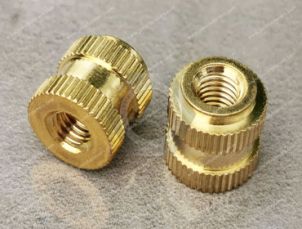
knurls
annular grooves
undercuts
ribs
hexagonal sections
flanges
other mechanical locking features
The insert becomes integrated into the molded component as the polymer solidifies.
             POST-MOLD INSERT PROCESS

          Injection Mold Plastic Boss
                      │
                      ▼
               Molded Hole/Boss
                      │
                      ▼
          Heat / Ultrasonic / Press
                      │
                      ▼
             Insert Installed
                      │
                      ▼
              Finished Threaded Part
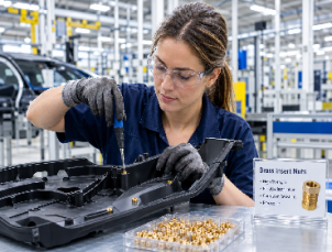
The plastic component is molded without the metal insert.
After ejection and cooling, the threaded insert is installed into a prepared hole or boss.
Common methods include:
heat staking
ultrasonic insertion
cold press-fit
barbed insertion
expansion insertion
other application-specific installation processes
This separation between molding and insert installation can provide substantial flexibility in high-volume manufacturing.
The difference between molded-in and post-mold insertion is not simply “one happens during molding and one happens afterward.”
The two processes create different mechanisms for transferring mechanical loads from the metal insert into the polymer.
During insert molding, the insert is already positioned inside the mold when the polymer is injected.
The molten polymer flows around the external locking geometry.
        Molten Polymer Flow

              ↓↓↓↓↓↓↓↓↓
        ┌─────────────────┐
        │       │ │       │
        │     ╱████╲      │
        │    ╱ ████ ╲     │
        │   ║  INSERT ║    │
        │    ╲ ████ ╱     │
        │     ╲████╱      │
        └─────────────────┘

        Polymer fills external
        knurls / grooves / undercuts
Injection pressure varies substantially with machine, gate design, resin, geometry, melt temperature and process conditions.
In many injection molding applications, cavity pressures can fall within the broad range of hundreds to more than 1,000 bar.
The important engineering point is not a single pressure number.
It is that the polymer is being forced around the insert's external locking geometry while the material is still molten.
This can create strong mechanical engagement with:
deep undercuts
circumferential grooves
knurled surfaces
hexagonal sections
flanged geometries
The external geometry of the insert therefore becomes an important part of the load-transfer system.
Molded-in inserts can provide high axial and rotational resistance when the surrounding boss geometry, resin and insert geometry are correctly designed.
However, strength is not determined by the insert alone.
It is a system property involving:
Insert Geometry + Polymer Strength + Engagement Area + Boss Geometry + Molding Conditions
One of the most important considerations in insert molding is differential thermal contraction.
Metal and polymer generally have different coefficients of thermal expansion.
During cooling, the polymer shrinks around the relatively rigid metal insert.
This can generate local radial and circumferential stresses around the boss.
In crack-sensitive polymers, particularly some amorphous materials, excessive residual stress combined with environmental exposure can contribute to:
boss cracking
environmental stress cracking
deformation
long-term dimensional instability
This is why molded-in insert design should consider not only immediate pull-out strength but also residual stress and long-term reliability.
Post-mold insertion separates plastic molding from threaded-insert installation.
The boss is molded first.
The insert is installed after the polymer component has cooled.
During heat staking, controlled thermal energy softens or melts a localized region of polymer around the insert.
The insert moves into the prepared hole while the softened polymer flows around its external geometry.
       Heated Insert
            ↓
       ┌─────────┐
       │ INSERT  │
       └────┬────┘
            ↓
       ╔═══════════╗
       ║  softened ║
       ║  polymer  ║
       ╚═══════════╝
            ↓
       Polymer flows
       into knurls
The actual remelted layer depends on:
resin
insert diameter
insert geometry
hole diameter
probe temperature
insertion speed
dwell time
machine control
boss geometry
A localized remelt zone on the order of fractions of a millimeter can occur in some applications, but this should be treated as a process-dependent value rather than a universal specification.
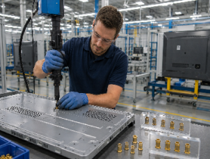
Ultrasonic insertion uses high-frequency mechanical vibration to generate localized heating at the polymer/insert interface.
It can be highly suitable for automated production where:
insertion force must be controlled
cycle time must be short
repeatability is important
large production volumes justify dedicated equipment
Cold press-fit installation avoids thermal processing.
The insert is mechanically driven into a prepared hole.
This approach can be effective when:
resin strength is adequate
hole dimensions are tightly controlled
the insert geometry is designed for interference or mechanical retention
installation force remains within the boss's structural limits
Press-fit should not be treated as interchangeable with heat staking or ultrasonic insertion. Resin, hole tolerance and insert geometry must be evaluated together.
The following framework illustrates why process architecture becomes increasingly important as production volume increases.
| Manufacturing Parameter | Molded-In Inserts | Post-Mold Inserts |
|---|---|---|
| Injection molding cycle | Can increase due to insert loading | Plastic molding cycle remains independent of insert loading |
| Secondary assembly | Potentially eliminated | Required |
| Mold complexity | Higher | Lower |
| Insert loading | Inside molding cycle | Separate operation |
| Tooling flexibility | Lower | Higher |
| Design revisions | May require mold changes | Often easier to implement |
| Mold steel exposure | Metal inserts enter mold | Metal inserts stay outside mold |
| Automation | Robot/shuttle loading may be required | Bowl feeder + insertion press may be used |
| Floor-space requirement | Lower downstream requirement | Secondary cell required |
| Scrap containment | Molded-in defects can affect complete shots | Defective inserts may be isolated during secondary assembly |
| High-cavity scalability | Requires careful loading architecture | Molding cycle remains independent of insert feeding |
Cycle time is one of the most important economic variables in high-volume insert molding.
Consider an illustrative 16-cavity tool:
| Process | Molded-In Strategy | Post-Mold Strategy |
|---|---|---|
| Base molding cycle | 20 sec | 20 sec |
| Insert loading allowance | +12 sec | +0 sec |
| Illustrative molding cycle | 32 sec | 20 sec |
| Theoretical shots/hour | 112.5 | 180 |
| Theoretical molded parts/hour | 1,800 | 2,880 |
| Secondary installation | None | Separate automated cell |
The numbers above are an illustrative manufacturing model, not a guaranteed production result.
Actual cycle time depends on:
cavity count
insert quantity per component
insert loading method
robot motion
mold opening distance
safety interlocks
cooling time
resin
part geometry
machine configuration
automation architecture
The important relationship is:
Molding Output = Cavity Count × 3,600 / Effective Cycle Time
Even a relatively small increase in molding cycle time can become economically significant when multiplied by millions of parts.
In some insert-molding architectures, the additional insert loading and positioning sequence can create a significant increase in effective cycle time.
An illustrative range of 15–40% cycle-time impact can occur depending on the loading architecture and number of inserts per shot.
However, this should never be treated as a universal penalty.
A highly automated system with optimized robotic loading may have a very different result from manual insert loading.
Therefore, OEM tooling teams should compare:
Base Cycle Time
versus
Base Cycle Time + Insert Loading + Position Verification + Mold Closure Safety Time
rather than comparing only the fastener unit price.
Molded-in inserts introduce a unique tooling requirement:
the insert must remain correctly positioned while the mold closes and polymer is injected.
This makes core-pin retention and insert positioning critical.
The insert may be located using:
precision core pins
internal thread engagement
pilots
flats
anti-rotation features
magnetic retention
vacuum retention
mechanical retention
robotic placement systems
The appropriate solution depends on insert geometry and mold architecture.
An improperly seated insert can create several problems:
insert tilt
flash
thread contamination
core-pin damage
cavity damage
dimensional variation
incomplete encapsulation
In multi-cavity molds, one positioning error can become particularly expensive because the affected cavity may generate defective parts during the shot.
Molded-in insert programs also introduce a specific tooling risk.
If a metal insert is not correctly seated and becomes trapped between mold components during closure, the metal component can potentially damage:
core pins
cavity steel
parting surfaces
slides
shut-offs
The severity depends on mold design and the location of the displaced insert.
This is one reason why automated insert verification and positive retention become increasingly important in high-volume production.
Consider a tool with:
8 cavities
16 cavities
32 cavities
64 cavities
As cavity count increases, the number of inserts that must be loaded and verified per cycle can increase substantially.
This does not automatically make molded-in insertion uneconomical.
Instead, it shifts the engineering question toward:
Can the insert-loading architecture maintain the required cycle time and positioning reliability?
Possible solutions include:
multi-position robotic end effectors
rotary shuttle systems
dedicated insert loading stations
automated vision verification
preloaded carrier systems
Post-mold insertion moves this complexity outside the injection mold.
Resin selection is one of the most important variables in choosing between molded-in and post-mold threaded inserts.
The process should be selected based on the actual polymer grade rather than simply the generic resin family.
Important variables include:
melting temperature
crystallinity
glass-transition behavior
shrinkage
fiber content
moisture sensitivity
chemical resistance
environmental stress cracking
thermal expansion
long-term creep and stress relaxation
Examples include:
PC
ABS
PC/ABS
PMMA
PS
Amorphous polymers generally soften over a temperature range rather than having the sharp melting transition associated with crystalline materials.
For some crack-sensitive applications, post-mold heat staking can provide greater process control because localized thermal energy is applied after the initial molding and cooling process.
However, molded-in inserts can also be used successfully when the boss geometry, insert geometry and molding conditions are properly engineered.
The decision should therefore be based on resin grade + boss geometry + stress level + environmental requirements, not simply the word “amorphous.”
Examples include:
PA6
PA66
PBT
POM
PEEK
These materials can exhibit significant shrinkage and dimensional changes during cooling.
For molded-in applications, polymer shrinkage around external insert features can create strong mechanical engagement.
For post-mold installation, heat-staking or ultrasonic parameters must be matched to the resin's thermal characteristics.
Incorrect thermal settings can result in:
insufficient polymer flow
excessive polymer degradation
weak retention
boss deformation
inconsistent seating
Examples include:
PA66-GF30
PA66-GF50
PBT-GF
other reinforced engineering polymers
Glass fibers can significantly increase stiffness while reducing ductility.
This changes how the boss responds to insertion forces and local stress.
For cold press-fit applications, excessive interference can cause:
cracking
fiber-matrix separation
local boss fracture
Heat staking or molded-in insertion may therefore be more appropriate depending on the component geometry and load requirement.
But even here, “glass-filled” does not automatically determine the process.
The actual:
fiber content + resin grade + boss geometry + hole tolerance + insert geometry
must be evaluated together.
Thermoset materials such as:
epoxy compounds
phenolic compounds
Bakelite-type materials
undergo irreversible cross-linking during curing.
They cannot simply be re-melted like thermoplastics.
Therefore, conventional heat staking is generally not applicable in the same way it is for thermoplastic materials.
For thermoset components, engineers may consider:
molded-in inserts
mechanically retained inserts
expansion inserts
application-specific anchoring systems
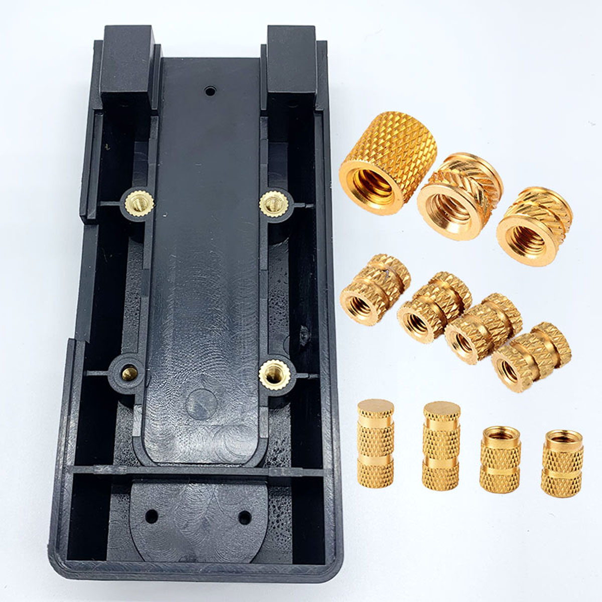
One of the most useful ways to compare threaded insert designs is to understand how the surrounding polymer transfers load to the metal insert.
The following equations are simplified engineering models intended to explain the governing variables.
They should not replace application-specific mechanical testing or supplier validation.
For an insert using circumferential undercut or mechanically engaged geometry, a simplified polymer-shear model can be expressed as:
Fp = π × Dout × Leng × τpoly
Where:
Fp = estimated axial pull-out resistance
Dout = effective outer diameter of the insert engagement geometry (mm)
Leng = effective mechanical engagement length (mm)
τpoly = relevant shear strength of the plastic resin (MPa)
The equation shows an important relationship:
Increasing effective engagement diameter or engagement length increases the theoretical polymer shear area.
However, the equation is simplified.
Actual pull-out performance can also be affected by:
boss diameter
insert geometry
undercut depth
resin anisotropy
glass-fiber orientation
molding conditions
temperature
moisture
creep
stress concentration
installation method
Therefore:
Calculated capacity ≠ guaranteed production performance.
For an OEM program, the final value should be validated through physical testing using the actual resin, insert, boss geometry and production process.
Rotational torque-out resistance depends on the way the insert transfers torque into the surrounding polymer.
A simplified model can be expressed as:
To = ½ × π × (Dout)² × Lknurl × τpoly × μf
Where:
To = estimated torque-out resistance
Dout = effective outer diameter of the mechanically engaged region
Lknurl = effective axial length of the knurled or mechanically engaged region
τpoly = relevant shear strength of the plastic resin
μf = application-dependent mechanical interlock / load-transfer factor
The diameter term is squared in this simplified relationship.
That means insert diameter can have a significant theoretical influence on torque transfer.
However, the μf factor should not be treated as a universal material constant.
It depends on the actual load-transfer mechanism and should be validated against physical testing.
Potential torque-out failure mechanisms include:
Plastic shear around the insert
Local boss cracking
Insert rotation
Knurl pull-through
Resin fracture around the external geometry
Insert deformation
Mating thread failure
This is why torque-out specifications should be based on the actual assembly requirement rather than a theoretical equation alone.
External insert geometry is a critical part of mechanical performance.
Different patterns can emphasize different load-transfer mechanisms.
Straight knurls can provide rotational resistance through mechanical interference with the surrounding polymer.
They may be appropriate where torque-out resistance is a primary requirement.
Diamond knurls provide mechanical engagement in multiple directions.
They can offer a balanced approach for applications requiring both axial and rotational resistance.
Opposing helical patterns can create mechanical resistance against rotation while also providing useful axial engagement.
The best pattern depends on:
resin
installation process
insert diameter
engagement length
required torque
required pull-out load
boss geometry
There is no single knurl pattern that is optimal for every application.
A flange can provide an additional mechanical bearing surface against the surrounding polymer.
This can improve resistance to axial displacement without relying exclusively on cylindrical polymer shear around the insert.
However, the contribution of a flange should be evaluated separately from the simplified cylindrical shear model.
In practical design:
Undercut / Knurl Engagement + Flange Geometry + Boss Structure
should be considered as a combined load-transfer system.
High-volume production problems are rarely caused by the fastener alone.
The most useful troubleshooting approach is to connect:
Failure Mode → Root Cause → Process Variable → Corrective Action
| Failure Mode | Potential Root Cause | Engineering Response |
|---|---|---|
| Resin enters internal threads | Poor insert/core-pin interface, incorrect seating or dimensional variation | Review core-pin fit, insert geometry and critical dimensions |
| Molded-in boss cracks | Differential shrinkage, residual stress, insufficient boss structure | Review resin, boss geometry, insert diameter and molding conditions |
| Post-mold insert does not seat fully | Incorrect hole size, insufficient heat/energy, incorrect insertion parameters | Verify hole dimensions and optimize installation parameters |
| Insert rotates during assembly | Insufficient mechanical engagement or unsuitable knurl geometry | Review knurl pattern, diameter, engagement length and resin |
| Insert tilts | Fixture or probe misalignment | Improve press guidance and alignment |
| Plastic deforms excessively | Excessive installation energy or force | Reduce process energy/force and review boss geometry |
| Pull-out strength is low | Insufficient engagement area or weak surrounding polymer | Increase effective engagement or redesign boss/insert |
| Torque-out strength is low | Insufficient rotational load transfer | Review external geometry and resin compatibility |
| Thread contamination | Poor mold sealing or insert positioning | Review core-pin design, insert tolerance and seating |
| Production variation | Resin/process/insert dimensional variation | Establish critical dimensions and process controls |
Boss cracking deserves particular attention in molded-in applications.
A simplified failure sequence may look like this:
Metal Insert
     │
     ▼
Polymer Shrinkage During Cooling
     │
     ▼
Radial Stress Around Insert
     │
     ▼
Local Stress Concentration
     │
     ▼
Boss Crack
Risk can increase when:
boss walls are too thin
insert diameter is large relative to the boss
resin shrinkage is high
the polymer is crack-sensitive
glass-fiber orientation creates local anisotropy
molding conditions create high residual stress
A common preliminary design practice is to maintain adequate boss wall thickness around the insert, but there is no universal boss-diameter ratio that applies to every polymer and insert geometry.
The final geometry should be validated using the actual resin and production process.
Incomplete seating may occur when:
hole diameter is incorrect
insert diameter is outside tolerance
probe temperature is insufficient
insertion speed is too high
dwell time is too short
polymer does not flow adequately around the external geometry
fixture alignment is poor
The solution is not always “increase temperature.”
Excessive heat can create its own problems:
polymer degradation
excessive deformation
cosmetic defects
dimensional instability
A controlled DOE covering temperature + insertion force + insertion speed + dwell time + hole diameter is often more useful than adjusting one variable independently.
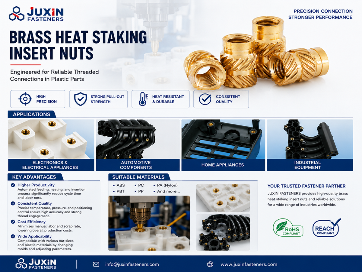
Fastener unit price is only one part of the economics.
A useful TCO model is:
TCO = Fastener Cost + Tooling Cost + Molding Cost + Secondary Assembly Cost + Automation CapEx + Labor + Scrap + Quality Cost + Maintenance + Changeover Cost
Potential advantages:
no separate insert installation step
integrated component after molding
potentially strong mechanical engagement
reduced downstream handling
suitable for certain thermoset applications
Potential disadvantages:
higher mold complexity
insert-loading automation
longer effective molding cycle
higher tooling risk
more difficult hardware changes
insert positioning requirements
Potential advantages:
maximum flexibility in molding architecture
fast base molding cycle
simpler injection mold
easier design revisions
secondary automation can be optimized independently
defective inserts can potentially be isolated during assembly
Potential disadvantages:
secondary equipment
additional floor space
secondary process control
additional handling
installation tooling
labor or automation cost
START
  │
  ▼
What resin is being used?
  │
  ├── Thermoset
  │      │
  │      └── Consider molded-in / mechanical retention
  │
  └── Thermoplastic
         │
         ▼
Are molding cycle time and press utilization critical?
         │
      ┌──┴──┐
      │     │
     YES    NO
      │     │
      ▼     ▼
 Post-Mold  Compare mechanical
 insertion  and tooling economics
      │
      ▼
Is extreme mechanical retention required?
      │
   ┌──┴──┐
   │     │
  YES    NO
   │     │
   ▼     ▼
Evaluate   Post-Mold may
deep       provide better
mechanical flexibility
engagement
   │
   ▼
Compare total installed cost
   │
   ▼
Validate through physical testing
   │
   ▼
FINAL PROCESS SELECTION
Molded-in insertion can be attractive when:
the insert must be integrated during molding
deep external undercuts are required
high mechanical retention is needed
the material cannot be post-melted
downstream assembly should be minimized
automated insert loading can be economically integrated into the molding cell
the mold architecture supports reliable insert positioning
the annual volume justifies the tooling investment
Molded-in insertion is especially worth evaluating when the mechanical requirement cannot be achieved economically through a post-mold process.
Post-mold installation can be attractive when:
maximum injection molding output is important
mold simplicity is a priority
product revisions are expected
multiple insert configurations may be required
secondary automation is easier to implement than in-mold loading
the resin is compatible with heat staking or ultrasonic installation
mold steel exposure to metal inserts should be minimized
production flexibility is important
For large multi-cavity tools, post-mold installation can be particularly attractive because insert feeding and insertion can operate independently of the molding cycle.
However, cavity count alone should never determine the process.
| Process | Main Advantage | Main Risk / Limitation |
|---|---|---|
| Heat staking | Controlled localized thermal installation | Requires thermal parameter control |
| Ultrasonic | Fast automated installation | Sensitive to horn, energy and material parameters |
| Press-fit | No thermal process | Installation force can stress the boss |
| Molded-in | Integrated during molding | Higher tooling and loading complexity |
The selection should be based on the actual polymer and production requirement.
A good threaded-insert RFQ should contain enough information for the supplier to evaluate both the fastener and the manufacturing process.
Include:
thread specification
external diameter
overall length
engagement length
knurl geometry
pilot geometry
flange dimensions
critical tolerances
material
surface treatment
A STEP file is useful for custom insert development and interference analysis.
Do not specify only:
“Nylon”
Instead provide the actual resin grade where possible.
For example:
PA66-GF30
PA66-GF50
PC/ABS
PBT
PEEK
POM
Also specify glass or mineral reinforcement where applicable.
Specify:
Metric or Unified
nominal size
thread pitch
thread class
blind or through thread
functional gauge requirements where applicable
State whether the insert will be:
molded-in
heat staked
ultrasonically installed
press-fit
expansion installed
This information can significantly influence insert geometry.
Possible materials include:
brass
stainless steel
aluminum
The exact alloy should be selected according to:
strength
corrosion resistance
conductivity
weight
environmental requirements
customer specification
Depending on the application, options may include:
plain / cleaned
nickel plating
tin plating
passivation
other specified finishes
If the insert interacts directly with mold core pins, probes or automated feeding equipment, critical dimensions should be clearly identified.
For example, an overall length tolerance around ±0.05 mm may be appropriate for some precision applications, but the actual tolerance should be established according to the mold architecture and supplier manufacturing capability.
High-volume automated assembly may require:
bulk packaging
tray packaging
bowl-feeder-compatible packaging
tape-and-reel
custom carrier packaging
The packaging method should be agreed during automation development rather than after mass production begins.
Depending on the OEM program, the RFQ may require:
material certificates
dimensional inspection reports
RoHS / REACH documentation
PPAP documentation
process capability information
inspection plans
traceability requirements
Specific PPAP submission capability and documentation level should be confirmed with the supplier during sourcing.
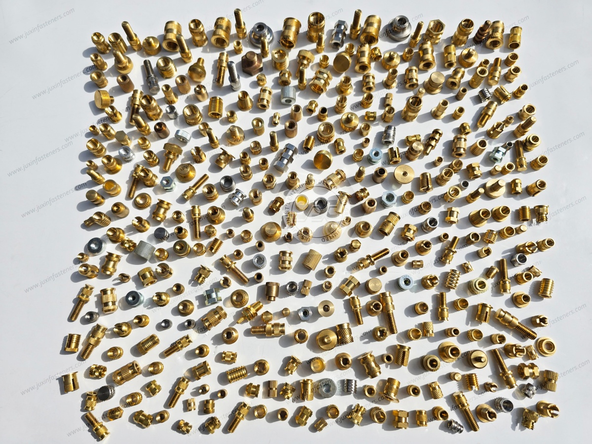
JUXIN FASTENERS supports OEM and industrial customers with threaded inserts and custom fastening components for plastic, metal and engineered-material applications.
The engineering approach is not simply to select an insert from a catalog.
The objective is to match:
Resin + Boss + Insert Geometry + Installation Process + Mechanical Requirement + Production Volume
Depending on the application, JUXIN FASTENERS can supply and develop:
brass threaded inserts
stainless steel threaded inserts
aluminum threaded inserts
heat-staking inserts
ultrasonic-compatible inserts
press-fit inserts
molded-in inserts
flanged inserts
blind threaded inserts
knurled inserts
self-tapping inserts
custom turned threaded bushings
precision CNC-machined inserts
Available configurations can include different:
thread sizes
lengths
external diameters
knurl patterns
undercut geometries
flange configurations
materials
surface treatments
Application-specific availability should be confirmed from the engineering drawing and project requirements.
For OEM projects, the insert should be reviewed together with the plastic component.
Important design inputs include:
boss geometry
hole diameter
wall thickness
resin grade
fiber content
insert dimensions
installation process
pull-out requirement
torque-out requirement
assembly torque
operating temperature
environmental exposure
annual usage
This allows the insert design to be evaluated as part of the complete fastening system.
For high-volume programs, JUXIN FASTENERS can work from:
2D drawings
3D STEP files
customer specifications
samples
application requirements
Manufacturing methods may include:
CNC machining
cold heading
stamping
other application-specific production processes
Material and compliance requirements should be confirmed against the individual customer specification.
Before selecting molded-in or post-mold inserts, an OEM should ideally provide:
Plastic resin grade
Glass-fiber or mineral content
Boss drawing
Hole diameter
Boss outer diameter
Insert thread
Insert length
Required pull-out load
Required torque-out value
Assembly torque
Installation process
Annual volume
Number of inserts per component
Mold cavity count
Operating temperature
Environmental conditions
Required certifications
Packaging requirements
With this information, the supplier can evaluate the fastening system rather than simply quote a nominal insert size.
Molded-in inserts are positioned inside the injection mold before polymer injection.
Post-mold inserts are installed after the plastic component has been molded using heat staking, ultrasonic insertion, press-fit or another secondary process.
Not automatically.
Mechanical performance depends on insert geometry, polymer properties, boss design, engagement area, installation process and environmental conditions.
A properly designed post-mold insert can provide substantial pull-out and torque-out resistance.
There is no universal answer.
Molded-in inserts may eliminate secondary assembly but can increase mold complexity and cycle time.
Post-mold inserts can preserve molding productivity but require a secondary installation process.
The correct decision should be based on total installed cost and required mechanical performance.
They can.
Insert loading and positioning occur as part of the molding process and may increase the effective cycle time.
The actual impact depends on insert quantity, cavity count, automation architecture and mold design.
An illustrative 15–40% increase can occur in some insert-loading architectures, but this is not a universal value.
Yes.
However, loading inserts into 16-, 32- or 64-cavity tools requires careful automation and positioning design.
The relevant question is whether the insert-loading system can maintain the required molding cycle and placement reliability.
Yes, depending on the actual resin grade and component design.
Glass-filled nylon has different thermal and mechanical behavior from unfilled nylon.
Installation temperature, insertion force, hole geometry and boss structure should be validated through testing.
Yes, threaded inserts can be used in PEEK applications, but the high processing temperature and mechanical properties of PEEK require application-specific insert geometry and installation parameters.
Possible causes include differential thermal shrinkage, residual stress, insufficient boss structure, excessive insert diameter, unsuitable resin/insert geometry or environmental stress cracking.
The solution should address the entire system rather than simply changing the insert material.
Potential controls include appropriate core-pin geometry, correct insert seating, controlled insert dimensions and suitable blind-end insert designs.
The exact solution depends on the mold architecture and insert configuration.
At minimum:
drawing
3D CAD file
thread specification
resin grade
insert material
installation method
critical dimensions
mechanical requirements
annual volume
packaging requirements
The more complete the RFQ, the more accurately the supplier can evaluate tooling, manufacturing and TCO.
The choice between molded-in and post-mold threaded inserts should not be reduced to:
“Which insert is stronger?”
The better engineering question is:
“Which fastening architecture delivers the required mechanical performance at the lowest reliable total installed cost?”
For high-volume OEM programs, evaluate the complete system:
Resin
↓
Boss Geometry
↓
Insert Geometry
↓
Installation Method
↓
Molding Cycle
↓
Automation
↓
Tooling CapEx
↓
Scrap Risk
↓
Mechanical Validation
↓
TCO
↓
Production Qualification
The best solution is the one that reliably satisfies the complete application requirement while maintaining manufacturability and economic efficiency.
For custom threaded inserts, molded-in insert programs, heat-staking inserts, ultrasonic inserts or high-volume OEM fastening projects, provide the component drawing, resin specification, installation method and annual volume to the JUXIN FASTENERS engineering team.
Email: info@juxinfasteners.com
Website: www.juxinfasteners.com
Contact Us
Tel.:
+86 020 8621 0320
+86 020 3121 6067
E-mail:
Technical Support:
Navigation
SEND INQUIREY