
Call Us
+86 136 6007 9809
Call Us
+86 136 6007 9809

Sep. 09, 2026
Industrial OEMs designing injection-molded plastic enclosures, automotive components, electrical housings, electronic equipment, appliance assemblies,
and industrial products often face an important manufacturing decision: should a threaded metal insert be placed into the injection mold and encapsulated during molding,
or should the plastic component be molded first and the insert installed afterward?
Both approaches can create a reinforced threaded connection in a thermoplastic component. However, they create different manufacturing requirements and can affect tooling,
production flow, retention mechanism, boss design, dimensional control, installation equipment, and overall assembly cost.
Molded-in inserts are positioned in the mold before or during the molding operation so that the polymer forms around the insert.
Post-molded inserts are installed into an already molded plastic component. Depending on the insert design and host material,
this can include heat-set insertion, ultrasonic insertion, press-fit installation, or another controlled installation process.
The correct decision is not simply "molded-in is stronger" or "post-molded is faster."
The actual result depends on the insert geometry, external retention features, polymer grade, boss design, installation parameters, tooling configuration
, production volume, dimensional requirements, and the required joint performance.
JUXIN FASTENERS supports OEM fastening and custom component requirements involving threaded inserts for plastic, metal inserts, compression limiters,
plastic and nylon fastening components, and related custom parts. This guide explains the engineering and manufacturing trade-offs between molded-in and post-molded inserts so design,
manufacturing, and procurement teams can make a more informed specification decision.
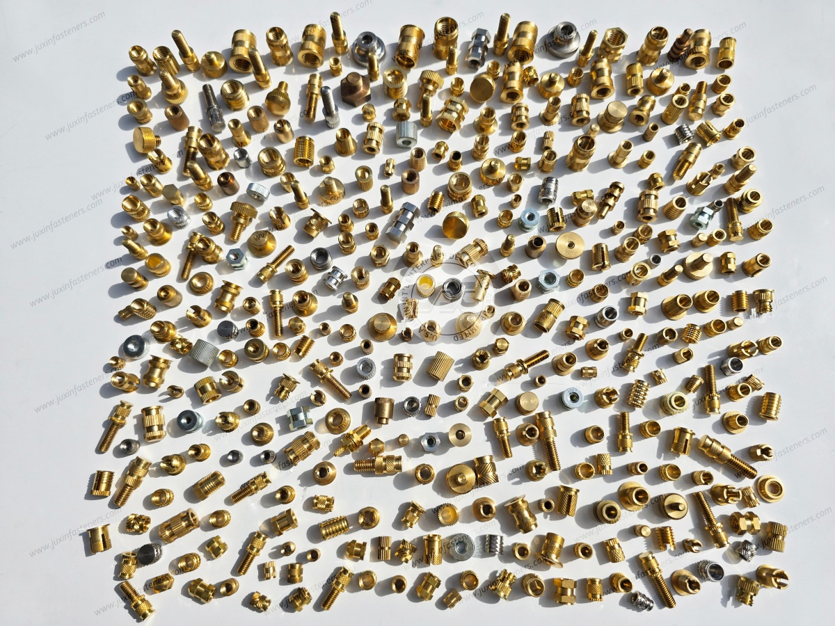
There is no universal winner between molded-in and post-molded threaded inserts.
A practical engineering decision can be approached as follows.
The insert must become an integral part of the molded component during injection molding.
The component geometry and tooling can accommodate reliable insert positioning.
The production process can support insert loading without creating unacceptable cycle-time or handling constraints.
The design benefits from the polymer being molded directly around the insert's external retention features.
The insert location, orientation, and encapsulation can be controlled consistently during molding.
The application requires a reinforced internal thread integrated directly into the molded component.
The injection-molding process should remain separate from insert installation.
Mold tooling complexity or insert-loading operations would be undesirable.
The production process benefits from installing inserts after molded parts have been inspected or sorted.
The housing geometry is suitable for controlled heat-set, ultrasonic, press-fit, or another post-mold installation method.
Insert installation needs to occur at a separate assembly station.
Engineering teams want greater flexibility to modify insert locations or quantities without completely redesigning the molding process.
The final choice should be based on the complete manufacturing system rather than on pull-out strength or cycle time alone.
Choosing when and how to integrate a threaded metal insert into a thermoplastic component introduces several engineering and production variables.
Molded-in inserts must be positioned and retained during the molding process.
Depending on the component and tooling design, inserts may be loaded manually, semi-automatically, or automatically.
This can add handling requirements to each molding cycle.
Post-mold installation separates the molding process from insert installation. This can allow the injection-molding process to operate without loading individual threaded inserts into every molded part.
However, post-mold installation introduces its own assembly operation, equipment requirements, quality controls, and labor or automation costs.
The correct comparison is therefore not simply:
Molded-in = slower
or
Post-molded = faster.
The actual production calculation should compare the entire process:
Molding + Insert Loading + Handling + Inspection
versus
Molding + Post-Mold Insertion + Handling + Inspection
During injection molding, polymer can potentially enter areas around an insert if the mold design, insert retention, sealing, or process conditions allow it.
Internal thread contamination can create additional cleaning, thread verification, or secondary processing requirements.
Appropriate mold design and insert geometry can reduce this risk.
Post-molded insertion avoids placing the threaded component directly into the polymer-flow environment during molding, but it does not automatically mean that the finished thread requires no inspection.
The installation process itself should be controlled to avoid deformation, contamination, incorrect insertion depth, or damage to the internal thread.
A metal insert and a thermoplastic have different thermal and mechanical characteristics.
During injection molding, the polymer flows around the metal insert and subsequently cools.
The resulting component behavior depends on:
Polymer grade
Metal material
Insert geometry
Insert surface features
Boss geometry
Mold temperature
Polymer processing conditions
Cooling behavior
Local residual stresses
Therefore, molded-in inserts should be evaluated together with the surrounding boss and molding process rather than treated as independent hardware.
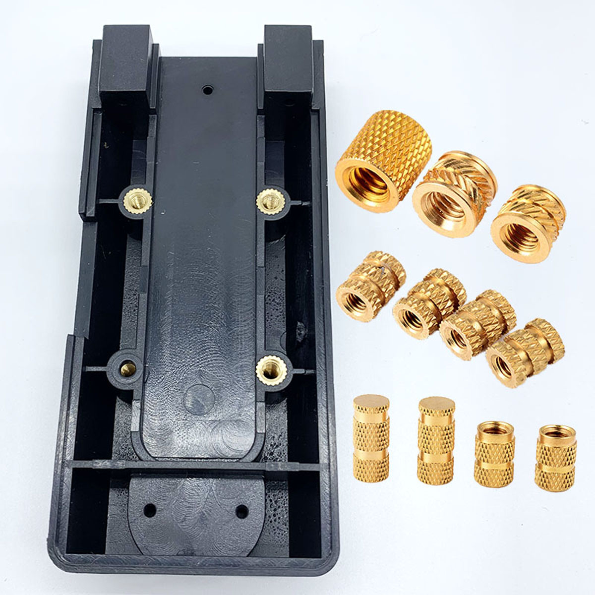
The following comparison provides a practical framework for engineering and manufacturing evaluation.
| Evaluation Parameter | Molded-In Inserts | Post-Molded Inserts |
|---|---|---|
| Integration Method | Insert is positioned in the mold and encapsulated during molding | Insert is installed after the plastic component is molded |
| Retention Mechanism | Polymer encapsulation combined with external features such as knurls, grooves, undercuts, or other geometry | Depends on heat-set reflow, ultrasonic insertion, press-fit, mechanical retention, or the specified installation method |
| Pull-Out Performance | Can provide strong retention when insert geometry, polymer, encapsulation, and molding process are correctly designed | Can also provide strong retention when insert geometry, boss design, hole dimensions, polymer, and installation parameters are correctly controlled |
| Torque-Out Performance | Depends on external insert geometry, polymer engagement, and molded-in process | Depends on external geometry, installation process, hole/boss design, and polymer reflow or mechanical retention |
| Molding Cycle Impact | Insert loading can add handling and cycle-time requirements depending on automation and tooling | Insert installation occurs after molding, separating the two processes |
| Tooling | May require dedicated insert-location and retention features in the mold | Molding tool can potentially avoid insert-retention features, but separate insertion equipment may be required |
| Secondary Operations | Thread protection and inspection may be required if polymer contamination occurs | Post-mold insertion becomes an additional production operation |
| Design Flexibility | Insert locations are closely tied to the mold and molding process | Insert installation can provide more flexibility after molding, depending on part design |
| Production Control | Requires reliable insert positioning during every molding cycle | Requires reliable control of insertion position, depth, force/energy, and process parameters |
| Best Decision Basis | Integrated molding process, geometry, production volume, retention requirements and tooling strategy | Separate assembly process, installation method, flexibility, production flow and total manufacturing cost |
Importantly, the table does not establish universal performance rankings.
A well-designed post-molded insert can outperform a poorly designed molded-in insert, just as a properly designed molded-in system can outperform an unsuitable post-mold installation.
The external geometry of a threaded insert plays a major role in how it interacts with the surrounding polymer.
Common retention features may include:
Knurling
Grooves
Ribs
Undercuts
Flanges
Helical features
Other application-specific external profiles
These features may contribute to resistance against axial movement or rotation.
However, the actual retention mechanism differs between insert types and installation methods.
For example, molded-in inserts can obtain retention from polymer encapsulation around external features.
Heat-set inserts depend on controlled polymer reflow around the external geometry.
Ultrasonic inserts depend on controlled ultrasonic energy and mechanical insertion to establish the required polymer-to-insert interface.
Therefore, the insert geometry should be designed together with the installation process.
Regardless of installation method, the surrounding polymer is a critical part of the fastening system.
Different thermoplastics respond differently to molding and post-mold insertion.
Potential host materials include:
PA6
PA66
Glass-filled PA66
PC/ABS
PBT
ABS
Other engineering thermoplastics
The actual resin grade matters.
A generic statement such as "nylon" or "plastic" may not provide enough information for engineering selection because reinforcement, moisture condition,
additives, processing history, and temperature can change material behavior.
PA6 and PA66 can be used in many industrial and electronic applications.
Their moisture absorption and temperature-dependent mechanical behavior should be considered when evaluating insert retention and dimensional stability.
Glass-filled grades may behave differently from unfilled grades and may require different installation-process evaluation.
Glass-filled materials can present different insertion behavior because the reinforcement changes the local polymer structure and processing response.
Post-mold thermal or ultrasonic insertion may still be possible, but the insert design, boss geometry, hole condition, process parameters, and installation equipment should be validated for the specific resin grade.
PC/ABS and PBT are used in many housings, electrical components, automotive parts, and industrial assemblies.
The appropriate insertion method depends on the actual resin grade, component geometry, insert design, and production process.
The host material should therefore be specified as accurately as possible in the engineering drawing or RFQ.
The boss is not simply a holder for the insert.
It forms part of the mechanical system.
Important design variables include:
Boss outside diameter
Hole diameter
Boss wall thickness
Boss height
Insert length
Insert outside diameter
Distance from nearby edges
Rib configuration
Draft and molding conditions
Local material thickness
For post-molded insertion, the pre-molded hole may be designed specifically for the selected installation process.
For molded-in inserts, the insert position and surrounding polymer flow must be considered during mold design.
A supplier should therefore review the insert and plastic component together whenever possible.
Molded-in installation can be highly effective when the insert is properly integrated into the injection-molding process.
However, several factors should be evaluated.
The insert must remain correctly positioned during polymer injection.
Depending on the tooling design, retaining pins, cores, fixtures, magnetic retention, mechanical retention, or automated loading systems may be used.
The appropriate method depends on the insert material, geometry, orientation, mold design, and production process.
The mold should allow polymer to flow around the insert as intended.
Poorly designed geometry can contribute to:
Local voids
Uneven encapsulation
Flow-related defects
Sink marks
Residual stress
Dimensional variation
Actual defect risks depend on the part geometry and molding process.
External knurling, grooves, ribs, or undercuts may be selected to create the desired mechanical interaction with the polymer.
The correct feature should be evaluated according to the required retention mechanism and molding process.
Post-molded installation provides a different manufacturing architecture.
Instead of placing the insert into the mold, the plastic component is molded first and the insert is installed afterward.
Heat-set brass inserts are commonly used in thermoplastic housings and other molded plastic components.
During installation, controlled heat softens the surrounding polymer so that the insert can be positioned into the prepared hole.
After the polymer cools, the insert becomes mechanically retained within the surrounding material.
The actual insertion temperature, installation depth, tooling, and process window should be established for the specific insert and polymer system rather than treated as universal values.
Ultrasonic inserts use controlled ultrasonic energy during installation.
The process can be suitable for certain thermoplastic assemblies where production equipment and component geometry support the method.
As with heat-set insertion, process parameters must be developed for the specific insert, polymer, boss geometry, and production equipment.
Some post-molded inserts may use mechanical retention or press-fit installation.
This approach can avoid thermal reflow, but the hole diameter, interference condition, polymer properties, insertion force, boss strength, and long-term retention requirements must be evaluated.
Not every threaded insert is suitable for every installation method.
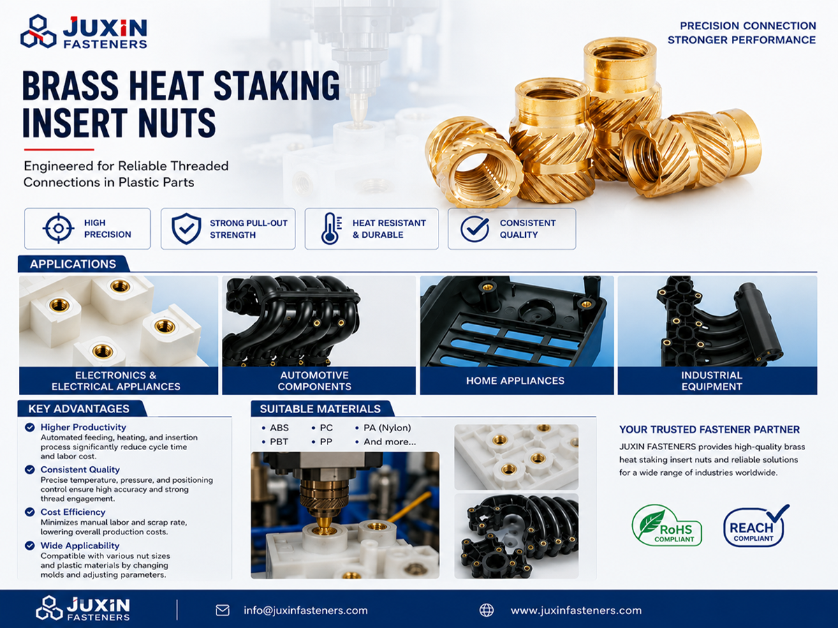
Molded-in inserts may be attractive when:
The insert position is stable and unlikely to change during product development.
The mold can accommodate reliable insert positioning.
The manufacturing process can efficiently load and retain the inserts.
The insert geometry is specifically designed for molded encapsulation.
The production volume and automation strategy justify the tooling and handling requirements.
The integrated molding process provides the desired dimensional and retention performance.
Molded-in inserts may also be appropriate when the insert must become an integral part of the component from the beginning of the molding process.
Post-molded inserts may be attractive when:
Injection molding should remain a high-throughput standalone process.
Insert installation can be automated or efficiently controlled downstream.
The component design supports reliable post-mold insertion.
The project requires greater flexibility during product development.
The insertion process can be validated for the selected polymer and boss design.
The cost of additional assembly equipment is justified by the overall production strategy.
Post-molded installation can also simplify certain tooling strategies, but this should be evaluated against the added insertion operation.
Molded-in and post-molded threaded inserts are not the answer to every plastic fastening problem.
An insert may not be necessary when:
The plastic can directly accommodate the required fastening function.
The required assembly load is low.
A plastic screw or nylon screw provides an adequate fastening solution.
A plastic nut or nylon nut can satisfy the joint requirements.
The primary requirement is spacing rather than thread reinforcement.
The assembly needs an electrical or dimensional isolation component rather than a threaded insert.
For example, an electronic assembly may need:
Plastic flat washers
Nylon washers
Shoulder washers
Insulating cup washers
Cup washers
Plastic spacers
Nylon spacers
PCB spacers
Threaded standoffs
Male-to-female standoffs
Female-to-female standoffs
rather than a reinforced threaded insert.
Similarly, where the main concern is maintaining a defined axial compression path through a plastic component, a compression limiter may be more appropriate than a threaded insert.
The engineering decision should therefore begin with the actual failure mode and fastening requirement.
Threaded inserts should be considered as part of the complete fastening system.
A plastic enclosure, PCB assembly, automotive component, electrical cabinet, or industrial housing may contain several different fastening interfaces.
These may include:
Plastic screws
Nylon screws
Plastic bolts
Nylon bolts
Plastic machine screws
Nylon machine screws
Plastic nuts
Nylon nuts
Custom plastic nuts
Nylon hex nuts
Plastic flat washers
Nylon washers
Shoulder washers
Insulating cup washers
Cup washers
Plastic spacers
Nylon spacers
Industrial plastic spacers
PCB spacers
Threaded standoffs
Male-to-female standoffs
Female-to-female standoffs
Threaded inserts for plastic
Heat-set inserts
Heat-set brass inserts
Ultrasonic inserts
Brass thread inserts
Molded-in inserts
Expansion inserts
Compression limiters
Custom metal inserts for plastic
Custom polymer fastening components
These products perform different functions and should not be treated as interchangeable.
For example:
Threaded insert: reinforces or provides an internal thread in plastic.
Compression limiter: establishes a defined axial load path through a plastic component.
Plastic spacer: creates separation or dimensional spacing.
Standoff: creates a defined mounting distance and may incorporate internal or external threads.
Shoulder washer: can provide spacing, insulation, or controlled positioning around a fastener depending on the design.
This functional distinction is important for both engineering design and procurement.
Electronic housings and electrical enclosures are common applications for threaded inserts.
Typical fastening architectures may involve:
Plastic housings
PCB mounting structures
Cover assemblies
Mounting brackets
Cable-management components
Internal support structures
Shielding-related components
An enclosure may use molded-in inserts at permanent structural mounting points while using post-molded inserts in another component.
It may also combine inserts with nylon washers, shoulder washers, spacers, and standoffs.
The correct choice depends on the function of each fastening point.
Molded-in and post-molded inserts can be considered in applications including:
Potential applications include:
Interior plastic modules
Electrical housings
Battery-related plastic components
Mounting brackets
Covers
Sensor housings
Electronic control housings
For demanding automotive and EV applications, the actual temperature, vibration, chemical exposure, mechanical loading, material grade, and validation requirements should be defined by the OEM.
Potential applications include:
Electrical cabinets
Power distribution housings
Control boxes
Junction boxes
Industrial electrical enclosures
Power electronics housings
The insert and polymer combination should be evaluated against the electrical, mechanical, environmental, and manufacturing requirements of the specific assembly.

Telecommunications equipment, base stations, antennas, and electronic cabinets may use reinforced threaded interfaces within plastic or composite components.
The design should consider environmental exposure, vibration, installation method, and the complete fastening architecture.
Industrial machinery may contain plastic covers, control housings, guards, brackets, panels, and electronic modules.
Molded-in or post-molded inserts can provide threaded interfaces where direct polymer threads are not suitable for the intended assembly.
A complete RFQ allows the supplier to evaluate both the component and the intended manufacturing process.
Procurement teams should ideally provide:
Specify the preferred or proposed type:
Molded-in threaded insert
Heat-set brass insert
Heat-set insert
Ultrasonic insert
Press-fit insert
Expansion insert
Other custom metal insert for plastic
If the installation method is not yet decided, state the engineering requirement and ask the supplier to evaluate the available options.
Include:
Metric thread
UNC
UNF
Thread diameter
Pitch
Thread length
Internal thread requirement
Do not assume that a generic "standard thread" provides enough information for production.
Provide:
Insert length
Outside diameter
Thread dimensions
External retention geometry
Flange dimensions where applicable
Critical tolerances
Surface requirements
The plastic component drawing should also be provided when the insert is designed for a specific boss.
Specify the actual material and grade where available:
PA6
PA66
Glass-filled PA66
PC/ABS
PBT
ABS
Other engineering thermoplastic
State whether the project currently requires:
Molded-in installation
Heat-set installation
Ultrasonic installation
Press-fit installation
Another post-mold process
If the method is still under evaluation, provide the production constraints so the supplier can participate in the engineering comparison.
Include, where relevant:
Mechanical loading
Assembly frequency
Temperature exposure
Thermal cycling
Vibration
Moisture
Chemical exposure
Required dimensional stability
Service environment
Provide:
Prototype quantity
Initial production quantity
Annual volume
Forecast
Packaging requirements
Labeling
Inspection requirements
Delivery requirements
Multi-SKU BOM information
Prototype validation should evaluate more than whether the insert can be installed.
Engineers should consider:
Insert position
Insertion depth
Boss deformation
Thread condition
Retention behavior
Assembly repeatability
Visual quality
Dimensional stability
Installation equipment consistency
Host material condition
Environmental exposure where relevant
For molded-in inserts, the validation should include the molding process and insert positioning.
For post-molded inserts, validation should include the complete insertion process and its process controls.
Where the application is mechanically demanding, the actual joint should be tested under representative conditions rather than relying only on generic catalog performance.
The lowest component price does not necessarily represent the lowest total manufacturing cost.
Procurement teams should consider the complete cost structure.
Potential factors include:
Insert component cost
Mold modification or tooling cost
Insert loading equipment
Manual loading labor
Automation
Additional cycle time
Mold maintenance
Inspection
Scrap or rework
Potential factors include:
Insert component cost
Insertion equipment
Heat-staking or ultrasonic equipment where applicable
Operator or automation cost
Process validation
Additional handling
Inspection
Maintenance
Scrap or rework
The appropriate comparison is therefore total landed manufacturing cost, not simply the price of the threaded insert.
A capable OEM supplier should be able to discuss more than the unit price.
Procurement teams should evaluate whether the supplier can support:
Can the supplier review the insert drawing together with the plastic boss and identify important dimensional or manufacturing considerations?
Can the supplier manufacture the specified metal material and provide appropriate material documentation when required by the project?
Can the supplier consistently manufacture knurls, grooves, undercuts, flanges, and other external retention features?
Can the supplier control the internal thread according to the approved drawing and applicable thread specification?
Can the supplier discuss molded-in, heat-set, ultrasonic, press-fit, or other appropriate installation approaches without claiming that one process is universally superior?
Can the supplier support samples, drawing review, prototype evaluation, engineering changes, and production transition?
For OEM customers with multiple plastic fastening requirements, can the supplier also support:
Compression limiters
Plastic nuts
Nylon hex nuts
Plastic flat washers
Shoulder washers
Insulating cup washers
Plastic spacers
Nylon spacers
PCB spacers
Threaded standoffs
Male-to-female standoffs
Female-to-female standoffs
Plastic screws
Nylon screws
Plastic bolts
Nylon bolts
Other custom polymer fastening components
This can reduce supplier interfaces when the customer has a large plastic fastening BOM.
Neither method should be considered universally stronger.
Molded-in inserts can achieve strong retention when the insert geometry, polymer encapsulation, boss design, and molding process are properly engineered.
Post-molded inserts can also provide strong retention when the insert geometry, host material, boss dimensions, hole design, and installation process are correctly controlled.
Actual pull-out and torque-out performance must be evaluated for the specific insert and assembly.
Post-molded heat-set inserts allow the plastic component to be molded without loading individual threaded inserts into the mold.
The inserts can then be installed in a separate production step.
This can provide manufacturing flexibility, but the additional insertion operation and equipment must be included in the total production-cost analysis.
Thread contamination or polymer flash can occur if the mold, insert positioning, sealing, or process conditions allow polymer to enter areas that should remain open.
Appropriate mold and insert design can reduce this risk.
Thread inspection and cleaning requirements should still be established for the production process.
They can be used in some glass-filled thermoplastic applications.
However, the specific resin grade, reinforcement level, boss geometry, hole dimensions, insert design, and installation process should be evaluated and validated.
A generic insertion temperature or force should not be assumed to apply to every glass-filled material.
No.
A heat-set brass insert is generally installed after the plastic component has been molded through a controlled thermal insertion process.
A molded-in insert is positioned during the injection-molding process and becomes integrated as the polymer is molded around it.
Both can provide reinforced internal threads, but their manufacturing processes are different.
Not automatically.
Ultrasonic insertion and heat-set insertion use different process mechanisms.
The appropriate method depends on the insert design, polymer, boss geometry, production equipment, quality requirements, and manufacturing economics.
No.
High mechanical loading does not automatically determine the manufacturing method.
The engineer should evaluate the required joint performance, retention mechanism, polymer, insert geometry, boss design, molding process, installation process, production volume, and validation requirements.
Thread and dimensional requirements should be defined according to the customer's drawing and applicable specification.
Where an ISO, DIN, ASME, ANSI, or other standard is specified for a particular characteristic, the supplier should manufacture and inspect that characteristic according to the agreed requirement.
A custom threaded insert should not be described as automatically conforming to every international standard simply because it is a threaded metal component.
Provide the 2D drawing, 3D CAD model, thread specification, insert dimensions, external retention geometry, host polymer and grade,
preferred installation method, application conditions, production volume, inspection requirements, and packaging requirements.
If the molded-in versus post-molded decision has not yet been finalized, provide the plastic component drawing and manufacturing constraints so the supplier can help evaluate the alternatives.
Before production release, engineering teams should verify the complete insert and plastic assembly.
Material
Outside diameter
Overall length
Internal thread
Thread tolerance
External retention geometry
Surface treatment where specified
Critical dimensional tolerances
Polymer grade
Boss diameter
Boss height
Hole diameter
Wall thickness
Edge distance
Rib geometry
Relevant molding dimensions
Molded-in or post-molded method
Insert positioning
Insertion depth
Installation equipment
Process controls
Inspection method
Handling requirements
Mating fastener
Fastener material
Washer arrangement
Assembly method
Required joint behavior
Environmental conditions
The key point is simple:
Do not validate only the insert. Validate the insert, plastic boss, installation process, fastener, and complete joint as one system.
Choosing molded-in vs. post-molded inserts is a manufacturing and engineering decision, not simply a catalog-product decision.
The appropriate approach depends on the host polymer, boss design, insert geometry, retention mechanism, molding process,
post-mold installation process, production volume, tooling strategy, assembly requirements, and total manufacturing cost.
JUXIN FASTENERS supports OEM requirements for:
Molded-in threaded inserts
Heat-set brass inserts
Heat-set inserts for plastic
Ultrasonic inserts
Brass thread inserts
Expansion inserts
Compression limiters
Custom metal inserts for plastic
Plastic and nylon fastening components
Custom polymer fastening components
For complete plastic fastening BOMs, related products can also include plastic screws, nylon screws, plastic bolts, nylon bolts, plastic machine screws,
nylon machine screws, plastic nuts, nylon nuts, custom plastic nuts, nylon hex nuts, nylon washers, plastic flat washers, shoulder washers,
insulating cup washers, plastic spacers, nylon spacers, industrial plastic spacers, PCB spacers, threaded standoffs, male-to-female standoffs, and female-to-female standoffs.
Send your 2D drawing, 3D CAD file, host plastic material and grade, insert requirements, preferred installation method, application conditions, production volume, and quality requirements to:
The JUXIN FASTENERS engineering and sourcing team can review your requirements and discuss the appropriate insert configuration, manufacturing approach, prototype requirements, and OEM quotation.
Contact Us
Tel.:
+86 020 8621 0320
+86 020 3121 6067
E-mail:
Technical Support:
Navigation
SEND INQUIREY


