
Call Us
+86 136 6007 9809
Call Us
+86 136 6007 9809

Aug. 11, 2026
Why does an O-ring leak even when its nominal size and material appear correct?
Because an O-ring is only one component of a sealing system.
Successful sealing depends on the interaction between:
O-Ring Material + Cross-Section + Groove Geometry + Squeeze + Stretch + Clearance + Pressure + Temperature + Fluid + Surface Condition + Motion + Installation
A seal can therefore fail even when the O-ring itself conforms dimensionally to the drawing.
This distinction is especially important in:
Hydraulic equipment
Pneumatic systems
Pumps and valves
Industrial machinery
Automotive components
HVAC equipment
Fluid-control equipment
Food-service equipment
Medical equipment
Electrical and electronic enclosures
The five most useful failure categories for engineering diagnosis are:
Incorrect squeeze or compression
Elastomer and fluid/environment incompatibility
Incorrect gland or groove design
Extrusion under pressure
Installation damage
But the most important engineering principle is:
O-Ring Failure ≠ O-Ring Defect.
Before changing suppliers or specifying a "better rubber," engineers should identify the actual failure mechanism.
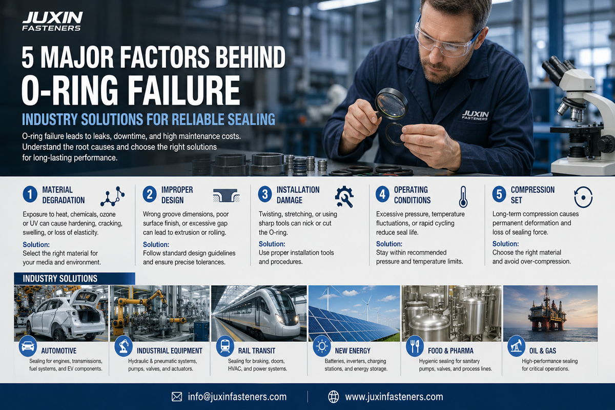
Most O-ring failures can be traced to one or more interactions between the seal, gland and operating environment.
Typical causes include:
Too little squeeze
Excessive squeeze
Compression set
Incorrect material
Chemical attack
Swelling
Hardening
Thermal degradation
Incorrect groove dimensions
Excessive extrusion gap
Pressure cycling
Surface damage
Abrasion
Twisting
Cutting during installation
Contamination
Poor lubrication
Dynamic wear
This means the correct diagnostic question is not:
"Which O-ring material is best?"
It is:
"What failure mechanism is occurring in this specific sealing system?"
ISO 3601 is an important international framework for O-rings.
Depending on the applicable part, the ISO 3601 series addresses areas including:
O-ring dimensions
Housing dimensions
Quality acceptance criteria
ISO 1629 provides nomenclature for rubbers and latices and is useful when identifying elastomer families such as:
NBR
FKM
EPDM
VMQ
But standards should not be used to imply application qualification.
An O-ring can meet dimensional requirements and still fail because the selected elastomer is incompatible with the fluid, temperature or motion.
Therefore:
Standard Compliance ≠ Application Qualification.
An O-ring creates sealing contact through controlled deformation when installed in its gland.
This deformation is often described as squeeze.
If squeeze is insufficient, the sealing contact may not be adequate for the application.
If squeeze is excessive, the elastomer may experience excessive deformation, friction, heat or accelerated compression-set behavior.
The important principle is:
More O-Ring Compression ≠ Better Sealing.
Possible symptoms include:
Leakage at low pressure
Leakage before pressure energizes the seal
Poor sealing after dimensional variation
Sensitivity to thermal contraction
Inconsistent assembly performance
Potential causes include:
Groove too deep
Incorrect O-ring cross-section
Excessive dimensional tolerance
Incorrect component geometry
O-ring stretch reducing cross-section
Assembly distortion
The correct solution is not automatically a larger O-ring.
Changing cross-section without reviewing gland geometry can create a new failure mode.
Excessive squeeze can contribute to:
High assembly force
Increased friction
Dynamic wear
Heat generation
Permanent deformation
Accelerated compression set
O-ring damage during assembly
In dynamic applications, excessive contact pressure can be particularly problematic because the seal must both contain the fluid and move against a mating surface.
Generic design guides often publish ranges for static and dynamic O-ring squeeze.
These can be useful starting references, but they should not be converted into universal rules such as:
Static seals always require X% squeeze.
Actual design depends on:
O-ring cross-section
Elastomer hardness
Material
Temperature
Pressure
Groove type
Static or dynamic service
Stretch
Swell
Tolerances
Manufacturer recommendations
Use the applicable ISO 3601 housing guidance, elastomer supplier data and validated application requirements.
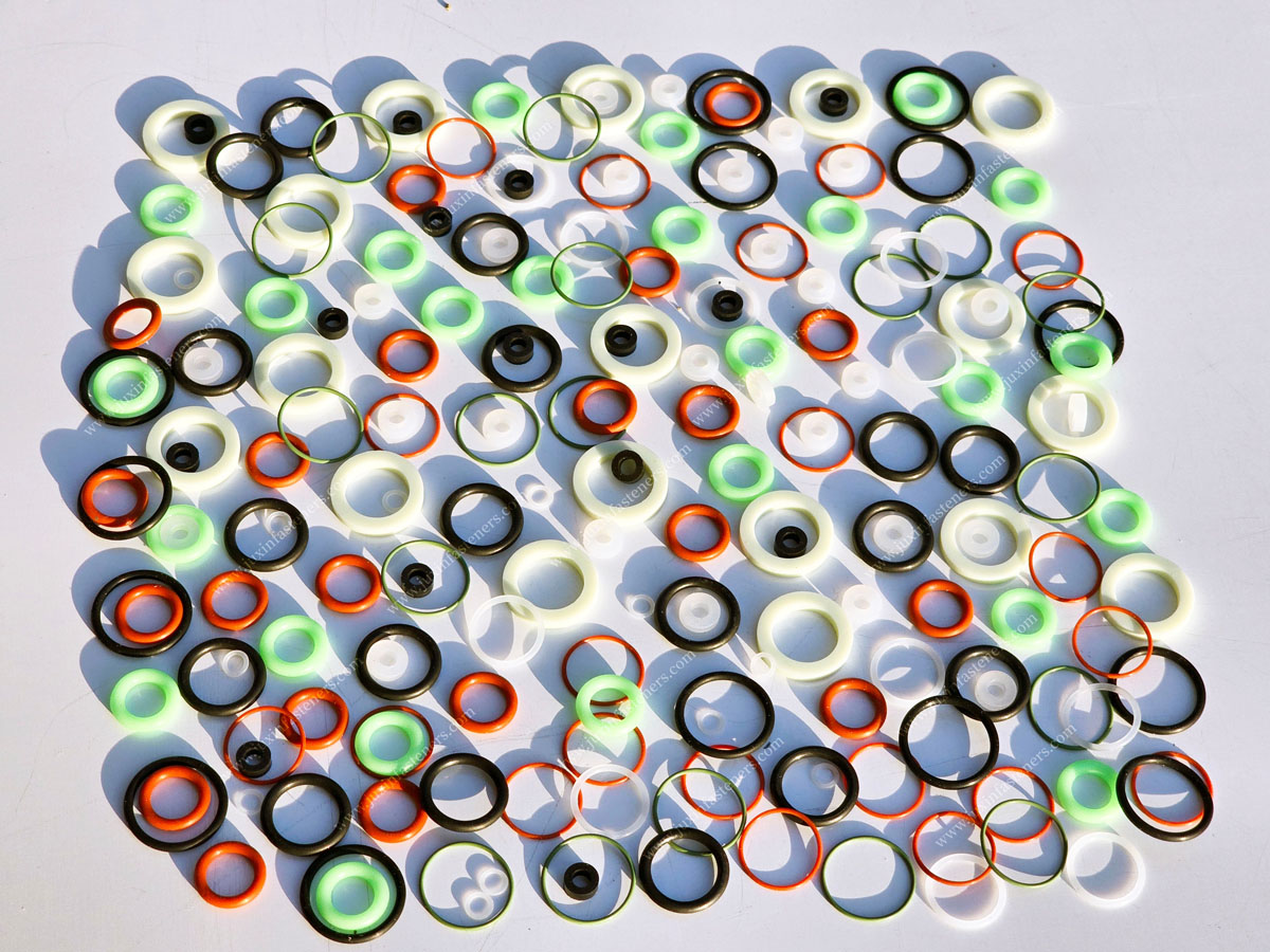
Compression set describes the tendency of an elastomer to retain permanent deformation after prolonged compression.
It can be influenced by:
Elastomer formulation
Temperature
Time
Compression
Fluid exposure
Aging
A seal that has lost elastic recovery may no longer maintain sufficient contact with the sealing surfaces.
But:
Compression Set ≠ One Universal O-Ring Life Expectancy.
Two seals made from the same broad polymer family can behave differently because elastomer compounds are not defined only by polymer name.
Material selection is one of the most misunderstood parts of O-ring engineering.
A material should not be selected from a simplistic rule such as:
Oil → NBR
High temperature → FKM
Water → EPDM
Low temperature → silicone
Those associations can be useful starting points, but the actual application requires more information.
Material compatibility depends on:
Exact fluid
Fluid concentration
Additives
Temperature
Pressure
Exposure duration
Gas or liquid phase
Dynamic or static service
Required mechanical properties
Therefore:
Elastomer Family ≠ Complete Material Specification.
NBR is commonly considered for applications involving many petroleum-based oils and fuels.
Potential advantages can include:
Good oil resistance for suitable media
Useful mechanical properties
Broad industrial availability
Cost-effective performance in many applications
But compatibility depends on the actual compound and medium.
NBR should not be described simply as "oil-proof."
Potential limitations can include certain:
High-temperature environments
Ozone exposure
Weathering conditions
Chemicals
Specialized fluids
The exact compound must be evaluated.
FKM materials are often selected for demanding temperature and chemical environments.
Potential applications include:
Automotive systems
Fuel systems
Industrial equipment
Chemical processing
Selected high-temperature applications
But:
FKM ≠ Universal Chemical Resistance.
Different FKM formulations can have different resistance to:
Amines
Steam
Hot water
Acids
Fuels
Specialty chemicals
Do not specify "FKM" alone when chemical compatibility is critical.
EPDM can be useful in selected applications involving:
Water
Weather exposure
Ozone
Some steam conditions
Selected chemicals
But EPDM is not universally compatible with petroleum-based oils and fuels.
Again, the exact compound and fluid must be checked.
VMQ silicone can provide useful performance across selected temperature ranges and may offer good flexibility at low temperatures.
However, mechanical properties such as:
Tear resistance
Abrasion resistance
Wear behavior
can limit its use in some dynamic sealing applications.
It is therefore unsafe to conclude:
Wide Temperature Range = Best O-Ring Material.
Temperature capability is only one selection variable.
Some OEM applications require specialized materials such as fluorosilicone (FVMQ), particularly where the combination of fuel resistance and low-temperature flexibility is important.
JUXIN FASTENERS has supported drawing-based fastener projects involving sealing elements such as FVMQ O-rings integrated with threaded components.
In such applications, the O-ring cannot be sourced independently from the fastener geometry.
The complete system may involve:
Screw Geometry + O-Ring Material + Groove/Retention Feature + Compression + Mating Surface + Installation
This creates a different sourcing requirement from purchasing a standard loose O-ring.
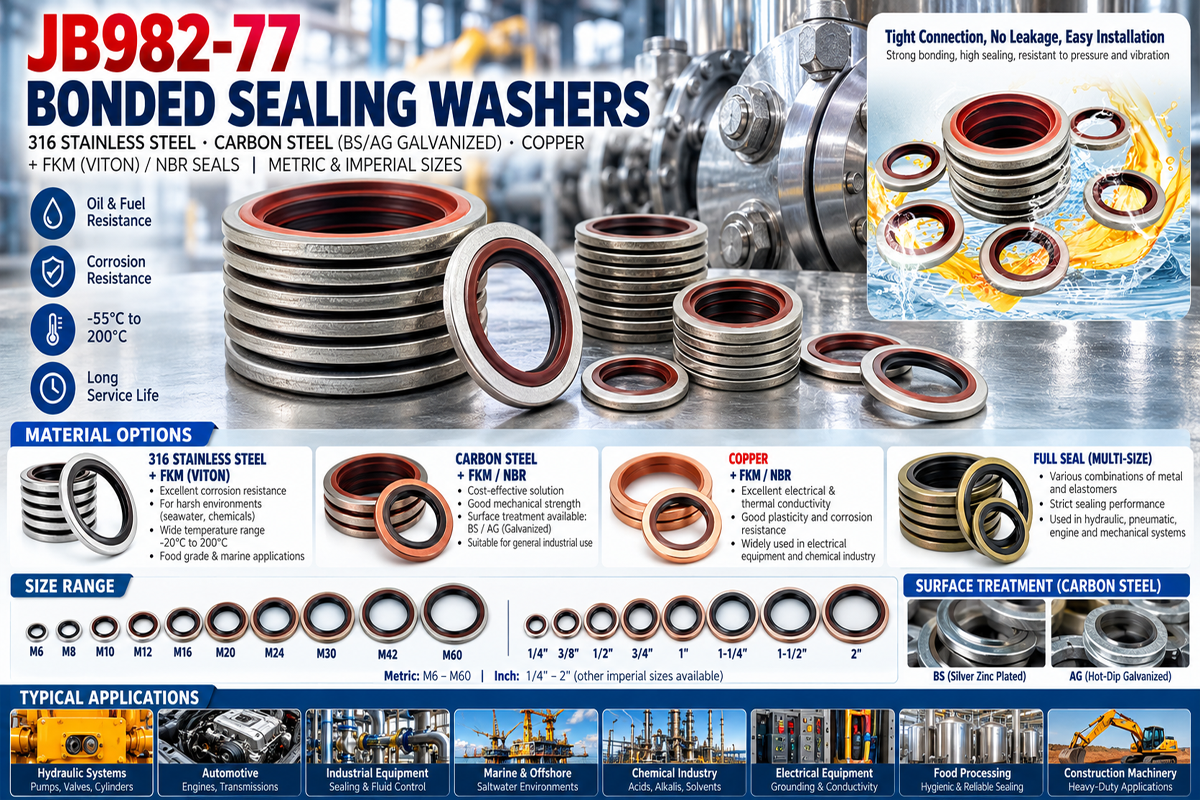
If an O-ring becomes larger after service, possible causes include:
Fluid absorption
Chemical incompatibility
Compound interaction
Temperature effects
Swelling can change:
Seal volume
Friction
Groove fill
Mechanical properties
Assembly behavior
But a swollen seal does not automatically prove poor manufacturing quality.
The investigation should compare:
Original Compound + Fluid + Temperature + Exposure Time + Physical Change
An O-ring that becomes hard or cracked may indicate:
Thermal aging
Oxidation
Chemical degradation
Ozone exposure
Incompatible environment
The location and morphology of damage can provide useful diagnostic information.
For example, surface cracking is a different clue from a seal showing severe extrusion damage at the clearance gap.
Failure appearance should therefore be treated as evidence—not merely as a reason to replace the O-ring.
For critical OEM applications, an RFQ should preferably define more than:
NBR O-Ring
or:
FKM O-Ring
Depending on the application, procurement may need:
Elastomer family
Compound or specification
Hardness
Color if functional
Temperature requirement
Fluid compatibility
Dimensional standard
Quality acceptance requirement
Customer-specific material requirements
This improves second-source qualification.
An excellent O-ring installed in a poor gland can still fail.
Groove design influences:
Squeeze
Groove fill
Stretch
Seal movement
Extrusion gap
Installation
Dynamic friction
ISO 3601-2 provides housing dimensions for general applications within its scope.
The important principle is:
O-Ring Size ≠ Complete Seal Design.
The gland must be designed as part of the sealing system.
Groove depth influences the installed compression of the O-ring.
If the groove is too deep:
Squeeze may be insufficient
Initial sealing may be unreliable
If the groove is too shallow:
Squeeze may become excessive
Assembly force may rise
Seal damage may occur
But nominal groove depth alone is insufficient.
Engineers must perform a tolerance analysis using:
Maximum/minimum O-ring cross-section
Groove depth tolerance
Mating-component tolerance
Thermal dimensional changes where relevant
The O-ring needs enough gland volume to accommodate:
Initial deformation
Thermal expansion
Fluid-induced swell
Manufacturing variation
An overfilled groove can leave insufficient space for elastomer displacement.
A very large groove may permit excessive movement in certain applications.
Therefore:
Groove Width ≠ Arbitrary Clearance.
Groove dimensions should come from the sealing architecture and applicable design guidance.
Rules such as:
Groove width = 1.3 × O-ring cross-section
may appear convenient, but they should not be treated as universal engineering requirements.
Static axial seals, static radial seals, reciprocating seals and rotary applications can require different gland designs.
Use application-specific design guidance rather than one multiplier across every sealing system.
The mating surface interacts directly with the elastomer.
Surface condition can influence:
Leakage
Friction
Lubrication retention
Wear
Seal life
But one universal roughness value should not be assigned to every O-ring application.
Requirements can differ between:
Static sealing surfaces
Dynamic rods
Dynamic bores
Groove surfaces
The manufacturing process and surface texture direction may also matter.
Ra Value Alone ≠ Complete Surface Specification.
Sharp features can damage an O-ring during installation.
Risk areas include:
Thread crests
Cross holes
Keyways
Machined edges
Ports
Steps
A seal may be cut during assembly and still appear to function initially.
Leakage can then develop later.
This creates an important quality lesson:
Field Leakage ≠ Field-Originated Damage.
The failure may have started during assembly.
Extrusion occurs when pressure forces elastomer into the clearance gap between mating components.
Repeated extrusion can lead to:
Nibbling
Shearing
Edge damage
Progressive material loss
Leakage
The risk depends on more than system pressure.
Important variables include:
Pressure
Pressure cycling
Extrusion gap
O-ring hardness
Material
Temperature
Seal geometry
Direction of pressure
Component deformation
Therefore, statements such as:
"Above 10 MPa, always use a backup ring"
are too simplistic.
There is no universal pressure threshold independent of clearance, hardness, temperature and seal design.
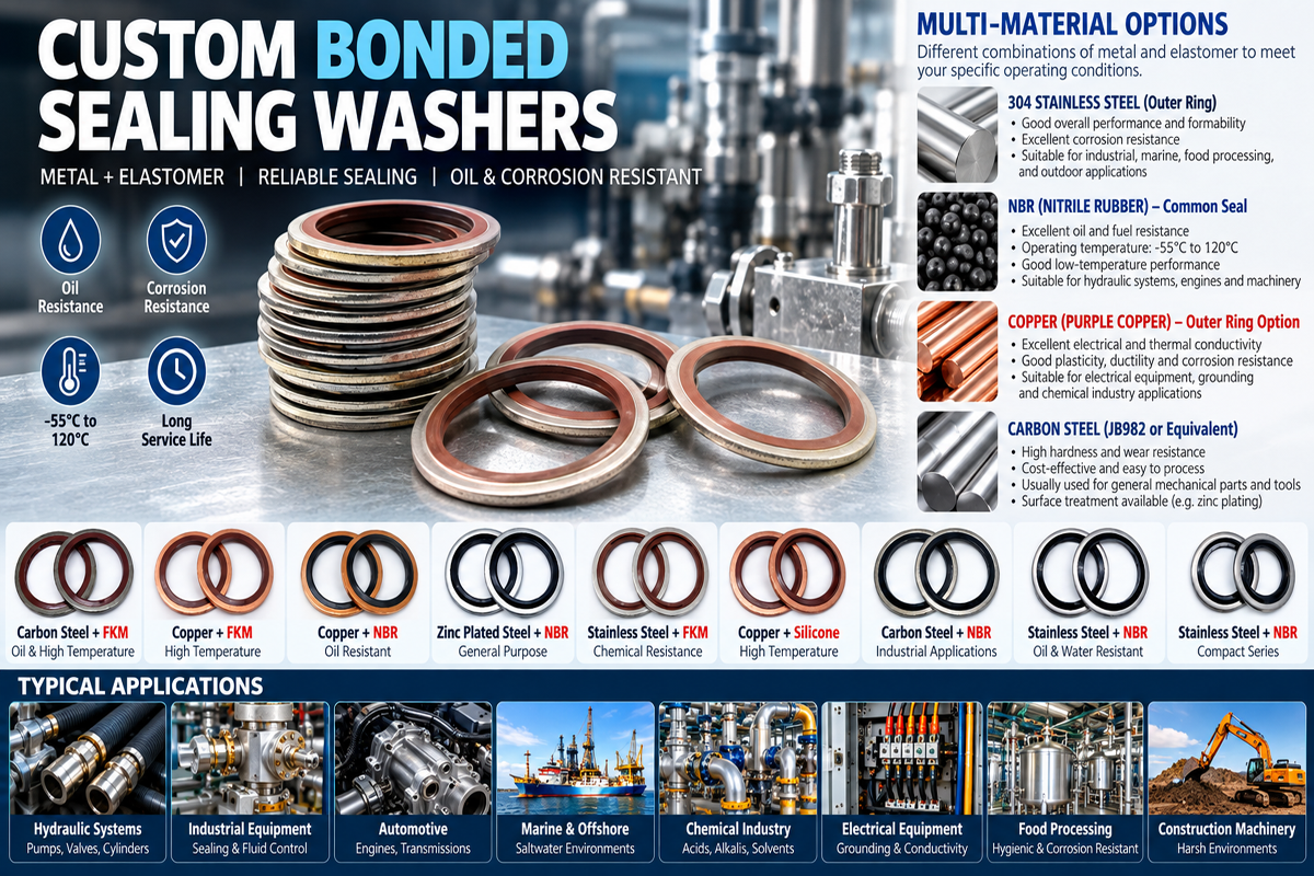
Consider two systems operating at the same pressure.
System A has:
Small controlled extrusion clearance
Rigid components
Suitable elastomer
System B has:
Larger clearance
Component deflection
Elevated temperature
Softer elastomer
The extrusion risk can be very different.
Therefore:
Same Pressure ≠ Same Extrusion Risk.
This is a valuable diagnostic point for hydraulic and pneumatic engineers.
Back-up rings can be used to reduce extrusion risk in appropriate high-pressure sealing systems.
PTFE and other engineered materials may be selected depending on the application.
The arrangement depends on:
Pressure direction
Groove design
Seal movement
Temperature
Fluid
Clearance
A back-up ring should not simply be added without reviewing the gland.
Back-Up Ring ≠ Automatic High-Pressure Qualification.
Where pressure acts primarily from one direction, a back-up ring may be positioned on the low-pressure side according to the seal design.
Where pressure can reverse, the sealing architecture may require anti-extrusion support on both sides.
The final arrangement must follow the actual pressure cycle and gland design.
A harder elastomer may improve resistance to extrusion in some applications.
But higher hardness can also influence:
Conformability
Installation
Low-pressure sealing
Friction
Dynamic behavior
Therefore:
Higher Hardness ≠ Better Seal.
Hardness must be selected as part of the complete sealing system.
Procurement drawings often specify only:
Working Pressure
But a seal may experience:
Startup spikes
Valve switching
Hydraulic shock
Pressure pulsation
Emergency conditions
The design should distinguish:
Normal operating pressure
Maximum pressure
Transient pressure
Pressure cycling
A seal that performs well under steady pressure may fail under repeated transient extrusion.
Many seal failures originate during assembly.
Common installation problems include:
Cutting
Twisting
Excessive stretching
Contamination
Dry assembly
Incorrect lubricant
Sharp thread contact
Incorrect tool use
Installation should therefore be considered part of seal engineering.
Threads can damage an O-ring as it passes over:
Crests
Thread starts
Burrs
For applications requiring an O-ring to pass over a thread, engineers may consider:
Installation sleeves
Protective cones
Lead-in chamfers
Controlled lubrication
Assembly tooling
This is particularly important for sealing screws and threaded components incorporating O-rings.
Lubrication can reduce assembly friction and help prevent surface damage.
But:
Any Grease ≠ Suitable O-Ring Lubricant.
The lubricant must be compatible with:
Elastomer
Process fluid
Temperature
Application cleanliness requirements
A lubricant that attacks or swells the elastomer can create the failure it was intended to prevent.
An O-ring should normally sit in the gland without unintended twisting.
Twist can develop during:
Installation
Reciprocating movement
Rolling
Excessive friction
In dynamic applications, twisting can contribute to spiral-type damage.
The root cause may therefore involve both installation and gland/motion design.
Small particles can interfere with sealing contact or damage the elastomer.
Potential contaminants include:
Metal chips
Dust
Fibers
Coating debris
Machining residue
For sensitive sealing systems, cleanliness requirements should be part of the assembly process.
A failed O-ring should not be discarded before inspection.
Its physical appearance can provide clues.
| Observed Condition | Possible Cause | Engineering Investigation |
|---|---|---|
| Flattened cross-section | Compression set / long-term deformation | Review compound, temperature, squeeze and service time |
| Swelling | Fluid absorption / incompatibility | Review exact media and compound |
| Hardening or cracking | Thermal/chemical aging | Review temperature and environment |
| Nibbled edge | Extrusion | Review pressure, clearance, hardness and backup support |
| Cut surface | Installation damage | Inspect threads, burrs, sharp edges and tooling |
| Heavy wear | Dynamic friction / poor lubrication / surface issue | Review motion, finish, lubrication and alignment |
| Twisted or spiral damage | Installation or dynamic rolling | Review gland, lubrication and movement |
| Localized leakage with intact seal | Groove/surface/tolerance problem | Inspect mating components and gland |
| Repeated failure after replacement | System-level design issue | Stop changing seals and perform root-cause analysis |
This table helps convert a failed O-ring from scrap into diagnostic evidence.
When leakage occurs, avoid immediately replacing the seal with a harder or more expensive material.
Use a structured investigation.
Record:
Installation position
Orientation
Damage location
Operating time
Look for:
Cuts
Nibbling
Flattening
Swelling
Cracking
Wear
Twisting
Confirm:
Size
Cross-section
Material
Hardness
Lot
Specification
Measure:
Groove depth
Width
Diameters
Extrusion clearance
Surface condition
Burrs
Confirm:
Fluid
Temperature
Pressure
Pressure spikes
Motion
Cycle rate
Environmental exposure
Determine:
Lubricant
Assembly method
Installation tooling
Whether the seal passed over threads or sharp features
Only after these steps should engineers decide whether to change:
Compound
Hardness
O-ring size
Groove
Clearance
Back-up ring
Surface
Installation process
This avoids repeated failures caused by changing the wrong variable.
Static and dynamic seals should not be treated identically.
There is no continuous relative movement across the sealing interface after assembly.
Examples may include:
Flanges
Covers
Plugs
Sealing screws
Static hydraulic connections
Primary concerns can include:
Squeeze
Compression set
Pressure
Extrusion
Thermal cycling
Chemical compatibility
Relative movement occurs.
Examples may include:
Hydraulic pistons
Rods
Reciprocating equipment
Selected rotary applications
Additional concerns include:
Friction
Wear
Lubrication
Surface finish
Heat generation
Seal rolling/twisting
Therefore:
Static O-Ring Design ≠ Dynamic O-Ring Design.
For JUXIN FASTENERS, the strongest commercial connection is not to position the company as a general O-ring manufacturer.
The more relevant application is fasteners incorporating sealing elements.
Examples can include:
Sealing screws
O-ring screws
Threaded plugs
Custom screws with O-ring grooves
CNC machined threaded components with sealing features
Drawing-based fastening and sealing assemblies
In these products, sealing depends on both the elastomer and metal component.
The system becomes:
Fastener Geometry + Thread + O-Ring Groove + Elastomer + Mating Surface + Installation
A perfect O-ring cannot compensate for an incorrectly machined groove.
Likewise, a precision-machined screw cannot compensate for the wrong elastomer.
A sealing screw may use an O-ring to create a static seal beneath the head or within an engineered groove.
Important variables include:
Screw head geometry
O-ring cross-section
Groove dimensions
Mating surface
Screw material
O-ring material
Tightening condition
Fluid
Temperature
Pressure
The thread may generate the mechanical clamping action while the O-ring provides the sealing interface.
Therefore:
Thread Tightness ≠ O-Ring Seal Performance.
When a sealing screw leaks, an installer may respond by applying more torque.
That can be dangerous.
Excessive tightening may:
Over-compress the O-ring
Damage the groove
Distort the mating component
Overload the screw
Strip the internal thread
Remember:
More Installation Torque ≠ Better Seal.
The joint must be designed so that the intended installation condition produces the required O-ring deformation without damaging the fastener or mating structure.
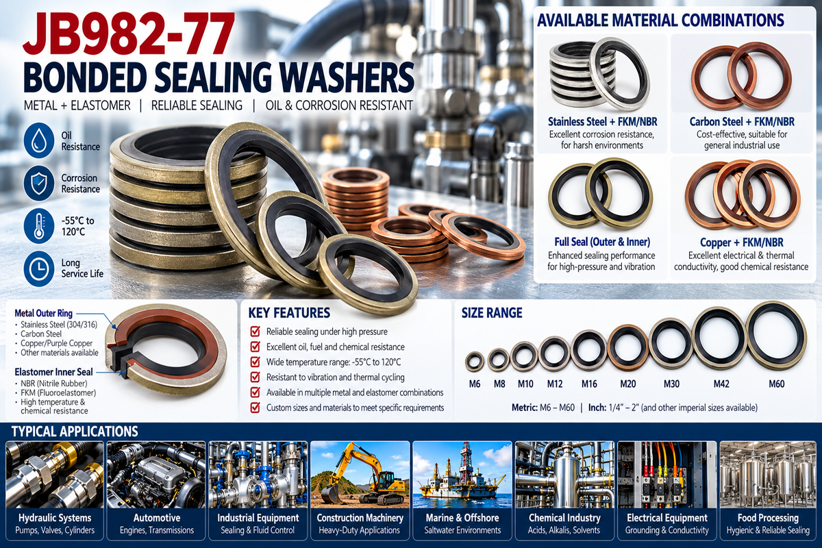
Special applications may use:
Stainless steel screws
Titanium screws
Custom machined fasteners
with elastomer sealing elements.
Material selection should consider:
Mechanical properties
Corrosion environment
Fluid
Galvanic interaction
Thread behavior
Galling
Installation
A corrosion-resistant screw does not automatically make the complete sealing system corrosion-resistant.
Corrosion-Resistant Fastener ≠ Corrosion-Resistant Assembly.
O-ring sealing can appear in many vehicle fluid and equipment systems.
Design considerations may include:
Temperature cycling
Oils
Coolants
Fuels
Vibration
Pressure cycling
Assembly automation
For EV applications, sealing may also be used around selected enclosure or fluid-management components.
But:
O-Ring Seal ≠ System IP Qualification.
A complete enclosure requires system-level validation.
Hydraulic and pneumatic applications require careful evaluation of:
Pressure
Pressure cycling
Clearance
Fluid
Temperature
Motion
Surface finish
Extrusion
Do not select the O-ring solely from nominal system pressure.
Pressure Rating ≠ Seal Design.
Pumps and valves can expose O-rings to combinations of:
Chemicals
Pressure
Temperature
Cycling
Motion
The fluid formulation can be especially important.
A material that performs well in one oil or chemical may not perform equally in another.
HVAC sealing applications can involve:
Refrigerants
Lubricants
Temperature cycling
Pressure
Outdoor exposure
Material compatibility should therefore be evaluated against the actual refrigerant/lubricant system rather than a generic statement such as "FKM is chemical resistant."
Commercial food-service equipment may expose seals to:
Water
Heat
Steam
Cleaning chemicals
Oils
Material selection may also require application-specific regulatory or customer requirements.
Do not assume that a polymer family alone establishes food-contact suitability.
Material Name ≠ Regulatory Approval.
Medical equipment can require demanding:
Cleanliness
Chemical compatibility
Material control
Documentation
But:
Silicone Material ≠ Medical Qualification.
If a medical application requires biocompatibility, sterilization compatibility or other regulated performance, those requirements must be specified and validated separately.
Procurement teams often compare replacement O-rings using:
Diameter
Cross-section
Color
Material family
Hardness
That may not establish functional equivalence.
A better comparison is:
Drawing + Revision + Dimensions + Compound + Hardness + Physical Properties + Fluid Compatibility + Temperature
+ Compression Set + Quality Grade + Surface Condition + Functional Testing + Documentation + Change Control
Therefore:
Same Size ≠ Same O-Ring Performance.
And:
Same Polymer Name ≠ Same Finished Performance.
When the O-ring is integrated with a fastener, qualification becomes more complex.
Compare both systems.
Drawing
Material
Thread
Head geometry
Mechanical properties
Surface treatment
Groove dimensions
Size
Compound
Hardness
Chemical compatibility
Temperature capability
Quality requirement
Installation torque
O-ring squeeze
Mating surface
Pressure
Leakage requirement
Functional testing
This is why:
Same Screw Dimensions ≠ Functional Equivalence.
For custom screws, plugs or machined components incorporating O-rings, procurement should ask:
Who controls the metal component drawing?
Who controls the O-ring specification?
How is groove geometry inspected?
How is elastomer material identified?
Is hardness specified?
Is the seal installed before shipment?
Is lubricant specified?
Is leak testing required?
What functional test applies?
How are material and process changes controlled?
Is traceability required?
This creates a more reliable sourcing process than purchasing the screw and seal independently without system ownership.
An O-ring may be inexpensive.
A sealing failure may not be.
Consider:
Total Installed Cost = Seal + Fastener + Assembly + Inspection + Leakage Test + Rework + Fluid Loss + Downtime + Field Service + Warranty Risk + Supply Risk
A low-cost seal that causes repeated leakage can become one of the most expensive components in the assembly.
Likewise, unnecessarily specifying an exotic elastomer can increase cost without improving performance.
The goal is not:
Most Expensive O-Ring
It is:
Correct Compound + Correct Geometry + Correct Installation + Validated Performance
Common causes include incorrect squeeze, material incompatibility, poor gland design, extrusion, installation damage, compression set, dynamic wear and contamination.
There is no single universal percentage. Required squeeze depends on seal type, cross-section, material, hardness, temperature,
pressure and whether the application is static or dynamic. Use the applicable design guidance and validate the application.
No. NBR is widely used with many petroleum-based oils, but compatibility depends on the actual compound, fluid formulation and temperature.
No. FKM and NBR have different chemical, temperature, mechanical and cost characteristics. The correct material depends on the application.
No. VMQ may provide useful temperature performance, but wear, tear strength, media compatibility and dynamic behavior must also be considered.
There is no universal pressure threshold. Extrusion risk depends on pressure, clearance, hardness, temperature, material and component deformation.
Not necessarily. Excessive torque may over-compress the seal, distort the assembly or damage the thread.
Not automatically. Higher hardness can improve extrusion resistance in some systems but may reduce conformability and affect low-pressure sealing and installation.
No. ISO dimensional or quality compliance does not replace application qualification.
Fluid absorption or chemical interaction may cause swelling. The exact compound, fluid, temperature and exposure time should be investigated.
Not automatically. Compound formulation, hardness, physical properties and quality can differ even when dimensions and polymer family are the same.
Provide the complete screw drawing, O-ring size, compound requirement, groove dimensions, mating component, fluid, temperature, pressure, installation torque and leakage requirement.
It may not be enough for a critical application. Exact compound requirements, fluid compatibility, temperature, quality requirements and customer specifications may also be needed.
Not for a critical sealing application. Compare compound, physical properties, compatibility, dimensions, quality requirements and functional performance.
JUXIN FASTENERS' relevant engineering strength is in fasteners and custom threaded components where sealing elements such as O-rings form part of the fastening assembly.
General loose O-ring supply should not be assumed unless specifically confirmed for the project.
Projects involving custom screws, threaded plugs, CNC machined components or drawing-based fasteners with O-ring sealing features are particularly relevant.
For accurate technical and commercial evaluation, provide:
2D drawing
3D model if available
Part number
Drawing revision
Application
Fastener type
Thread size
Thread pitch
Thread tolerance
Screw or plug material
Mechanical property requirement
Surface treatment
Head geometry
O-ring groove dimensions
O-ring nominal size
O-ring cross-section
Elastomer family
Compound specification if available
Hardness
Color if functionally required
Fluid or gas
Fluid concentration where relevant
Lubricant
Minimum operating temperature
Maximum continuous temperature
Peak temperature
Working pressure
Maximum pressure
Pressure spikes
Pressure direction
Static or dynamic seal
Motion type
Cycle rate where applicable
Extrusion clearance
Back-up ring requirement
Mating component material
Mating surface finish
Installation method
Installation torque
Leakage requirement
Pressure/leak test requirement
Cleanliness requirement
Regulatory or customer-specific requirements
Material documentation
Functional testing
PPAP or customer-specific documentation where applicable
Annual volume
Existing approved sample for second-source development where available
For a failed sealing assembly, also provide:
Photos of the failed O-ring
Failure location
Service time
Operating history
Fluid exposure
Temperature history
Pressure history
Existing groove dimensions
Existing material specification
These details allow the investigation to focus on the actual failure mechanism rather than simply replacing the seal.
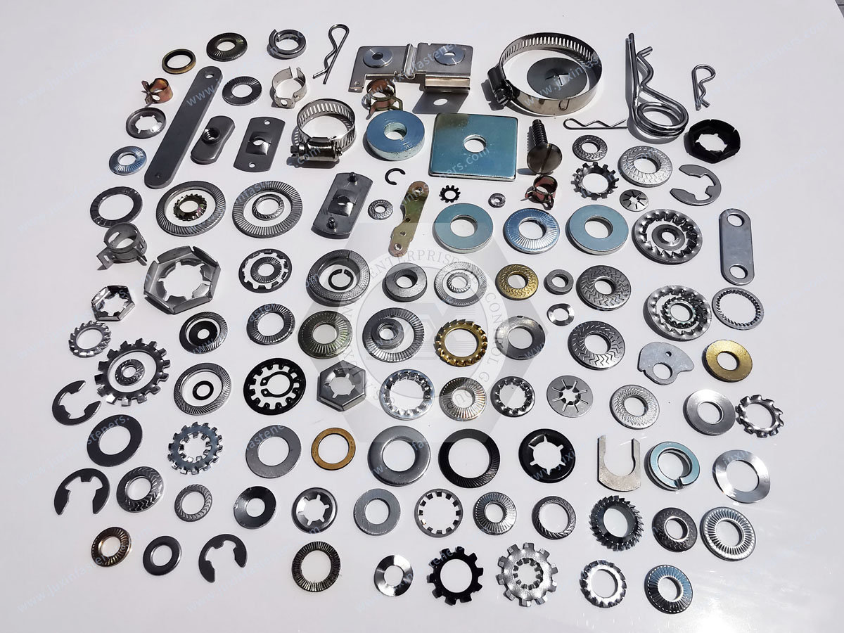
This page should connect internally with existing JUXIN FASTENERS resources covering:
Custom sealing screws and threaded fasteners
CNC machined threaded components
ISO metric thread tolerances and 6H/6g thread fit
BSP vs. NPT pipe threads
PTFE material and coated fastener applications
Stainless steel fasteners
Titanium fasteners
Fastener surface finish selection
Bolt tightening and over-torque
Torque, friction and preload
Threaded inserts for plastics
Automotive fastening solutions
HVAC fastening solutions
Medical equipment fasteners
Second-source fastener qualification
Use the existing indexed JUXIN FASTENERS URL when implementing each internal link.
The intended content path is:
Leakage Problem → Failure Morphology → O-Ring Material → Groove Geometry → Pressure & Temperature
→ Installation → Fastener/Seal Integration → Validation → Supplier Qualification → RFQ
When an O-ring fails, replacing it with:
A harder O-ring
A more expensive elastomer
A larger cross-section
A different supplier
may solve nothing if the actual problem is:
Incorrect groove depth
Excessive clearance
Installation damage
Pressure spikes
Wrong fluid compatibility
Poor surface condition
The correct engineering chain is:
Application → Fluid → Temperature → Pressure → Motion → Elastomer → O-Ring Size → Groove → Squeeze → Clearance → Surface → Installation → Validation
Remember:
O-Ring Failure ≠ O-Ring Defect.
Same Size ≠ Same O-Ring Performance.
Same Polymer Name ≠ Same Finished Performance.
More Compression ≠ Better Sealing.
Higher Hardness ≠ Better Seal.
Higher Installation Torque ≠ Better Seal.
Back-Up Ring ≠ Automatic High-Pressure Qualification.
Standard Compliance ≠ Application Qualification.
For design engineers, this framework helps identify the real cause of leakage before redesigning the component.
For quality teams, it turns failed seals into useful diagnostic evidence.
For procurement and supplier-development teams, it prevents replacement parts from being approved on size, color and generic material name alone.
JUXIN FASTENERS supports OEM, Tier-1, Tier-2 and industrial manufacturers with drawing-based screws, bolts, threaded plugs,
stainless and titanium fasteners, CNC machined threaded components and custom fastening parts incorporating application-specific sealing features.
For an O-ring sealing screw, custom threaded plug, machined sealing component, leakage problem or second-source qualification project,
send your drawing, revision, fastener material, O-ring requirement, groove geometry, fluid, temperature, pressure, installation conditions and annual volume for technical review.
JUXIN FASTENERS
Email: info@juxinfasteners.com
Website: www.juxinfasteners.com
Contact Us
Tel.:
+86 020 8621 0320
+86 020 3121 6067
E-mail:
Technical Support:
Navigation
SEND INQUIREY



