
Call Us
+86 136 6007 9809
Call Us
+86 136 6007 9809

Sep. 21, 2026
Industrial robots, automated production machinery, automated guided vehicles, autonomous mobile robots,
machine-vision systems and compact automation equipment increasingly package more electronics, sensors, drives, communication hardware and mechanical components into restricted physical envelopes.
As equipment becomes smaller and more integrated, the fastener itself becomes part of the packaging problem.
A screw joint that appears insignificant on a conventional industrial cabinet can create a serious interference problem inside a compact robot controller, sensor enclosure or mobile automation platform.
Where a removable threaded attachment point is required near an accessible sheet-metal edge, low-profile clip-on nuts for robotics can provide a compact fastening architecture.
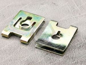
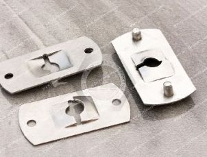
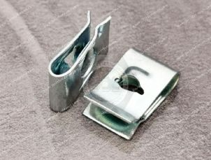
Low-profile U-nuts, J-nuts, strong-grip clip-on nuts and enclosed-thread spring fasteners can create captive threaded positions without requiring a conventional loose nut behind the panel.
However, the correct engineering question is not simply:
“How thin is the clip nut?”
It is:
“What total three-dimensional fastening envelope does the assembled joint require?”
The complete package should be evaluated as:
Clip Nut + Panel + Screw + Screw Head + Screw Intrusion + Tool Access + Adjacent Components + Required Assembly Movement
This 3D-envelope approach is one of the most important considerations when specifying compact fasteners for robotics and industrial automation.
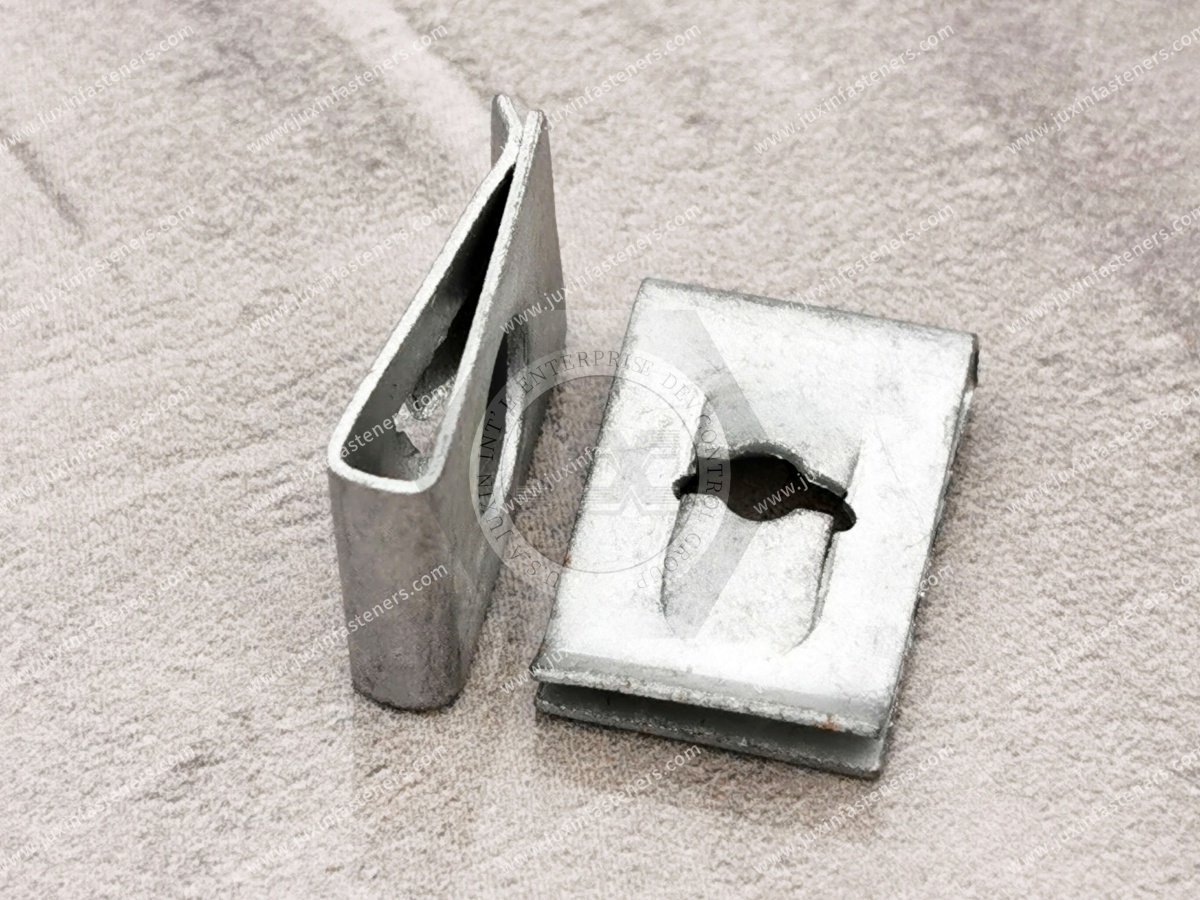
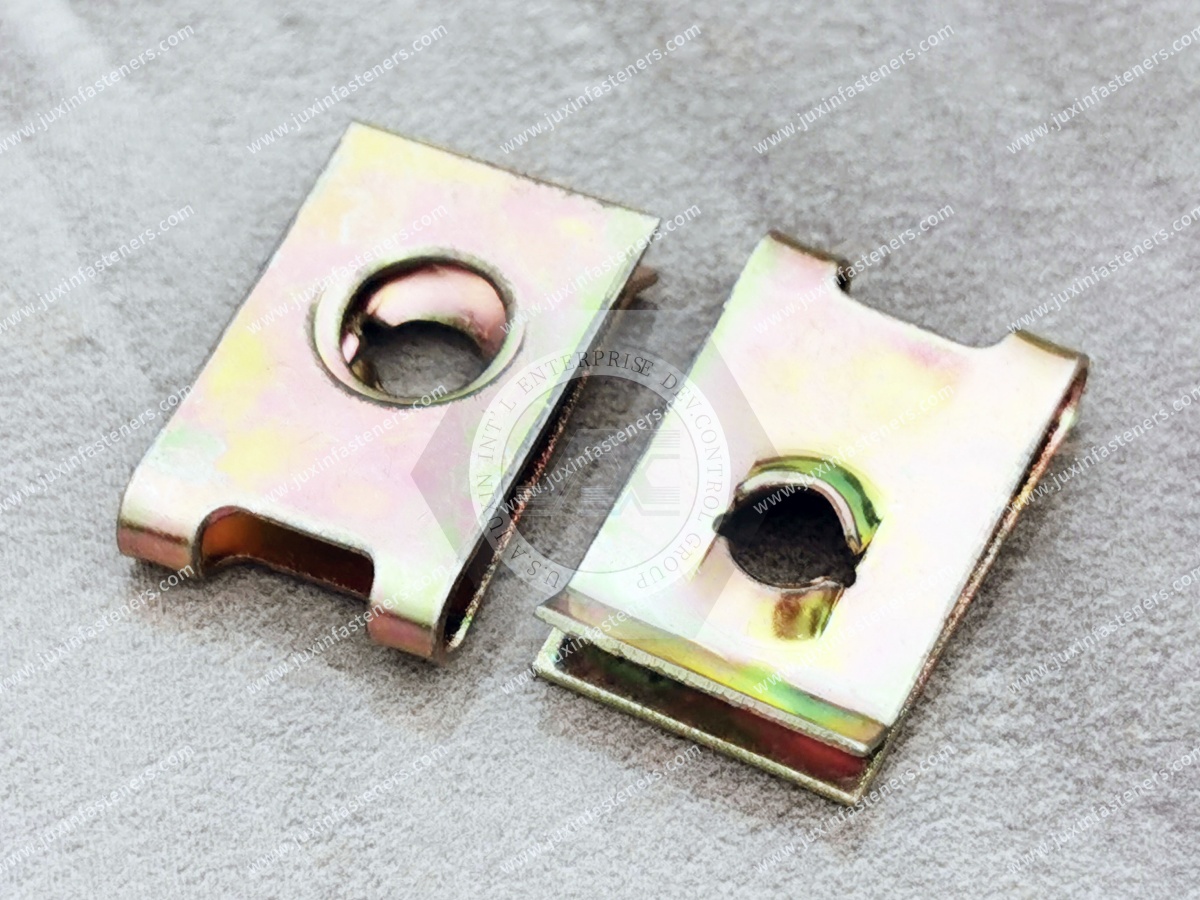
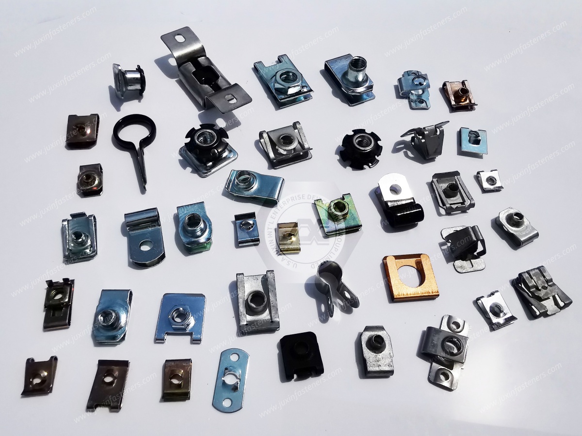
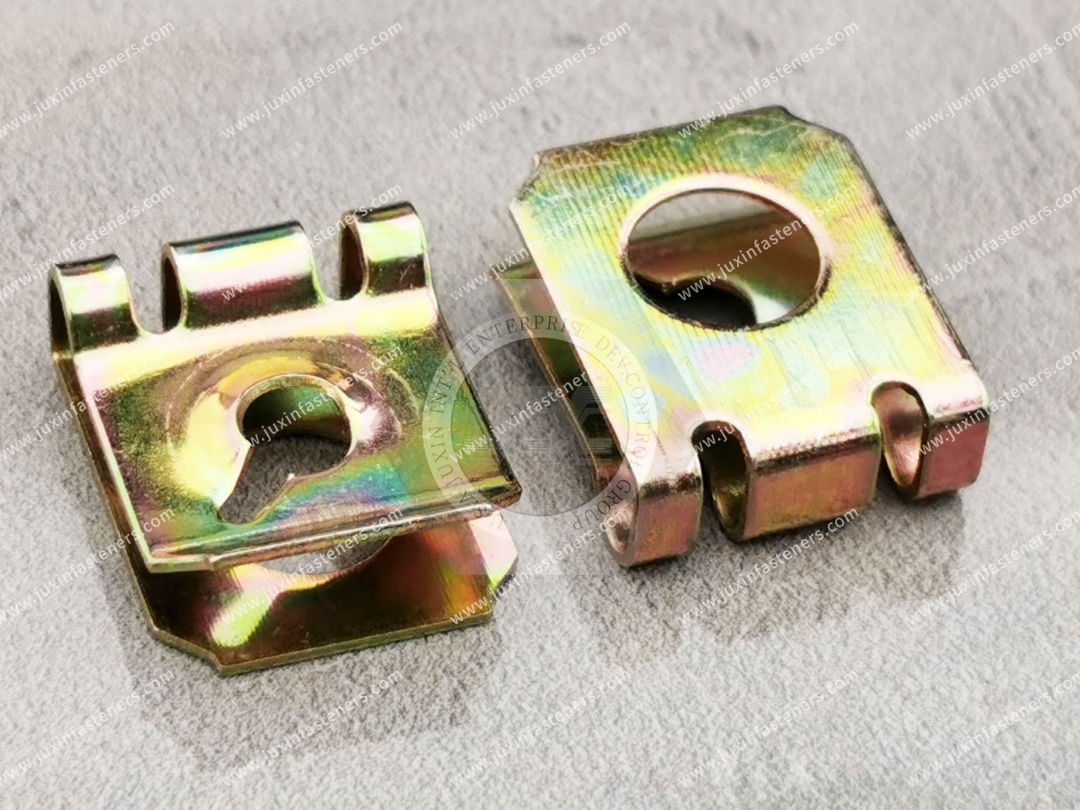
A low-profile clip-on nut is an edge-mounted spring fastener designed to provide a captive threaded or screw-engagement point while controlling protrusion within a restricted assembly envelope.
Possible configurations include:
low-profile U-nuts;
low-profile J-nuts;
strong-grip low-profile clip-on nuts;
enclosed-thread clip nuts;
compact machine-screw spring nuts;
tapping-screw spring clips;
drawing-specific spring fasteners.
The term low-profile should describe an actual geometric requirement rather than a generic marketing claim.
A low-profile fastener is not automatically:
stronger;
weaker;
more vibration resistant;
more fatigue resistant;
more suitable for robotics.
Its primary advantage is geometric.
Mechanical performance must be evaluated separately.
Therefore:
Low Profile ≠ High Strength
and:
Low Profile ≠ Vibration Qualification
Potential applications include appropriate:
robot controller cabinets;
compact electronics housings;
sensor enclosures;
machine-vision housings;
auxiliary control boxes;
AGV body covers;
AMR service covers;
battery-compartment access panels;
communication-module covers;
non-structural protective panels;
service-access covers;
auxiliary brackets.
The suitability of the fastener depends on the actual load path and operating environment.
Robotic equipment contains very different mechanical zones.
A useful engineering approach is to classify the fastening location before selecting a clip.
These can include major:
arm structures;
axis structures;
load-bearing joints;
base attachments.
Generic clip-on nuts should not automatically be selected for these locations.
These may include attachments associated with:
actuators;
gearboxes;
servo systems;
major sensors;
functional motion components.
These locations require dedicated mechanical evaluation.
Examples can include appropriate:
protective covers;
electronics covers;
cable-access panels;
auxiliary sensor housings.
Clip-on nuts may be candidates where the load, geometry and dynamic environment permit.
These can include:
controller covers;
service panels;
communication equipment covers;
secondary internal brackets.
This is often a natural application zone for edge-mounted clip-on nuts.
The key principle is:
Robotics Application ≠ Robot-Arm Structural Application
Traditional fastener selection often concentrates on:
thread diameter;
panel thickness.
Compact automation requires more.
Engineers may also need to control:
clip height above panel;
clip depth behind panel;
throat depth;
screw-head height;
screw-tip intrusion;
installation tool clearance;
driver approach angle;
neighboring cable clearance;
PCB clearance;
connector clearance;
moving-part sweep envelope.
This creates a true three-dimensional fastening problem.
The clip may project above or below the sheet-metal surface.
This can interfere with:
adjacent panels;
housings;
cable routing;
moving components.
The permissible protrusion should therefore be defined on the assembly drawing.
Throat depth controls how far the clip reaches from the panel edge to the threaded position.
Reducing external profile does not automatically reduce throat depth.
Therefore:
Low Height ≠ Short Throat Depth
These dimensions should be controlled independently.
A low-profile clip can still create an interference problem if the screw is too long.
The screw tip may interfere with:
PCB assemblies;
cable harnesses;
batteries;
sensors;
connectors;
moving components.
Therefore the complete installed screw length matters.
A compact clip does not solve an external clearance problem if the screw head is too tall.
The complete assembly should therefore consider:
Clip Profile + Screw Head Profile
The fastener may physically fit while the assembly tool cannot reach it.
Engineers should consider:
screwdriver diameter;
bit length;
driver-body clearance;
approach angle;
nearby components;
automated screwdriving equipment.
This is especially important in densely packaged robotic controllers.
This is a common prototype-to-production failure.
CAD review may confirm that the fastener fits within the enclosure.
During production, however, the screwdriver or automated driver collides with:
cabinet walls;
electronics;
cable ducts;
brackets.
Therefore:
Fastener Clearance ≠ Assembly Clearance
Compact sheet-metal housings often use narrow flanges to maximize internal volume.
This creates competing requirements:
minimize flange width;
maintain sufficient edge material;
provide correct hole position;
accommodate the clip throat;
maintain assembly clearance.
Low-profile clip selection must therefore consider more than overall height.
Hole setback is the distance between the panel edge and the screw-hole center.
It must match the clip geometry.
Incorrect setback can create:
thread misalignment;
cross-threading;
clip migration;
difficult screw starting;
panel-edge deformation.
Terms such as:
narrow pitch;
compact edge distance;
slim flange
are not sufficiently precise for production sourcing.
The drawing should specify the actual:
edge-to-hole distance;
tolerance;
hole diameter;
flange geometry.
There is no single universal minimum edge distance for all low-profile clip-on nuts.
The required geometry depends on:
clip architecture;
panel material;
panel thickness;
hole diameter;
load;
flange stiffness.
Therefore:
One Edge-Distance Rule ≠ Every Robotics Clip Nut
Clip grip should match the actual panel thickness range.
If the panel is too thin relative to the clip geometry, retention may be insufficient.
If it is too thick, installation can create excessive spring deflection.
For detailed guidance, see Panel Thickness Selection Guide.
Robotic and automation enclosures can include:
paint;
powder coating;
plating;
other surface finishes.
The clip interacts with the finished panel.
Therefore:
Nominal Sheet Thickness ≠ Automatically Finished Grip Thickness
This distinction remains fundamental.
Describes how securely the clip remains on the panel before and during screw installation.
Depends on the complete:
Clip Thread + Screw + Panel + Attached Component
system.
Therefore:
High Clip Retention ≠ Automatically High Joint Strength
Gemini's statement that spring steel clip force prevents screw back-out is too broad.
The spring arms primarily retain the clip on the panel.
Screw-joint stability can depend on:
initial clamp;
friction;
joint stiffness;
transverse movement;
dynamic loading;
locking feature where required.
Therefore:
Panel Grip Force ≠ Screw-Locking Torque
Robotic systems can create dynamic inputs through:
acceleration;
deceleration;
direction reversal;
servo motion;
vibration;
external machine excitation;
mobile-platform travel.
These should not be treated as one generic “robot vibration” condition.
An articulated robot can experience repeated acceleration and deceleration.
A controller cabinet near industrial machinery may experience continuous vibration.
An AGV may experience floor-induced shocks.
These produce different load histories.
Therefore:
Robot Motion ≠ One Universal Vibration Profile
For a component mounted on a moving subsystem, inertial load depends on the accelerated mass.
A simple engineering relationship is:
Force = Mass × Acceleration
This means a small lightweight cover and a heavy control module can create very different fastener demands even when mounted on the same robot.
Repeated reversal can change the direction of load acting on:
panel;
bracket;
fastener.
This can create cyclic interface movement that does not occur in a stationary cabinet.
Moving-subsystem fastening should therefore be evaluated differently from stationary-controller fastening.
A robotic cover, sensor bracket or electronics housing can have its own:
mass;
stiffness;
natural frequencies.
Local motion at the fastener can therefore differ from the nominal machine input.
Thus:
Machine Motion Input ≠ Automatically Local Fastener Load
A strong-grip clip may provide high panel retention.
That does not establish resistance to screw loosening or fatigue in every robotic application.
The complete joint should be validated where dynamic performance matters.
Rattle can depend on:
clamp;
clearance;
panel stiffness;
vibration;
resonance;
fastener spacing.
Increasing clip grip alone may not solve it.
Vibration creates repeated loading.
Fatigue is progressive material damage caused by cyclic stress.
Whether a spring clip experiences fatigue depends on:
stress amplitude;
clip geometry;
material condition;
surface condition;
number of cycles.
Therefore:
Vibration Exposure ≠ Defined Fatigue Life
ISO 10218-1 addresses safety requirements for industrial robots within its scope.
ISO 10218-2 addresses industrial robot applications and robot cells, including integration and lifecycle considerations within its scope.
These standards provide important system-level safety context for robotics engineering.
However, they are not dimensional or mechanical product standards for clip-on nuts.
Therefore:
Robot System Designed to ISO 10218 Requirements ≠ Clip-On Nut “ISO 10218 Certified”
Fastener suitability remains an application-specific engineering decision.
AGVs and AMRs can create fastening applications similar to robotic equipment, but mobile-platform requirements should not automatically be inferred from industrial robot standards.
The applicable requirements depend on the specific:
vehicle;
platform;
operating environment;
safety architecture;
application.
Potential clip-on nut applications can include appropriate:
body covers;
service panels;
electronics covers;
sensor-access covers;
battery-compartment service panels;
communication-module housings.
The fastener should be evaluated against:
vibration;
floor shock;
service access;
panel geometry;
environmental exposure.
AGVs and mobile robots can use removable battery access covers.
Clip-on nuts may be useful where:
edge access is available;
the attachment is mechanically appropriate;
serviceability is required.
However, a generic clip-on nut should not automatically be treated as:
battery structural hardware;
electrical isolation hardware;
sealing hardware;
high-voltage hardware.
Robot controllers can contain:
drives;
power supplies;
communication modules;
safety electronics;
cooling equipment;
cable routing.
Space around covers and internal brackets can be limited.
Low-profile clip-on nuts can help control the fastening envelope where the joint architecture permits edge-mounted fastening.
A fastener near electronic hardware should be evaluated for:
screw-tip intrusion;
conductive clearances;
cable contact;
PCB interference;
connector interference.
Mechanical fit alone is not enough.
A compact metal fastener should not automatically be assumed safe merely because it physically fits near electronics.
Electrical equipment design may require specific:
clearance;
creepage;
insulation;
grounding;
bonding
considerations.
These are system-level electrical requirements.
Metal-to-metal contact does not automatically establish a controlled grounding or bonding path.
Surface finishes and coatings can influence electrical contact.
If electrical bonding is required, it should be engineered and validated separately.

Sensors used in automation can require compact protective housings.
Potential clip-on nut applications include suitable:
access covers;
secondary brackets;
protective panels.
The fastener should not interfere with:
connectors;
cable glands;
sensor field of view;
moving equipment.
Machine-vision systems can contain:
cameras;
lenses;
lighting;
electronics.
Low-profile fasteners can be useful where the enclosure is tightly packaged.
However, fastener placement should not create interference with optical components or adjustment mechanisms.
Some actuator and motion-control equipment includes removable covers.
Clip-on nuts can be considered for appropriate auxiliary enclosure attachments.
They should not automatically be specified for primary actuator load paths.
Stationary control panels are often less dynamically demanding than moving robot-arm assemblies.
Potential applications include:
service covers;
secondary internal brackets;
cable-management covers;
electronics panels.
This creates an important sourcing distinction:
Stationary Automation Cabinet ≠ Moving Robot Subassembly
Automated production systems are often designed around high equipment availability.
Maintenance technicians may require rapid access to:
sensors;
control electronics;
communication modules;
wiring;
cooling fans.
Replaceable clip-on nuts can support serviceability where the enclosure design permits them.
Repeated access can affect:
clip threads;
screw threads;
panel edge;
coating;
spring geometry.
If a panel will be opened repeatedly, the expected service-cycle requirement should be defined.
For frequently serviced automation equipment, validation can evaluate:
screw-start consistency;
installation torque;
thread condition;
clip retention;
panel-edge condition
after repeated removal and reinstallation.
Industrial automation manufacturers may themselves use automated assembly.
A clip-on nut that works during manual prototype assembly may behave differently on a production line.
Potential issues include:
clip position variation;
screw alignment;
driver access;
part feeding;
orientation.
Not every clip-on nut geometry is automatically suitable for:
bowl feeding;
robotic placement;
automated insertion.
If automated feeding is required, this should be stated in the RFQ.
Automated screwdriving generally benefits from consistent:
hole location;
clip position;
thread alignment;
driver approach.
Small alignment errors can create:
cross-threading;
abnormal rundown torque;
assembly stoppages.
Reducing fastener dimensions can create tradeoffs.
A very compact design may have:
reduced lead-in;
tighter alignment tolerance;
less installation clearance.
Therefore:
Smallest Fastener ≠ Automatically Best Production Fastener
The optimum fastener balances:
packaging;
mechanical performance;
assembly access;
serviceability;
manufacturing robustness.
This is more useful than minimizing fastener size alone.
Specification-controlled carbon spring steel can provide the elastic behavior required for many low-profile clip designs.
Final performance depends on:
material condition;
thickness;
forming;
heat treatment;
geometry.
Material name alone does not establish robotics performance.
Electroplated carbon spring-steel clips can provide corrosion protection for appropriate automation environments.
Where applicable, ISO 4042 provides requirements for electroplated coating systems on fasteners, including clips.
The required coating system should still be defined by the application or customer specification.
For susceptible hardened or high-strength spring-steel clips, manufacturing and electroplating can require hydrogen-embrittlement risk controls.
Risk depends on factors including:
material;
hardness/strength;
processing;
coating route;
applied stress.
No universal baking recipe should be assigned to every robotics clip-on nut.
Stainless spring materials may be considered for environments involving:
humidity;
selected chemicals;
outdoor mobile equipment;
corrosion exposure.
However:
Stainless ≠ Corrosion-Proof
and:
Stainless ≠ Automatically Better for Every Robotic Application
Material substitution can also change spring behavior and should be validated.
Automation equipment can operate in very different environments.
Examples include:
clean indoor manufacturing;
humid industrial plants;
warehouses;
outdoor logistics;
food or chemical processing environments with additional requirements.
The actual environment should determine the material and finish specification.
Where salt-spray testing is specified, ISO 9227 provides recognized laboratory test methods.
The required:
method;
duration;
acceptance criteria
should come from the applicable customer or product specification.
Laboratory salt-spray exposure should not be directly converted into:
years of AGV operation;
robot controller service life;
outdoor automation lifetime.
Field corrosion depends on the actual environment.
Industrial robotics commonly uses metric hardware.
RFQs should explicitly specify:
nominal diameter;
pitch;
mating screw;
screw material and finish where relevant.
For further guidance, see Metric Clip-On Nuts Selection Guide.
Two M5 clip-on nuts can differ in:
total profile height;
throat depth;
grip range;
hole setback;
spring geometry;
thread construction;
material;
finish.
Therefore:
Thread Size ≠ Complete Fastener Specification
Low-profile designs are particularly useful where packaging is constrained.
Conventional clip-on nuts may be preferable where:
more space is available;
geometry provides better assembly access;
a different grip range is required.
The smallest profile should not automatically be selected.
Weld nuts can create permanently located threaded points but require an appropriate welding process and compatible panel architecture.
Clip-on nuts can provide:
no welding at the installation location;
replaceability;
post-finish installation potential.
The correct choice depends on the equipment architecture.
Self-clinching fasteners can provide installed threaded points in compatible sheet materials and geometries.
Clip-on nuts differ because they mount from a panel edge and can be replaceable.
Neither architecture is universally superior.
Blind rivet nuts can establish threaded attachment away from a panel edge where one-side installation is required.
Clip-on nuts require a suitable accessible edge but can avoid a permanent deformation installation process.
Therefore:
Edge Access → Clip-On Architecture Candidate
Mid-Panel Blind Thread → Rivet-Nut Architecture Candidate
For broader comparison, see Sheet-Metal Fastener Selection Guide.
Potential issues include:
clip migration;
cross-threading;
thread stripping;
screw loosening;
panel-edge deformation;
clip fatigue;
coating damage;
component interference;
tool-access failure.
For detailed troubleshooting, see Clip-On Nut Failure Analysis.
Possible causes include:
excessive clip height;
excessive screw length;
incorrect throat depth;
insufficient CAD envelope review.
This is particularly important near PCBs, connectors and cable harnesses.
The fastener itself may fit, but the driver may collide with adjacent equipment.
The corrective action may require changing:
fastener location;
screw-head style;
driver access;
enclosure geometry.
Potential causes include:
wrong grip range;
panel-thickness variation;
insufficient retention;
dynamic panel movement.
Investigate:
joint clamp;
friction;
transverse movement;
dynamic loading;
locking strategy.
Do not automatically increase clip spring force.
Investigate:
spring deflection;
dynamic panel movement;
geometry;
material condition;
cyclic stress.
Possible contributors include:
incorrect hole setback;
clip misalignment;
driver misalignment;
screw mismatch.
| Engineering Requirement | Selection Consideration |
|---|---|
| Restricted vertical clearance | Low-profile clip may be suitable |
| Restricted backside clearance | Control clip depth and screw intrusion |
| Narrow flange | Validate setback, edge distance and throat depth |
| Accessible panel edge | Clip-on architecture may be suitable |
| Mid-panel blind thread | Consider another fastener architecture |
| Moving enclosure | Evaluate acceleration and cyclic loading |
| Stationary controller cabinet | Clip-on nut may offer efficient serviceability |
| Robot structural joint | Dedicated structural fastening required |
| AGV body/service cover | Evaluate shock, vibration and environment |
| PCB close behind panel | Control screw-tip intrusion |
| Automated screwdriving | Validate alignment and tool access |
| Automated clip feeding | Verify fastener feedability separately |
| Repeated maintenance | Define service-cycle requirement |
Is the fastener used in:
industrial robot;
controller cabinet;
automated machine;
AGV;
AMR;
machine-vision system;
sensor enclosure;
another automation system?
Classify the location as:
stationary;
moving auxiliary assembly;
motion-critical assembly;
primary structural assembly.
Is it retaining:
cover;
service panel;
electronics enclosure;
sensor housing;
auxiliary bracket?
Specify:
maximum clip height;
maximum backside projection;
throat depth;
screw-head clearance;
screw-tip clearance;
tool-access envelope.
Specify:
material;
thickness;
tolerance;
finish;
flange width;
hole diameter;
hole setback.
Specify:
thread diameter;
pitch;
screw material;
screw finish;
screw length;
head style.
Include where applicable:
acceleration;
deceleration;
vibration;
shock;
direction reversal;
mounted mass.
Specify:
temperature;
humidity;
indoor/outdoor;
contamination;
corrosion requirement.
Specify:
expected access frequency;
removal/reinstallation cycles;
replacement strategy.
Specify whether installation is:
manual;
semi-automated;
fully automated.
Evaluate:
Production Clip + Production Panel + Production Screw + Adjacent Components + Production Driver + Dynamic Environment
Robotics engineering teams can reduce iteration by defining a fastener keep-out zone in CAD.
The keep-out volume can include:
clip envelope;
screw envelope;
driver envelope;
installation movement.
This provides a more realistic packaging check than reviewing the fastener body alone.
A low-profile clip fitting one prototype does not establish production suitability.
Production introduces:
panel tolerance;
bend tolerance;
hole-position tolerance;
coating variation;
fastener variation;
screw variation;
assembly-tool variation.
Dynamic service adds another layer.
Two suppliers may both describe a component as:
M5 Low-Profile Robotics U-Nut
while their parts differ in:
height;
throat depth;
grip range;
hole setback;
spring geometry;
thread geometry;
material condition;
coating.
Therefore:
Same Catalogue Description ≠ Same Packaging or Assembly Behavior
Purchasing teams should consider more than unit price.
A useful model is:
Fastener Cost + Installation Cost + Packaging Impact + Assembly Downtime Risk + Rework Cost + Service Cost
A low-cost fastener that creates driver interference or automated assembly stoppages can create a much higher installed cost.
Robotics and automation engineers may search:
low-profile clip-on nuts for robotics;
robot enclosure fasteners;
industrial automation clip nuts;
compact U-nuts;
low-profile spring nuts;
AGV panel fasteners;
robot controller cabinet fasteners;
compact sensor housing fasteners.
These searches indicate engineering-selection intent.
Sourcing teams may search:
robotics clip nut supplier;
low-profile U-nut manufacturer;
automation fastener supplier;
robot enclosure fastener manufacturer;
AGV clip nut supplier;
custom low-profile spring fasteners.
These searches indicate commercial supplier-selection intent.
When requesting engineering and commercial evaluation from JUXIN FASTENERS, provide where applicable:
equipment type;
robotic/automation subsystem;
moving or stationary location;
fastener function;
2D drawing;
3D model where available;
assembly drawing;
current fastener sample;
current supplier part number;
maximum fastener profile;
maximum backside projection;
throat-depth requirement;
screw-head clearance;
screw-tip clearance;
driver-access envelope;
adjacent component clearance;
PCB clearance where relevant;
cable clearance where relevant;
panel material;
panel thickness;
thickness tolerance;
panel finish;
flange width;
bend geometry;
hole diameter;
hole setback;
thread size;
thread pitch;
mating screw specification;
screw material;
screw finish;
screw length;
screw-head style;
clip-retention requirement where defined;
joint mechanical requirement;
mounted component mass where relevant;
acceleration/deceleration requirement;
vibration requirement;
shock requirement;
operating temperature;
humidity;
corrosion requirement;
coating specification;
corrosion-test requirement where applicable;
maintenance-access requirement;
expected service cycles;
installation method;
screwdriving method;
automated-feeding requirement;
automated-insertion requirement;
packaging requirement;
inspection requirement;
documentation requirement;
sample quantity;
prototype quantity;
production quantity;
estimated annual demand;
program timing;
customer-specific requirements.
They can provide captive threaded attachment while reducing fastener protrusion in compact sheet-metal enclosures.
Not automatically. Low profile primarily describes packaging geometry rather than strength.
Not automatically. Clip retention and screw-joint stability are separate functions.
They may be suitable for certain auxiliary covers or enclosures after application-specific validation, but generic clip-on nuts should not automatically be used for primary structural or motion-critical robot joints.
They can be considered for appropriate body covers, service panels and auxiliary enclosures where the geometry, dynamic loading and environment permit.
No. ISO 10218 addresses industrial robot and robot-application safety within its scope. It is not a clip-on nut product specification.
No. The applicable standards and requirements depend on the mobile platform and application.
There is no single dimension. Engineers should consider the complete 3D envelope including clip height, backside projection, throat depth, screw head, screw-tip intrusion and tool access.
No. A smaller fastener can create tighter alignment and assembly constraints. The best solution balances packaging and production robustness.
The installed screw-tip envelope should be controlled, along with electrical and mechanical clearance requirements.
Some designs may be suitable, but automated feeding, orientation, placement and screwdriving should be validated for the selected fastener.
JUXIN FASTENERS can review available 2D drawings, 3D models, fastener envelope requirements, panel geometry, screw requirements,
dynamic conditions, service requirements and production demand to identify candidate clip-on nut configurations for evaluation.
A sourcing request may begin:
“Need M5 low-profile clip nut for robot controller.”
That is not enough to define the application.
Engineering should determine:
Is the Fastener on a Moving or Stationary Assembly?
What Does It Retain?
What Is the Maximum Clip Height?
How Much Backside Clearance Is Available?
How Long Can the Screw Project Beyond the Thread?
Is a PCB, Cable or Connector Nearby?
Can the Driver Reach the Screw?
What Is the Panel Thickness?
What Is the Flange Width?
What Is the Hole Setback?
What Screw Is Used?
What Dynamic Loads Apply?
How Often Will the Cover Be Removed?
The sourcing path becomes:
Automation System → Moving / Stationary Zone → Fastener Function → 3D Envelope → Panel Geometry
→ Thread / Screw → Dynamic Environment → Material / Finish → Service Requirement → Production Assembly → Samples → Assembly Validation → Controlled Specification → Production RFQ
This converts a generic compact-fastener inquiry into an engineering-controlled sourcing process.
JUXIN FASTENERS supports OEM and industrial sourcing for appropriate robotics and automation fastening applications, including:
low-profile clip-on nuts;
low-profile U-nuts;
low-profile J-nuts;
strong-grip clip-on nuts;
enclosed-thread clip nuts;
metric spring nuts;
carbon spring-steel clips;
stainless spring clips where appropriate;
drawing-based spring fasteners.
Potential applications include appropriate:
robot controller cabinets;
automation control equipment;
AGV and AMR body covers;
sensor housings;
machine-vision enclosures;
electronics service panels;
communication-module covers;
battery service panels;
auxiliary brackets;
compact machinery enclosures.
For related engineering guidance, see:
Low-Profile Strong-Grip Clip-On Nuts
Low-Profile Strong-Grip Clip-On Nuts for Flush-Mount Assemblies
Strong-Grip Clip-On Enclosed Hex Nuts
Clip-On Nuts for Flanged Edges
Panel Thickness Selection Guide
Sheet-Metal Fastener Selection Guide
Metric Clip-On Nuts Selection Guide
Carbon Steel Clip-On Nuts: Material & Coating Guide
For a robotics or industrial automation clip-on nut RFQ, send your drawing or 3D model, moving/stationary application,
available fastener envelope, panel material and thickness, flange geometry, hole setback, mating screw specification,
dynamic requirements, service-cycle requirements, sample quantity and estimated annual demand to:
For robotics and automation fastening, the correct sourcing question is not simply:
“What is the smallest clip nut available?”
It is:
“Which clip geometry provides the required threaded attachment while fitting the complete 3D envelope,
maintaining assembly-tool access and supporting the actual mechanical and service requirements of the automation system?”
 MORE NEWS
Contact Us
Tel.:
+86 020 8621 0320
+86 020 3121 6067
E-mail:
Technical Support:
Navigation
SEND INQUIREY