
Call Us
+86 136 6007 9809
Call Us
+86 136 6007 9809

Aug. 24, 2026
Stainless Steel CNC Machining for Robotics and Custom OEM Precision Components
Robotics manufacturers require precision mechanical components that support accurate positioning, reliable motion, secure assembly, and repeatable operation.
Industrial robots, collaborative robots, robotic grippers, automated handling systems,
and end-of-arm tooling incorporate numerous mechanical interfaces that must meet application-specific dimensional and functional requirements.
For selected applications, stainless steel CNC machining provides a flexible manufacturing solution for custom robotic components requiring accurate geometry,
corrosion resistance, controlled surface condition, and consistent dimensional quality.
Typical components include precision shafts, locating pins, bushings, sleeves, threaded adapters, mounting blocks, gripper components, tooling interfaces, and custom fastening hardware.
However, the correct material and manufacturing process depend on the component's function within the robotic system.
A static stainless steel mounting spacer has different engineering requirements from a high-speed rotating shaft, heavily loaded joint component, or lightweight robotic end-effector.
Material selection should therefore consider strength, stiffness, weight, inertia, fatigue, wear, corrosion resistance, and manufacturing cost.
JUXIN FASTENERS supports drawing-based inquiries for custom stainless steel CNC machined parts and precision fastening hardware used in robotics and automation equipment.
Depending on component geometry and production requirements, suitable processes may include CNC turning, Swiss-type machining, CNC milling, drilling, tapping, threading, grooving, and combined turning-milling operations.
Manufacturing feasibility, material specifications, achievable tolerances, inspection requirements, production quantities, and commercial terms should be confirmed for each project.
Robotics Applications for Custom CNC Machined Components
Robotic systems contain mechanical assemblies that require accurate mounting, positioning, spacing, and connection.
The appropriate component design depends on the robot architecture, payload, motion profile, operating environment, and maintenance requirements.
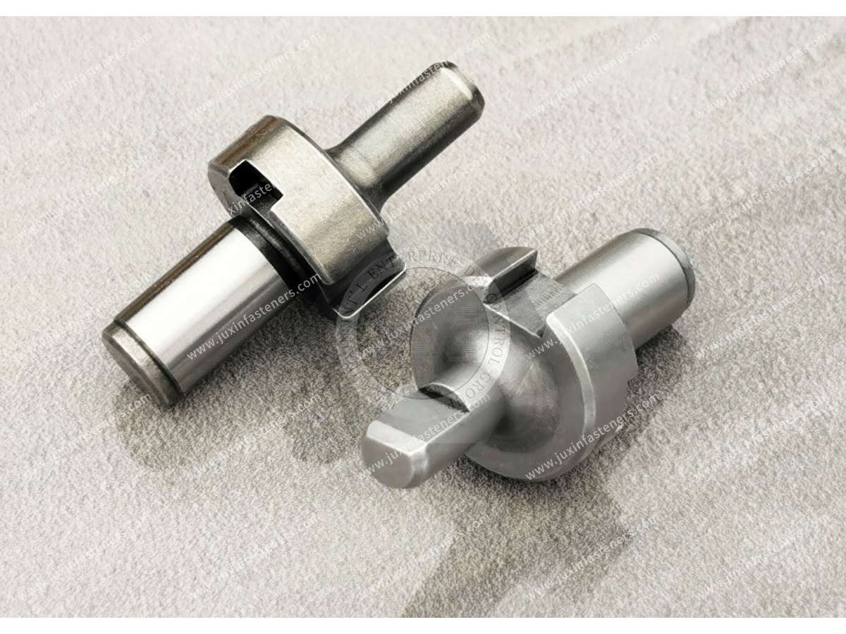
Industrial Robot Mechanical Interfaces
Industrial robotic systems may incorporate precision shafts, locating pins, threaded adapters, mounting blocks, and custom mechanical interfaces.
CNC machining can support components requiring controlled diameters, shoulders, threads, grooves, and accurately positioned mounting features.
However, critical robot joint and drive components may require specialized engineering analysis, material specifications, heat treatment, and validation.
General CNC machining capability does not establish suitability for safety-critical or high-load robot joints.
Collaborative Robot Tooling and Mounting Hardware
Collaborative robots may use custom mounting plates, spacers, threaded adapters, locating components, and tooling interfaces.
CNC machining can provide accurate geometry where standard hardware does not meet the required mounting arrangement.
However, collaborative robot applications must consider the complete system's payload, mass distribution, safety requirements, and operating conditions.
A machined component does not independently establish compliance with collaborative robot safety requirements.
Robotic End-Effectors and Grippers
Robotic end-effectors may incorporate precision mounting blocks, adapter components, gripper fingers, locating pins, and threaded fastening hardware.
The design should consider tool weight, stiffness, gripping loads, assembly access, and the robot's allowable payload.
CNC machining can support customized geometry for selected end-effector components.
However, lightweight materials such as aluminum alloys may be preferable where mass and inertia are dominant design constraints.
Stainless steel may be appropriate where corrosion resistance, wear-related requirements, or specific mechanical properties justify its use.
Robotic Tool Changers and Tooling Interfaces
Tool-changing systems may require accurate locating features, mounting surfaces, threaded interfaces, and mechanical adapters.
Dimensional relationships between these features can influence tool alignment and repeatability.
Where the interface is part of a safety-related or load-bearing tool-changing system, the complete mechanism must be evaluated and validated by the equipment designer.
Robotic Inspection and Automation Equipment
Robotic inspection systems may use precision housings, sensor mounting blocks, locating pins, adapters, and mechanical interfaces.
CNC machining can support controlled positional relationships between mounting features and reference surfaces.
Where measurement accuracy is important, thermal expansion, vibration, stiffness, and datum stability should be considered.
Stainless Steel Material Selection for Robotics Components
Stainless steel may be selected for robotic components where corrosion resistance, durability, strength, or specific mechanical properties are important.
However, different stainless steel grades provide different combinations of machinability, corrosion resistance, hardness, magnetic behavior, and mechanical performance.
The selected grade should follow the actual component requirements and customer specification.
AISI 303 Stainless Steel
AISI 303 is an austenitic stainless steel developed for improved machinability.
It may be considered for selected turned spacers, sleeves, threaded adapters, and precision robotic hardware where its material properties meet the application requirements.
Compared with AISI 304, AISI 303 generally offers improved machinability but may provide reduced corrosion resistance in certain environments.
Its suitability should be reviewed where welding, demanding corrosion exposure, or specific material restrictions are involved.
AISI 304 Stainless Steel
AISI 304 provides corrosion resistance and general-purpose mechanical properties for many industrial applications.
It may be suitable for selected robotic spacers, mounting hardware, sleeves, and precision machined components.
However, AISI 304 can work-harden during machining, requiring suitable tooling and process control.
Its magnetic behavior may also be relevant for robotics applications involving magnetic sensors or sensitive instruments.
AISI 304 should not automatically be treated as nonmagnetic under all manufacturing conditions.
AISI 316 Stainless Steel
AISI 316 may be considered for selected robotic components exposed to moisture, cleaning chemicals, or more demanding corrosive environments.
It generally offers improved resistance to certain corrosive conditions compared with AISI 304.
However, AISI 316 is not universally resistant to every chemical or chloride exposure condition.
Its improved corrosion resistance does not automatically make it the preferred material for high-speed rotating or heavily loaded bearing interfaces.
AISI 410 and 420 Stainless Steels
AISI 410 and AISI 420 are martensitic stainless steels that may be heat-treated to obtain different hardness and strength characteristics.
They may be considered for selected components requiring specific hardness or wear-related properties.
Their corrosion resistance and heat-treatment behavior differ from those of austenitic stainless steels.
The engineering drawing should identify the required material condition, hardness, and applicable specification.
17-4 PH Stainless Steel
17-4 PH is a precipitation-hardening stainless steel that may be considered for selected high-strength precision components.
Its mechanical properties depend on the specified heat-treatment condition.
Where this material is required, the applicable material specification, heat-treatment condition, and mechanical requirements should be clearly defined.
Stainless Steel vs. Aluminum and Hardened Alloy Steel
Robotic components often require a balance between strength, stiffness, weight, and inertia.
Aluminum alloys may provide advantages for lightweight mounting structures and end-effector components.
Hardened alloy steels may be more appropriate for selected high-load shafts, bearing interfaces, and wear-intensive components.
Stainless steel may be preferred where corrosion resistance or specific mechanical properties justify its use.
Material substitution should be based on the complete functional requirements rather than nominal strength alone.
Payload, Mass Distribution, and Robot Inertia
Robot component design must consider not only component weight but also its location relative to the robot's joints.
A heavier component positioned farther from a rotational axis may increase the moment of inertia and influence acceleration, deceleration, and motion performance.
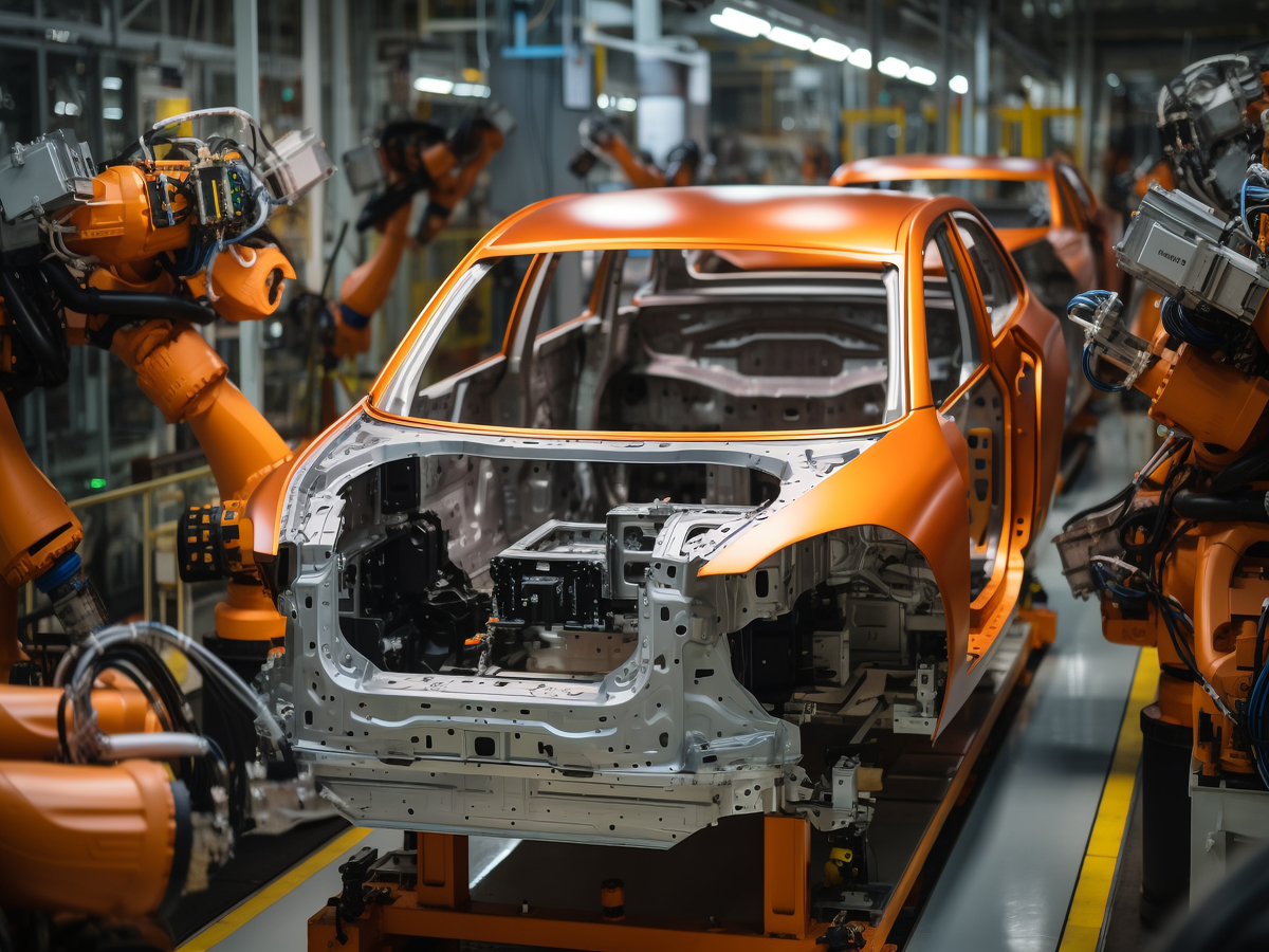
End-Effector Weight
The weight of a custom end-effector contributes to the robot's total payload.
Engineers should evaluate the combined mass of the tooling, workpiece, mounting hardware, and any auxiliary equipment.
A lighter component may improve system flexibility where payload capacity is limited.
Mass Distribution
Two end-effectors with the same total mass may create different mechanical demands if their centers of mass are located differently.
Material selection and component geometry should therefore consider mass distribution as well as overall weight.
Structural Stiffness
Reducing component mass should not compromise the stiffness required for accurate positioning.
Excessive deflection may affect gripping accuracy, tool alignment, or repeatable operation.
The appropriate design balances stiffness, strength, weight, and manufacturing feasibility.
Precision Shafts, Joint Interfaces, and Bearing Fits
Precision shafts and mechanical interfaces are important in robotic motion systems.
Their design must consider the complete assembly rather than isolated dimensional accuracy.
Shaft Diameter and Bearing Fit
The shaft diameter and tolerance must be compatible with the mating bearing or bushing.
A nominal diameter alone is not sufficient to define the required fit.
The design should consider the selected bearing, loading direction, operating temperature, assembly method, and maintenance requirements.
Where ISO limits and fits are used, ISO 286 may be relevant.
The appropriate tolerance class must be determined by the equipment designer.
Concentricity and Runout
For rotating shafts, the relationship between bearing seats, shoulders, and other critical features can influence assembly performance.
Runout and geometric controls should reflect the functional requirements.
Excessive geometric variation may contribute to vibration, uneven loading, or premature wear.
Joint Interfaces
Robotic joint components may require accurately positioned mounting holes, locating features, and mechanical interfaces.
Where the component is part of a critical motion or load-bearing system, additional validation may be required.
Slender Shaft Machining
Slender shafts may deflect during machining due to cutting forces and workholding conditions.
Suitable machining methods, support arrangements, and process planning may be required.
The achievable tolerance depends on geometry, material, tooling, and machine capability.
Robotic Positioning Accuracy and Repeatability
Robotic systems depend on accurate mechanical relationships between components.
However, component machining accuracy and complete robot positioning accuracy are not the same.
A CNC machined component may meet its dimensional requirements while the assembled robot's performance is influenced by other factors.
These may include:
Joint backlash
Bearing clearance
Structural deflection
Thermal expansion
Assembly alignment
Actuator performance
Control system behavior
Load variation
Design engineers should identify which component dimensions directly influence the required system performance.
Locating Features
Precision locating pins, dowel holes, shoulders, and datum surfaces can help establish repeatable assembly positions.
The selected locating arrangement should avoid unnecessary overconstraint.
Tolerance Stack-Up
Dimensional variation across multiple assembled components can influence tool alignment and positioning.
Tolerance stack-up analysis helps determine where tighter controls are necessary and where more economical tolerances may be acceptable.
Thermal Effects
Temperature variation may change component dimensions and assembly relationships.
Where high positioning accuracy is required, thermal expansion should be considered in the mechanical design.
Custom Robotic Gripper and End-Effector Components
Robotic grippers and end-effectors often contain small, complex mechanical components.
These may include gripper fingers, mounting adapters, precision spacers, locating pins, and custom threaded hardware.
Gripper Finger Design
Gripper fingers should be designed according to the workpiece geometry, gripping force, contact conditions, and required positioning accuracy.
Material selection may consider wear, corrosion resistance, stiffness, and weight.
A stainless steel gripper finger may be appropriate for selected applications, but it is not universally preferred.
Tool Mounting Interfaces
Mounting adapters may require controlled flatness, hole position, perpendicularity, and locating features.
The appropriate tolerances depend on the end-effector design and assembly requirements.
Fastening Reliability
Threaded connections should be evaluated for applied loads, vibration, assembly torque, and maintenance conditions.
Suitable locking features or installation procedures may be necessary.
Custom Threaded Adapters and Robotics Fastening Hardware
Robotics applications may require special threaded adapters, studs, sleeves, spacers, and precision mounting components.
CNC machining can support non-standard geometry and controlled dimensional relationships.
Thread Standards
ISO 261 and ISO 965 may be relevant to ISO metric screw threads.
ASME B1.1 covers Unified inch screw threads, including UNC and UNF series.
Metric and Unified inch threads are not directly interchangeable.
Where BSW or BSF threads are specified, their separate British thread standards and geometry must be respected.
A nominal diameter conversion does not establish thread compatibility.
Thread Engagement
Thread engagement should be evaluated according to the applied load, mating material, thread size, and assembly requirements.
A longer thread engagement does not automatically improve the joint if other failure modes govern the design.
Galling and Assembly Reliability
Stainless steel threaded components may experience galling under certain assembly conditions.
Suitable mating materials, lubrication, surface treatments, and installation procedures may reduce the risk.
Vibration and Preload Retention
Where robotic equipment operates under vibration or cyclic loading, the complete joint should be evaluated for preload retention and loosening resistance.
A custom machined thread does not automatically provide vibration resistance.
CNC Machining Processes for Robotics Precision Parts
The appropriate machining process depends on geometry, material, tolerance requirements, and production quantity.
CNC Turning
CNC turning is suitable for rotationally symmetric components such as shafts, pins, bushings, sleeves, threaded adapters, and cylindrical spacers.
Typical operations include facing, external turning, boring, drilling, grooving, and threading.
Workholding, tool access, cutting conditions, and surface finish requirements influence the process plan.
Swiss-Type CNC Machining
Swiss-type machining may be advantageous for small-diameter, slender precision components.
The guide-bushing arrangement can support the workpiece near the cutting area, helping control deflection in suitable applications.
However, Swiss-type machining is not automatically the most economical choice for every small component.
Part geometry, material, setup complexity, cycle time, and production quantity influence process selection.
CNC Milling
CNC milling may be suitable for robotic mounting blocks, gripper components, adapters, housings, and tooling interfaces.
Datum selection and fixture stability are important where positional relationships between features affect assembly.
Drilling, Tapping, and Threading
Machined components may require internal threads, external threads, precision holes, and mounting features.
Thread quality depends on material properties, tooling, cutting conditions, and inspection methods.
For stainless steel, machining plans should account for tool wear and work hardening.
Combined Turning and Milling
Turn-mill machining can combine rotational and non-rotational operations.
For suitable components, reducing the number of setups may improve relationships between critical features and reduce handling.
The benefit depends on machine configuration, tooling, part complexity, and production volume.
Design for Manufacturability in Robotics CNC Components
Design for Manufacturability (DFM) helps align engineering requirements with practical machining processes.
Early DFM evaluation can reduce unnecessary complexity, improve production repeatability, and lower total component cost.
Tolerance Allocation
Not every dimension requires the same tolerance.
Critical-to-function features should receive appropriate dimensional and geometric controls.
Non-critical dimensions may permit more economical tolerances.
Unnecessarily tight tolerances can increase machining time, inspection effort, scrap risk, and cost.
Thin Walls and Machining Stability
Thin-walled components may deform during machining due to cutting forces, clamping pressure, or residual stress.
Special workholding or controlled machining sequences may be required.
The achievable tolerance depends on material, geometry, tooling, and process stability.
Deep Holes and Tool Accessibility
Deep or narrow holes may require specialized tooling and additional machining time.
Engineers should consider tool reach, chip evacuation, coolant access, and measurement requirements.
Where design flexibility exists, simplifying difficult internal features may reduce cost.
Surface Finish and Functional Requirements
Surface finish should be specified according to component function.
A bearing interface, sealing surface, gripper contact surface, and general mounting feature may require different surface conditions.
Specifying unnecessarily fine surface finish across an entire component can increase machining cost without improving performance.
GD&T and Precision Robotic Assembly
Geometric Dimensioning and Tolerancing (GD&T) helps define relationships between critical features.
Depending on the drawing system, ASME Y14.5 or ISO 1101 may be applicable.
Relevant controls may include position, flatness, perpendicularity, parallelism, runout, and profile.
Datum selection should reflect how the component is located and assembled.
For example, a robotic mounting adapter may require controlled relationships between locating features, mounting holes, and reference surfaces.
A precision shaft may require appropriate controls between bearing seats and other functional features.
GD&T should support functional assembly and inspection rather than introducing unnecessary manufacturing complexity.
Precision, Repeatability, and Production Stability
For robotics OEM manufacturing, a successful CNC machining process must produce consistent results across the required production quantity.
A dimensionally accurate prototype does not automatically establish production capability.
Important process controls may include:
Approved CNC programs
Controlled workholding
Tool-life management
Material consistency
Cutting parameters
In-process inspection
Final dimensional verification
Documented drawing revisions
Appropriate handling and packaging
Production managers should evaluate machining cycle time, setup requirements, inspection frequency, scrap risk, and process consistency.
The appropriate manufacturing approach depends on component complexity, required tolerances, and purchasing volume.
Quality Control for Custom CNC Robotics Parts
Inspection planning should follow the approved drawing and the component's functional requirements.
Depending on the project, inspection may include dimensional measurement, thread inspection, material verification, hardness testing, surface-finish measurement, and functional checks.
Dimensional Inspection
Critical dimensions may be verified using suitable micrometers, calipers, bore gauges, height gauges, or coordinate measuring equipment.
The measurement method should provide sufficient capability for the specified tolerance.
Thread Inspection
Threaded components may require appropriate thread gauges or other verification methods.
The inspection method should follow the specified thread standard and customer requirements.
Material Verification
Customers may require material documentation or additional verification of the specified stainless steel grade.
The required documentation should be agreed upon during quotation.
Hardness and Heat-Treatment Verification
Where hardness or heat-treatment condition is functionally important, the drawing should define the applicable requirements.
Any required testing or documentation should be confirmed before production.
Surface Finish Verification
Where surface finish is functionally important, the drawing should define the relevant parameters and inspection requirements.
The measurement method should be suitable for the specified surface and geometry.
First-Article and Production Inspection
OEM projects may require first-article inspection or other customer-defined approval activities before repeat production.
Inspection frequency, reporting, traceability, and approval requirements should be established according to the purchasing specification.
Any required certification, testing, or documentation must be confirmed for the specific project.
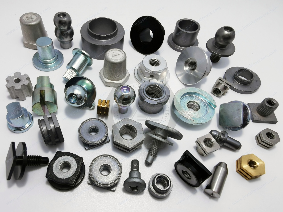
International Standards and Robotics Application Requirements
Robotics projects may involve technical requirements beyond those normally applied to general industrial mechanical components.
The applicable standards depend on the equipment type, component function, and customer specification.
ISO Metric Threads
ISO 261 provides relevant metric screw thread series information.
ISO 965 addresses tolerance requirements for ISO general-purpose metric screw threads.
Metric thread designations and tolerance classes should be defined in the approved drawing.
ASME Unified Inch Threads
ASME B1.1 covers Unified inch screw threads, including UNC and UNF series.
These thread systems may be relevant to North American robotics equipment designs.
Metric and Unified inch threads are not directly interchangeable.
ISO 286 Limits and Fits
ISO 286 may be relevant where standardized limits and fits are used for shafts and holes.
The appropriate fit depends on the component function and mating assembly.
Robotics Safety Requirements
Industrial robot systems may be subject to applicable safety standards, including the ISO 10218 series.
However, these requirements do not automatically apply to every isolated CNC machined component.
Their relevance depends on the component's function and the complete robotic system.
General machining capability does not establish compliance with robotic safety requirements.
From Prototype Development to Repeat OEM Production
CNC machining can support robotics component development because geometry and machining programs can be revised as the design evolves.
However, transitioning from prototypes to repeated production requires additional process planning.
Engineering Drawing and CAD Review
The initial review should identify material, geometry, critical tolerances, functional interfaces, and inspection requirements.
Potential manufacturing risks should be clarified before machining begins.
Material and Process Selection
The material and machining process should be selected according to functional requirements, part geometry, quantity, and cost.
Alternative manufacturing approaches may be considered where technically appropriate.
Prototype and First-Article Machining
Initial parts can be evaluated for dimensional accuracy, assembly fit, surface condition, and manufacturing feasibility.
Any design or process changes should be documented.
Process Optimization
After design approval, machining operations may be optimized for cycle time, tooling, repeatability, and inspection efficiency.
The appropriate optimization depends on the required production quantity.
Repeat Production and Final Inspection
Repeat production should follow the approved drawing revision and agreed quality requirements.
Inspection, packaging, and delivery arrangements should be established according to the customer's purchasing specification.
CNC Machining vs. Standard Robotics Fasteners
Custom CNC machining provides flexibility for non-standard geometry and precision mechanical interfaces.
However, not every robotics component requires CNC machining.
Standard screws, nuts, washers, studs, pins, bushings, and other fastening components may offer a more economical solution for suitable applications.
When CNC Machining May Be Appropriate
CNC machining may be justified where the design requires:
Non-standard geometry
Precision concentric features
Special threaded interfaces
Controlled locating features
Custom mounting blocks
Specific material requirements
Multiple machined features
Drawing-based dimensional relationships
When Standard Fasteners May Be More Economical
Standard fastening components may be preferable where the required function can be achieved without custom machining.
For example, a standard threaded stud or precision dowel pin may provide an efficient solution for a compatible mechanical assembly.
However, standard components must still meet the required material, dimensional, mechanical, and environmental specifications.
The appropriate solution should be selected according to engineering compatibility and total installed cost.
OEM Supplier Development and Procurement Considerations
For robotics manufacturers, sourcing custom machined components requires both technical qualification and commercial evaluation.
Supplier selection should consider drawing conformity, material compatibility, machining feasibility, process consistency, quality expectations, and supply planning.
Drawing-Based Supplier Evaluation
A technically complete RFQ should include the approved drawing, CAD model, material specification, tolerances, surface finish, and required quantity.
Where an existing component is being transferred from another supplier, the latest drawing revision and critical functional characteristics should be identified.
Alternative Material and Process Evaluation
A proposed alternative material or machining process should be reviewed against the original engineering requirements.
Material substitution should not be approved solely because two grades have similar nominal properties.
Corrosion resistance, strength, stiffness, weight, fatigue behavior, wear characteristics, and application requirements must be considered.
Any proposed change should be approved by the customer's engineering team.
MOQ, Lead Time, and Volume Purchasing
Purchasing teams should provide estimated order quantities, annual demand, target delivery schedules, and packaging requirements.
For custom CNC components, setup complexity, material availability, tooling, inspection requirements, and production volume can influence MOQ and lead time.
Commercial feasibility should be confirmed for each project.
Total Cost Optimization
The total cost of a machined robotics component depends on several factors:
Material grade and stock form
Part geometry
Machining cycle time
Number of setups
Tooling and tool wear
Dimensional tolerances
Surface finish
Secondary operations
Inspection requirements
Scrap and rework
Order quantity
Delivery schedule
Early collaboration between engineering and procurement teams can help identify cost-saving opportunities without compromising functional requirements.
Practical RFQ Checklist for Robotics CNC Components
A complete RFQ helps reduce technical clarification and supports accurate quotation.
Useful information includes:
2D engineering drawing
3D CAD model, if available
Component application and function
Stainless steel grade and material specification
Heat-treatment condition, if applicable
Critical dimensional tolerances
GD&T requirements
Thread specifications
Surface finish requirements
Coating or secondary processing requirements
Payload, weight, and inertia requirements
Mechanical loading and wear requirements
Corrosion and operating environment
Inspection and documentation requirements
Prototype or sample quantity
Estimated production order quantity
Annual demand forecast
Packaging requirements
Delivery destination and target schedule
Where the component is intended for a safety-critical or heavily loaded robotic application, the required qualification, validation, and approval procedures should be explicitly identified.
Why Work with JUXIN FASTENERS for Robotics CNC Machining Projects?
JUXIN FASTENERS supports drawing-based inquiries for precision machined components and industrial fastening hardware used in OEM manufacturing.
Relevant machining inquiries include:
Stainless steel CNC turned parts
Robotics precision shafts and pins
CNC machined bushings and sleeves
Custom threaded adapters
Robotic gripper components
End-effector mounting hardware
Precision tooling interfaces
Robot mounting blocks and adapters
Drawing-based robotic mechanical parts
OEM repeat purchasing requirements
Our approach emphasizes clear technical communication and evaluation of the customer's drawings, materials, tolerances, manufacturing requirements, and purchasing quantities.
For design and mechanical engineers, the priority is functional geometry, material suitability, and dimensional accuracy.
For manufacturing engineers and production managers, the priority includes process repeatability, machining efficiency, inspection stability, and consistent production quality.
For procurement and supply chain teams, the priority includes technical conformity, commercial feasibility, cost control, delivery planning, and long-term supplier evaluation.
Manufacturing feasibility, achievable tolerances, MOQ, lead time, testing, and documentation requirements are confirmed according to the specific inquiry.
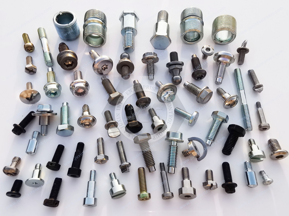
Request a Quote for Stainless Steel CNC Machining and Robotics Components
Are you developing a new robotic mechanical component, sourcing custom stainless steel CNC machined parts, or evaluating an alternative supplier for repeat OEM production?
JUXIN FASTENERS welcomes technical and commercial inquiries from robotics manufacturers, automation equipment suppliers, engineering teams, production departments, and industrial procurement organizations.
Send us your 2D drawings, 3D CAD models, material specifications, critical tolerances, surface finish requirements, and estimated purchasing quantities.
We can review your project requirements and discuss suitable machining approaches, technical clarification, and RFQ arrangements.
JUXIN FASTENERS
Website: https://www.juxinfasteners.com
Email: info@juxinfasteners.com
RFQ: Robotics CNC Machining | Stainless Steel Precision Parts | OEM Custom Components
Contact Us
Tel.:
+86 020 8621 0320
+86 020 3121 6067
E-mail:
Technical Support:
Navigation
SEND INQUIREY



