
Call Us
+86 136 6007 9809
Call Us
+86 136 6007 9809

Sep. 25, 2026
Plastic housings reduce weight, enable complex molded geometry, simplify part consolidation, and can lower manufacturing cost across automotive electronics,
AI server equipment, medical devices, telecommunications systems, industrial controls, appliances, and power electronics.
But creating a durable threaded joint directly in plastic can be challenging.
A screw repeatedly driven into a molded plastic boss can gradually damage the polymer thread.
High tightening loads can strip the internal plastic thread, while poorly designed bosses can crack during assembly.
Over time, polymer creep, stress relaxation, moisture absorption, temperature cycling, and repeated service access can further change joint behavior.
Thread inserts for plastics provide another engineering option.
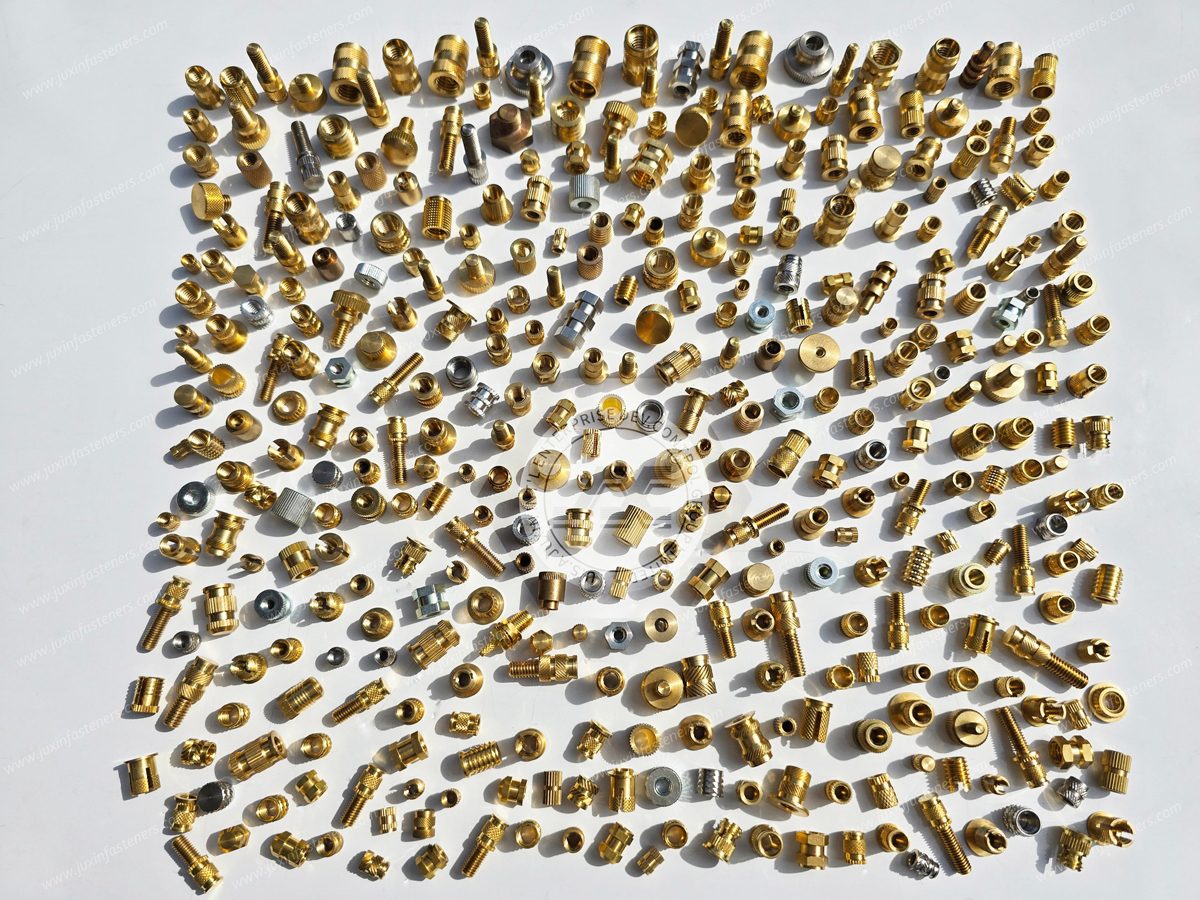
Brass, stainless steel, and other metal threaded inserts can create a reusable female metal thread inside a molded polymer component. Depending on the insert and application, installation methods can include:
heat insertion
ultrasonic insertion
press-in installation
molded-in installation
However, the insert itself is only one part of the system.
Reliable performance depends on the relationship between:
insert geometry + plastic resin + boss geometry + molded-hole dimensions + installation process + screw joint + service environment
Also searched as brass inserts for plastics, heat stake threaded inserts, heat set inserts for plastic,
ultrasonic threaded inserts, molded-in threaded inserts, knurled brass inserts, threaded inserts for thermoplastics,
stainless steel inserts for plastic, and plastic threaded inserts, these components should be selected according to the complete assembly rather than thread size alone.
A practical engineering path is:
Application → polymer → service conditions → thread requirement → insert geometry
→ boss design → installation method → process validation → pull-out and torque-out testing → production control
Direct screw engagement in plastic can be appropriate for many applications.
A metal insert becomes particularly useful when the assembly requires:
repeated assembly and disassembly
higher tightening loads
durable machine-screw threads
service access
dimensional consistency
improved resistance to thread wear
replaceable covers or modules
standardized metric or Unified threads
The decision should therefore begin with the joint requirement.
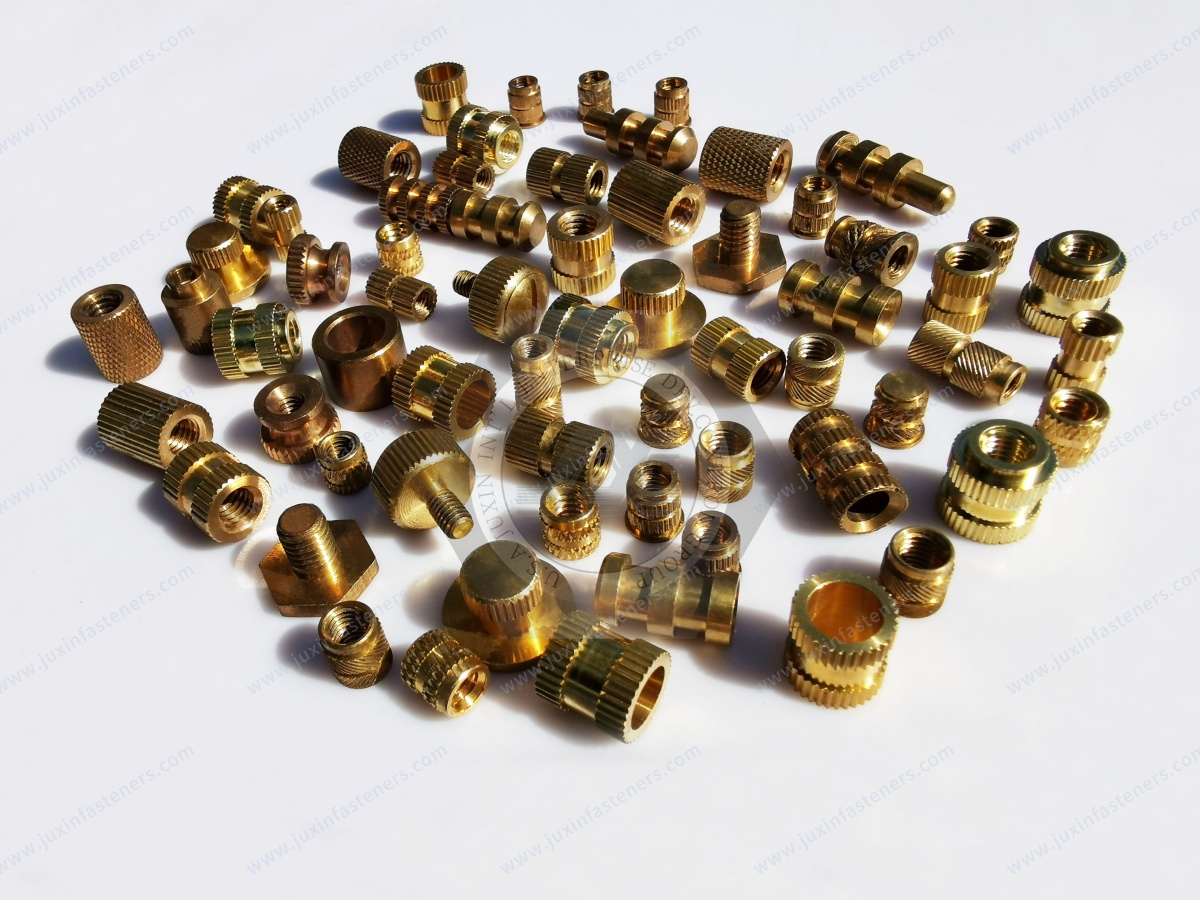
Not every plastic assembly benefits from a metal insert.
Direct fastening into plastic may remain appropriate when:
the assembly is installed only once or a limited number of times
required clamp load is modest
service access is not required
component cost is highly sensitive
the polymer and screw system have already been validated
sufficient boss geometry is available
Adding an insert introduces:
component cost
installation equipment
process control
additional manufacturing steps
The correct question is not:
“Are inserts stronger than plastic threads?”
It is:
“Does this assembly need the performance and serviceability provided by a metal threaded interface?”
A threaded insert cannot be selected correctly from thread size alone.
An M4 insert that performs well in one PA66 housing may perform differently in another application using:
ABS
polycarbonate
PBT
glass-filled nylon
PEEK
a different boss diameter
a different molded-hole tolerance
a different installation process
For this reason, insert performance should be evaluated in the customer's actual or representative polymer and boss geometry.
Thread inserts use engineered external geometry to transfer load into the surrounding polymer.
Depending on the insert design, this geometry may include:
straight knurls
diamond knurls
helical knurls
opposing knurl bands
grooves
undercuts
ribs
barbs
flanges
Different features can contribute differently to rotational and axial retention.
When a screw is tightened into the insert, the insert experiences torque.
External features mechanically engage the surrounding polymer and help resist rotation.
Performance can depend on:
insert diameter
knurl geometry
insert length
polymer
boss geometry
hole dimensions
installation quality
There is no universal knurl geometry that provides the highest torque-out resistance in every polymer.
Axial load attempts to pull the insert from the boss.
Retention features such as:
undercuts
grooves
knurls
shoulders
can create mechanical interlocking with the polymer.
Pull-out performance also depends on how effectively the polymer flows around these features during installation.
Some thermally installed inserts use opposing helical knurl directions.
This geometry can provide mechanical resistance to rotation in either direction after the polymer has flowed around the insert and solidified.
However, opposing helical knurls are one insert architecture rather than a universal requirement.
Other insert designs can achieve effective retention through different geometries.
Circumferential grooves or undercuts can provide space for displaced polymer.
During thermal or ultrasonic installation, softened polymer may flow into these regions and create axial mechanical interlock after cooling.
The effectiveness depends on:
polymer flow
insertion temperature
insertion speed
hole size
insert geometry
A controlled lead-in can help:
align the insert
enter the molded hole
reduce cocked installation
improve process repeatability
The required pilot geometry depends on the insert and installation method.
Brass is widely used for threaded inserts because it offers a useful combination of:
machinability
corrosion behavior for many environments
thermal conductivity
dimensional precision
knurl-forming capability
Its thermal conductivity can be advantageous in heat-insertion processes because energy can transfer through the insert into the surrounding thermoplastic.
However, brass alloy selection should follow:
mechanical requirements
regulatory requirements
customer material specifications
environmental requirements
Do not assume that all commonly machined brass alloys satisfy every customer's restricted-substance requirement.
If lead content is controlled, the RFQ should specify the applicable:
material requirement
customer specification
regulatory requirement
Where necessary, alternative brass compositions or other materials can be evaluated.
Stainless steel inserts may be considered where the application requires characteristics such as:
corrosion resistance
material compatibility
customer-specific material requirements
elevated-temperature performance
specific environmental resistance
Potential applications can include:
medical equipment
food-service equipment
laboratory equipment
outdoor equipment
industrial machinery
Material selection should be based on the actual service environment.
Neither material is universally superior.
| Engineering Factor | Brass Inserts | Stainless Steel Inserts |
|---|---|---|
| Machinability | Generally favorable | More demanding |
| Thermal conductivity | Relatively high | Lower than brass |
| Heat insertion | Often well suited | Process may require different thermal settings |
| Corrosion behavior | Application dependent | Often selected for demanding environments |
| Material compliance | Alloy must be specified | Grade must be specified |
| Cost | Application and geometry dependent | Often higher, but project dependent |
| Magnetic behavior | Generally non-ferromagnetic | Depends on stainless grade and processing |
| Application selection | Broad industrial use | Often selected where environment or specification requires it |
The final choice should follow the assembly requirements.
Heat insertion uses controlled thermal energy to soften thermoplastic around the insert.
A heated installation tip transfers heat into the insert while controlled axial force moves it into the molded hole.
The process generally follows:
Position insert → apply controlled heat → polymer softens → insert enters boss
→ polymer flows around retention features → insert reaches controlled depth → polymer cools and solidifies
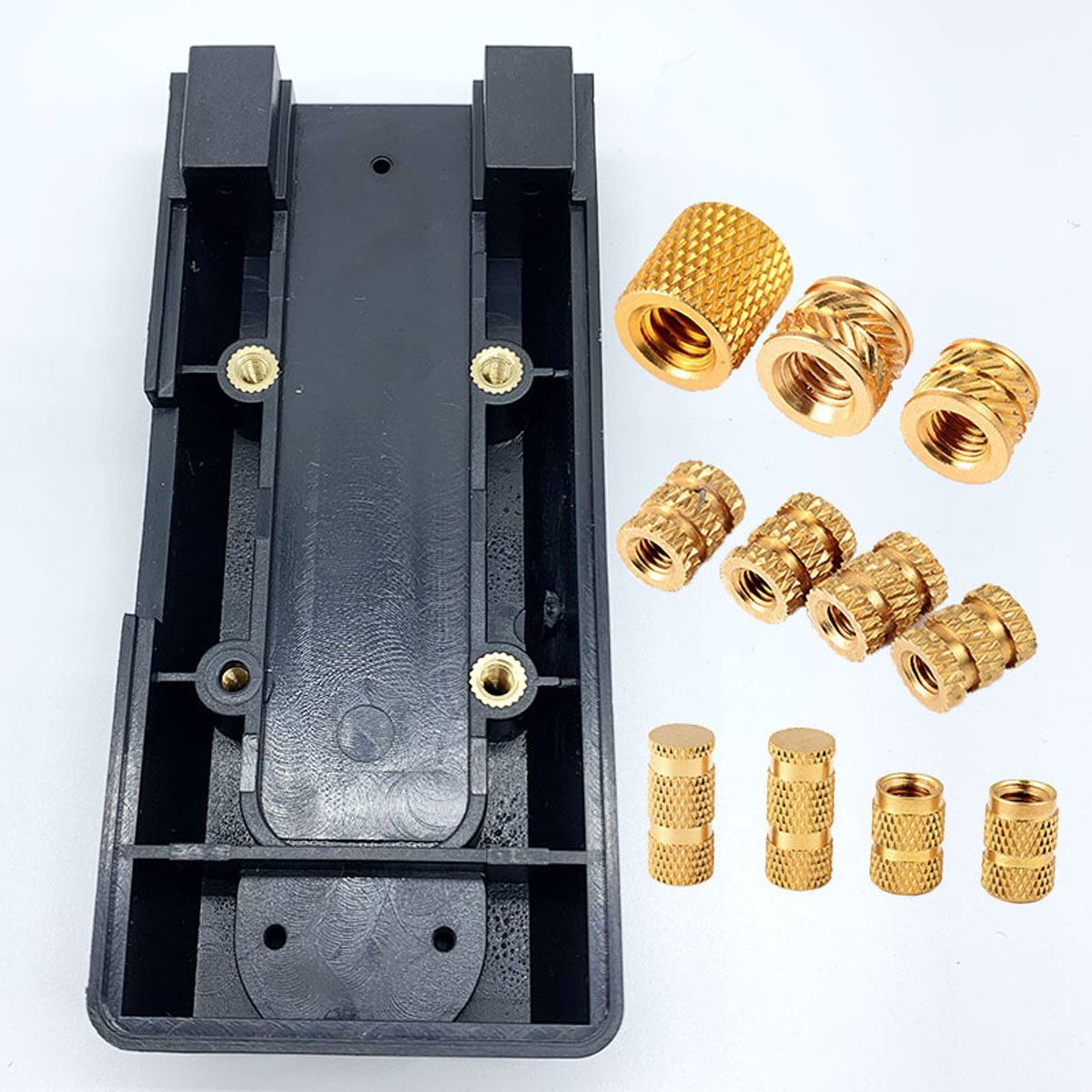
Potential advantages include:
controlled polymer flow
relatively simple tooling
low acoustic noise
compatibility with many thermoplastic applications
potential for automated production
However, performance depends on a qualified process window.
Important variables can include:
tip temperature
insertion speed
insertion force
dwell time
insert temperature
boss dimensions
polymer
filler content
insert geometry
cooling time
These parameters should be developed experimentally for the actual component.
Excessive heat can create:
polymer degradation
excessive flash
boss deformation
sink
poor insert position
enlarged holes
reduced retention
Insufficient heat can create:
high insertion force
boss cracking
incomplete polymer flow
poor seating
A qualified process window is more useful than a single generic installation temperature.
Ultrasonic insertion uses high-frequency mechanical vibration to generate localized heating at the insert/polymer interface.
The softened polymer flows around the insert retention features as controlled pressure moves the insert into position.
Potential advantages can include:
short cycle times
localized heating
automation potential
high production throughput
But ultrasonic insertion requires appropriate process development.
Important parameters can include:
horn design
frequency
amplitude
pressure
trigger conditions
insertion depth
energy
time
polymer
boss geometry
insert geometry
The correct settings depend on the actual assembly.
Polymer structure affects thermal and ultrasonic insertion behavior.
Amorphous polymers and semi-crystalline polymers can have different:
softening behavior
melt characteristics
energy response
shrinkage
processing windows
Therefore, installation method should be qualified for the actual resin rather than selected from a simplified material-category rule.
| Engineering Factor | Heat Insertion | Ultrasonic Insertion |
|---|---|---|
| Energy source | Conductive heating | High-frequency mechanical vibration |
| Polymer heating | Controlled local thermal softening | Localized frictional / viscoelastic heating |
| Cycle time | Process dependent | Can be short when optimized |
| Equipment | Heated installation system | Ultrasonic generator, horn and tooling |
| Noise | Generally low | Acoustic management may be required |
| Filled polymers | Requires qualification | Requires qualification |
| Automation | Suitable | Suitable |
| Process sensitivity | Temperature, force, time, speed | Amplitude, energy, pressure, time, horn design |
Neither method should be declared universally superior.
Press-in inserts rely primarily on mechanical interference rather than intentionally melting the surrounding polymer.
They may use:
barbs
knurls
splines
serrations
Press-in installation can simplify production because dedicated heating equipment may not be required.
However, the insertion force creates stress in the boss.
Potential applications include polymers and joint designs where:
the resin can tolerate the installation strain
boss geometry provides adequate support
required retention is achievable
thermal equipment is undesirable
The insert and boss should be tested together.
Poorly matched interference can contribute to:
boss cracking
stress whitening
excessive residual stress
weak retention
dimensional distortion
The hole diameter and insert geometry should therefore be validated for the actual resin.
Molded-in inserts are positioned inside the mold before polymer injection.
The plastic then forms around the insert during the molding cycle.
Potential advantages can include:
elimination of a separate post-molding insertion operation
strong geometric integration
ability to use specialized insert geometry
Potential challenges can include:
insert loading
insert positioning
molding-cycle complexity
tooling design
insert movement during molding
polymer contamination of threads
automation requirements
Retention depends on:
insert geometry
polymer
surrounding wall structure
molding conditions
load direction
A properly designed post-mold thermal insert can outperform a poorly designed molded-in insert.
Installation method should therefore be selected based on manufacturing and joint requirements rather than assumed strength ranking.
A useful decision path is:
If yes, heat or ultrasonic insertion may be possible depending on the resin and design.
If yes, heat, ultrasonic, or press-in methods may be considered.
If yes, molded-in installation may be appropriate.
If yes, evaluate automation, cycle time, insert feeding, tooling, and process monitoring.
If yes, boss stress and installation behavior require additional validation.
If yes, evaluate sink, read-through, distortion, and thermal effects.
The boss is not merely a hole for the insert.
It is the structural element that transfers load between:
metal insert → polymer → surrounding molded component
Its geometry should therefore be designed together with the insert.
Important dimensions can include:
molded-hole diameter
hole depth
boss outside diameter
boss height
wall thickness
draft
fillet radius
distance to adjacent walls
distance to cosmetic surfaces
The correct dimensions depend on the insert and resin.
Generic boss-diameter ratios can be useful during early concept design.
They should not replace the insert manufacturer's or validated application-specific design recommendations.
Required boss wall thickness depends on:
polymer
filler
insert diameter
insert geometry
installation method
load
molded-part geometry
A fixed rule such as W ≥ 0.5 × hole diameter should not be applied universally.
Hole diameter is one of the most critical variables.
If the hole is too small:
insertion force can increase
boss stress can increase
cracking may occur
excessive polymer may be displaced
If the hole is too large:
insufficient polymer may engage the retention geometry
torque-out may decrease
pull-out may decrease
The target hole should be defined for the specific insert and resin.
The hole must accommodate:
insert length
installation depth
displaced polymer
screw engagement requirements
Blind-hole designs must also prevent the assembly screw from bottoming before the joint is clamped.
Do not automatically add the same fixed depth allowance to every insert.
Molded holes may require draft for tooling release.
But excessive taper can create a large difference between the entrance and bottom diameters.
That can change:
insertion force
polymer flow
retention
insert alignment
Draft should therefore be coordinated among:
mold designer
insert supplier
manufacturing engineer
rather than assigned one universal maximum angle.
Increasing boss diameter can provide more polymer around the insert.
However, excessive local wall thickness can create molding problems such as:
sink marks
long cooling time
dimensional variation
cosmetic read-through
Boss design therefore involves both structural and molding considerations.
The base of a boss can experience stress from:
screw tightening
pull-out loading
side loading
installation
Appropriate fillets, ribs, or surrounding structural support can help distribute load.
The design should also avoid creating excessive molded thickness that produces sink or warpage.
Threaded insert performance is strongly influenced by the polymer.
Common engineering plastics include:
ABS
PC
PC/ABS
PA6
PA66
PBT
POM
PPS
PEEK
polypropylene
other engineering thermoplastics
Each behaves differently during installation and service.
ABS is commonly used in:
electronics housings
equipment covers
appliances
control panels
Its insertion process should be optimized for the specific grade and molded geometry.
PC is used where applications may require:
impact resistance
dimensional performance
transparent or engineered housings
Thermal history and molded stress should be considered during insert installation.
Nylon is widely used in automotive and industrial components.
Its behavior differs from ABS or PC because nylon can absorb moisture from the environment.
This matters both during testing and service.
PA6 and PA66 properties can change as moisture content changes.
Moisture can influence:
stiffness
ductility
dimensions
creep
retention behavior
An insert tested in very dry molded nylon may not behave identically after the component reaches an equilibrium moisture condition in service.
For critical applications, validation should define the relevant polymer conditioning state.
Glass fiber can increase properties such as stiffness and dimensional stability, but it also changes how the polymer flows and responds during insert installation.
Important factors include:
fiber percentage
fiber orientation
molded-hole quality
local boss geometry
installation process
Do not assume that one insertion method is automatically superior for all glass-filled nylon grades.
PBT is widely used in:
automotive electrical components
connectors
electrical housings
industrial components
Filled and unfilled PBT can behave differently during insert installation.
The insert and boss should be validated using the production resin.
PEEK and other high-performance polymers may be used in demanding applications involving:
elevated temperature
chemical exposure
aerospace equipment
semiconductor equipment
medical equipment
Their higher material cost and processing characteristics make insert selection and process validation particularly important.
A base polymer name alone may not sufficiently define the material.
For example:
PA66
and
PA66 GF30
should not automatically be treated as the same insert substrate.
Fillers can affect:
stiffness
shrinkage
thermal conductivity
creep
insertion behavior
cracking resistance
retention
The exact production material should be included in the RFQ.
Plastic is viscoelastic.
Under sustained load, it can deform over time.
This is known as creep.
The joint can also experience stress relaxation, reducing the force maintained by the polymer over time.
A strong initial pull-out test does not automatically prove long-term joint performance.
Service conditions may include:
constant clamp load
elevated temperature
thermal cycling
vibration
moisture
These can change the polymer surrounding the insert.
For long-life assemblies, engineers should evaluate the actual service conditions rather than relying only on room-temperature installation tests.
A threaded insert can remain firmly retained in the boss while the bolted joint loses clamp load because the surrounding plastic creeps.
This means two different questions must be answered:
Will the insert stay in the plastic?
Will the assembled joint maintain the required clamp load?
These are related but not identical engineering problems.
The mating screw should engage sufficient insert thread for the application without bottoming in a blind insert or boss.
The required engagement depends on:
screw material
insert material
thread size
load
insert length
Do not use one universal thread-engagement multiplier for every application.
Some threaded inserts include a flange.
Potential reasons include:
installation stop
larger bearing surface
pull-through resistance
position control
But a flange also changes:
packaging envelope
surface appearance
boss design
installation tooling
The correct geometry depends on the assembly.
Some insert geometries are symmetrical and can simplify automated feeding because either end may be inserted.
Other designs are directional because they include:
tapered pilot
flange
asymmetric knurl pattern
Production automation requirements should be considered during component selection.
Understanding failure modes is useful during both design and supplier qualification.
Possible causes include:
oversized molded hole
insufficient polymer engagement
unsuitable knurl geometry
poor installation
excessive tightening torque
Possible causes include:
insufficient engagement length
weak surrounding boss
oversized hole
inadequate undercut engagement
excessive axial load
Possible causes include:
hole too small
insufficient boss wall
brittle polymer
excessive insertion force
poor process settings
molded residual stress
Possible causes include:
inconsistent installation depth
poor fixture control
variable hole geometry
incorrect process endpoint
Possible causes include:
excessive heat
excessive polymer displacement
poor insert geometry
unsuitable process settings
Possible causes can include:
excessive screw torque
long-term creep
environmental stress
thermal cycling
insufficient surrounding structure
Failure analysis should distinguish installation failure from service failure.
Pull-out testing measures the axial force required to remove the insert from the plastic boss under the specified test configuration.
Results depend strongly on:
insert geometry
boss geometry
resin
conditioning
installation process
test fixture
loading direction
Therefore, pull-out values from unrelated materials should not be treated as universal product ratings.
Torque-out testing evaluates resistance to insert rotation within the plastic.
It can help verify:
knurl engagement
hole sizing
installation quality
polymer interaction
Acceptance criteria should be based on the application.
For meaningful qualification, samples should ideally use the customer's actual production resin or a properly controlled representative material.
Changing:
resin grade
glass content
moisture state
molding condition
can change the result.
A strong insert design can still fail if the production process is unstable.
Qualification should therefore evaluate:
insertion depth
perpendicularity
temperature or ultrasonic settings
force
cycle time
boss damage
pull-out
torque-out
The acceptable process window should be established before mass production.
Depending on production volume and risk, process monitoring may include:
temperature
insertion depth
insertion time
force
energy
displacement
The appropriate controls depend on the installation system.
AI server and cooling equipment increasingly use engineered polymer components in:
fan modules
airflow shrouds
cable-management parts
handles
ducts
cooling-system components
Threaded inserts can create durable serviceable mounting points in these plastic components.
High-density servers may require fan modules and airflow components to be removed during service.
A reusable metal thread can reduce wear compared with repeatedly driving a machine screw directly into a molded plastic thread.
Relevant design factors include:
insert retention
boss packaging
vibration
repeated maintenance
installation automation
Polymer components can also appear in:
hose guides
covers
control housings
cable-management components
pump or sensor enclosures
Material compatibility should be evaluated against the actual thermal and chemical environment.
Automotive plastic components can use threaded inserts in:
BMS housings
ECU housings
lighting assemblies
charge-port components
sensor housings
cockpit electronics
interior modules
Applications can involve:
vibration
temperature cycling
moisture
repeated service
automated assembly
The insert should be qualified against the actual OEM component specification.
Polymer covers and electronics housings may require reliable threaded interfaces for:
covers
brackets
sensors
electrical modules
Do not assign a universal temperature range or pull-out requirement to every EV application.
Requirements should come from the actual component environment.
Plastic telecommunications enclosures can use inserts in:
junction boxes
antenna equipment
network enclosures
fiber hardware
outdoor electronics
Important factors can include:
UV exposure
moisture
thermal cycling
repeated field service
corrosion of the insert material
The polymer and metal should be selected as a system.
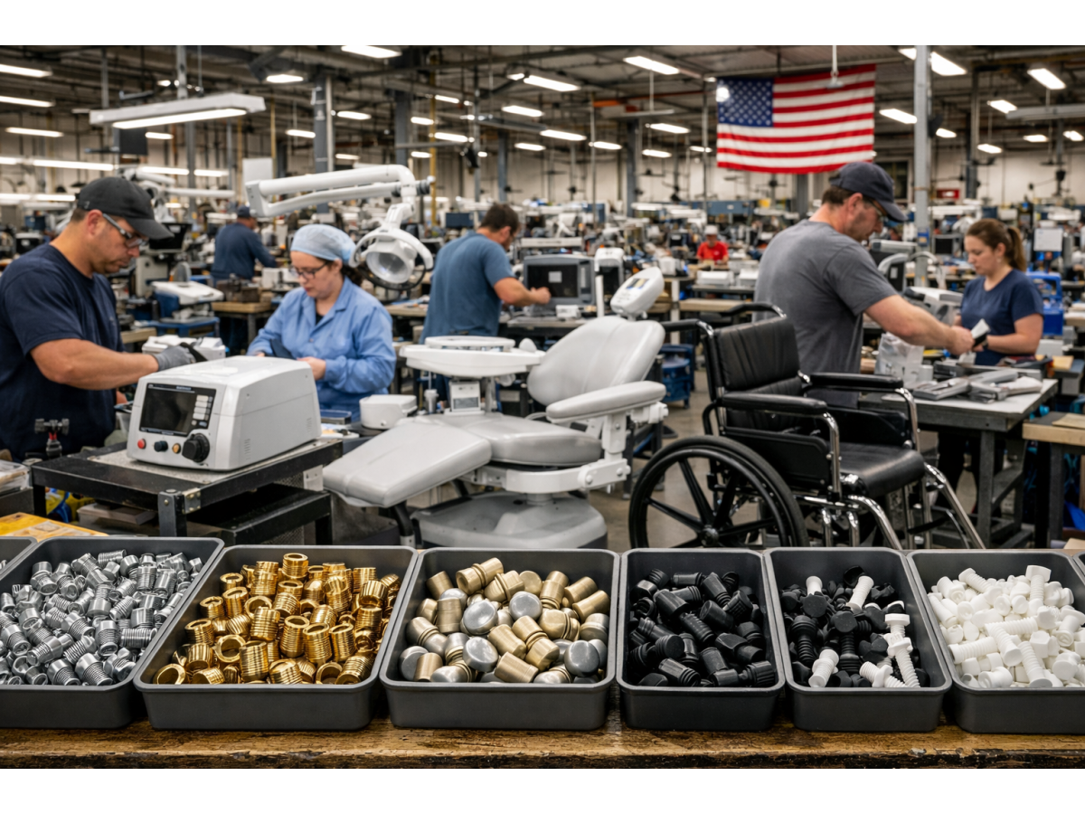
Threaded inserts may be used in:
diagnostic equipment housings
laboratory instruments
monitor enclosures
equipment carts
fluid-management equipment
Potential requirements can include:
corrosion resistance
cleaning-agent compatibility
repeated maintenance
material restrictions
traceability
Material suitability should be defined by the customer application rather than inferred from the words “medical grade.”
Plastic housings are common in:
power supplies
control electronics
inverters
chargers
electrical modules
Thread inserts can provide reusable mounting points for:
covers
circuit-board brackets
cable hardware
service panels
Where the insert has an electrical function, conductivity and grounding requirements should be specified separately.
Industrial equipment can use threaded inserts in:
sensor housings
control boxes
covers
operator interfaces
lightweight polymer components
Applications may involve frequent maintenance and vibration.
Repeated assembly requirements can make metal inserts particularly useful.
Appliances can contain plastic housings requiring durable service access.
Applications include:
control panels
motor housings
covers
handles
equipment frames
The insert selection should consider:
production volume
automation
cost
service cycles
cosmetic surfaces
HVAC equipment may use polymer components in:
control housings
fan assemblies
covers
sensor mounts
Potential requirements include:
temperature
humidity
condensation
repeated maintenance
A threaded insert is one of several possible solutions.
Other options can include:
thread-forming screws for plastic
molded plastic threads
captive nuts
overmolded hardware
snap-fit joints
plastic clips
Selection should consider:
assembly cycles
required clamp load
serviceability
production cost
available space
polymer behavior
Using metal inserts everywhere can unnecessarily increase:
part count
assembly cost
tooling
process complexity
Using direct plastic threads everywhere can create reliability problems in serviceable or highly loaded joints.
The best architecture can use different fastening methods within the same product according to joint function.
Procurement teams may need to qualify an alternative source for an existing threaded insert.
The evaluation should not stop at:
thread size
overall length
outside diameter
Two inserts with similar envelope dimensions can have different retention behavior.
Review:
internal thread
insert length
outer diameter
pilot geometry
knurl geometry
knurl direction
undercuts
flange
material
installation method
boss dimensions
The replacement should be evaluated in the actual assembly.
A second-source insert does not necessarily need identical external knurl geometry if the customer's requirement is functional rather than exact dimensional interchangeability.
The important question may be whether it satisfies:
installation
pull-out
torque-out
boss integrity
dimensional envelope
Where exact geometry is required by the controlled drawing, that requirement should be followed.
If the original drawing is unavailable, a physical insert sample can support evaluation of:
dimensions
thread
material
external geometry
However, a sample alone may not reveal:
material specification
proprietary tolerances
performance criteria
installation settings
Unknown requirements should be identified rather than guessed.
A second-source sample program can include:
dimensional inspection
thread inspection
material verification where required
installation trials
pull-out testing
torque-out testing
assembly trials
For critical applications, the customer's production resin and representative molded bosses should be used.
For thread inserts for plastics, brass inserts for plastics, heat set inserts, ultrasonic threaded inserts,
stainless steel inserts for plastic, custom threaded inserts, or second-source plastic inserts, provide as much of the following information as possible:
2D insert drawing
3D STEP model where available
existing part number
physical sample where relevant
internal thread size
thread standard
insert overall length
outside diameter
flange requirements
preferred external geometry
insert material
material specification
plastic resin
exact resin grade where available
glass-fiber or mineral filler content
polymer conditioning requirements
molded-hole diameter
molded-hole depth
boss outside diameter
boss height
boss draft
surrounding wall geometry
preferred installation method
installation equipment
required installation depth
required pull-out performance
required torque-out performance
mating screw
tightening torque where relevant
service temperature
environmental exposure
expected assembly/disassembly cycles
sample quantity
validation requirements
Estimated Annual Usage
production batch size
packaging requirements
target production date
If the insert design is not yet finalized, provide the plastic component drawing and joint requirements for engineering review.
Before releasing the insert specification, engineers should know:
What polymer is used?
Is it filled or unfilled?
Does the polymer absorb moisture?
What installation process will be used?
What screw thread is required?
How many service cycles are expected?
What pull-out load is required?
What torque-out resistance is required?
What is the boss geometry?
Is the boss close to a cosmetic surface?
What service temperature applies?
Will the joint experience vibration?
Will the surrounding polymer carry sustained clamp load?
Is corrosion resistance required?
Does the insert have an electrical function?
These questions prevent the insert from being specified in isolation.
Useful sourcing questions include:
Can the supplier manufacture the required insert geometry?
Which insert materials are available?
Can custom knurl and undercut geometries be produced?
Can the supplier work from our drawing?
Can a physical sample be evaluated?
Can production samples be supplied?
What manufacturing process will be used?
What dimensional inspection is available?
What material documentation can be supplied where required?
Can samples be evaluated in our production resin and boss?
What production volume can be supported?
What change-control process applies?
Can second-source qualification be supported?
This connects engineering requirements with supplier qualification.
Determine why a metal thread is required.
Specify the exact resin and filler content where possible.
Evaluate material, geometry, length, flange, knurl and undercut design.
Coordinate hole diameter, depth, boss diameter, draft and surrounding structure.
Choose heat, ultrasonic, press-in, molded-in, or another appropriate process.
Establish the process settings using representative molded parts.
Use the intended insert and production-representative polymer.
Evaluate pull-out, torque-out, boss integrity, assembly and other project requirements.
Where necessary, consider moisture conditioning, temperature, creep, vibration, chemicals, and repeated assembly.
Define the controlled insert drawing, boss dimensions, installation process and inspection requirements.
A reliable plastic threaded joint is not created simply by pressing a metal insert into a molded hole.
The complete engineering path is:
Joint requirement → polymer → insert geometry → boss design → installation process → process window → sample validation → service-condition validation → production control
For design engineers, this reduces boss cracking and thread failure risk.
For manufacturing engineers, it establishes a repeatable installation process.
For Supplier Quality, it creates measurable qualification criteria.
For procurement, it creates a specification that can be sourced, compared, and second-sourced without relying only on a supplier part number.
JUXIN FASTENERS supplies standard and custom threaded inserts, knurled brass inserts, stainless steel threaded inserts, plastic and nylon fasteners, precision CNC machined components, and drawing-based fastening components for industrial OEM applications.
For projects involving thread inserts for plastics, brass inserts for plastics, heat-set inserts, ultrasonic inserts, molded-in inserts,
stainless steel inserts for plastic, custom threaded inserts, or second-source insert qualification, our team can review the insert drawing, plastic substrate information, boss geometry, application requirements, and production volume.
Projects can begin from:
customer 2D drawing
3D model
existing insert part number
physical sample
plastic component drawing
functional requirements
Depending on the project, the development and sourcing path can include:
drawing review
dimensional review
material review
custom insert geometry
knurl and undercut review
boss-interface review
manufacturing feasibility
sample production
customer installation trials
mechanical validation requirements
production-volume evaluation
second-source cross-reference
customer-required documentation
Actual pull-out resistance, torque-out resistance, installation settings, boss dimensions, and service performance should be validated using the applicable insert geometry,
production polymer, molded component, installation process, and customer requirements.
For threaded insert selection, drawing review, custom insert development, physical-sample evaluation, second-source qualification,
sample requirements, or production-volume RFQs, send your technical requirements to JUXIN FASTENERS.
Email: info@juxinfasteners.com
Website: www.juxinfasteners.com
 MORE NEWS

Sep. 25, 2026

Sep. 25, 2026

Sep. 25, 2026
Contact Us
Tel.:
+86 020 8621 0320
+86 020 3121 6067
E-mail:
Technical Support:
Navigation
SEND INQUIREY