
Call Us
+86 136 6007 9809
Call Us
+86 136 6007 9809

Jun. 02, 2026
Weld studs provide railway equipment manufacturers with a permanent attachment point directly on a metallic parent structure without requiring a conventional through-bolt connection.
They can be used for selected rolling-stock and railway equipment applications including electrical cabinets,
HVAC assemblies, cable-management systems, equipment brackets, interior systems and electrical bonding points.
However, a railway weld stud should never be selected only by thread size, stud material or catalog load rating.
The installed connection is a welded system:
Railway Application → Joint Criticality → Parent Material → Sheet / Section Thickness → Stud Geometry → Welding Process
→ Weld Parameters → Load Direction → Surface Condition → Corrosion → Installation → Weld Validation → OEM Supplier Qualification
The central engineering principle is:
Strong Stud ≠ Strong Welded Joint.
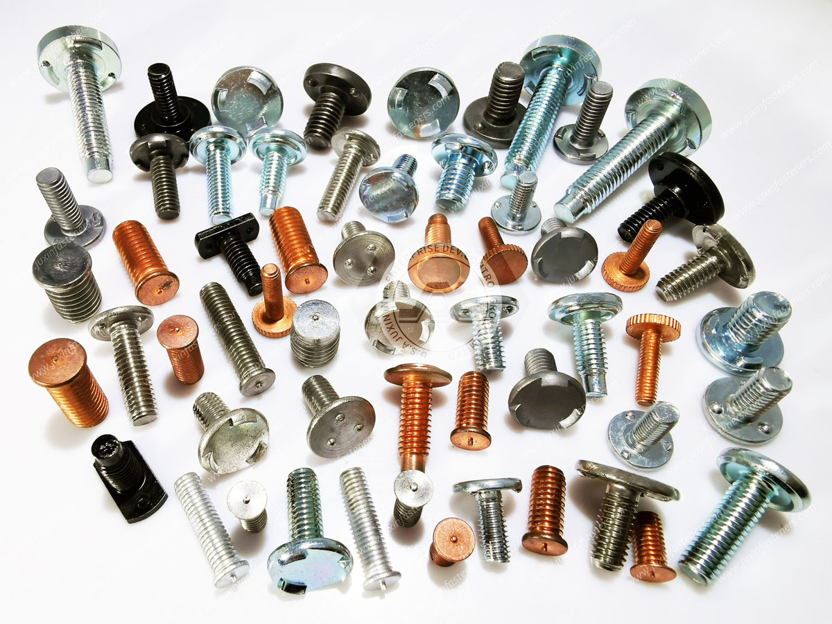
JUXIN FASTENERS supports selected OEM and drawing-based requirements for threaded weld studs, CD weld studs, drawn-arc weld studs,
grounding studs, weld nuts and custom weld fasteners for railway, electrical equipment and industrial manufacturing applications.
For primary structural, bogie, running-gear, braking, crash-related or other safety-critical railway applications,
weld-fastener selection and welding procedures must follow the applicable OEM-controlled drawing, project specification, welding procedure and formal validation requirements.
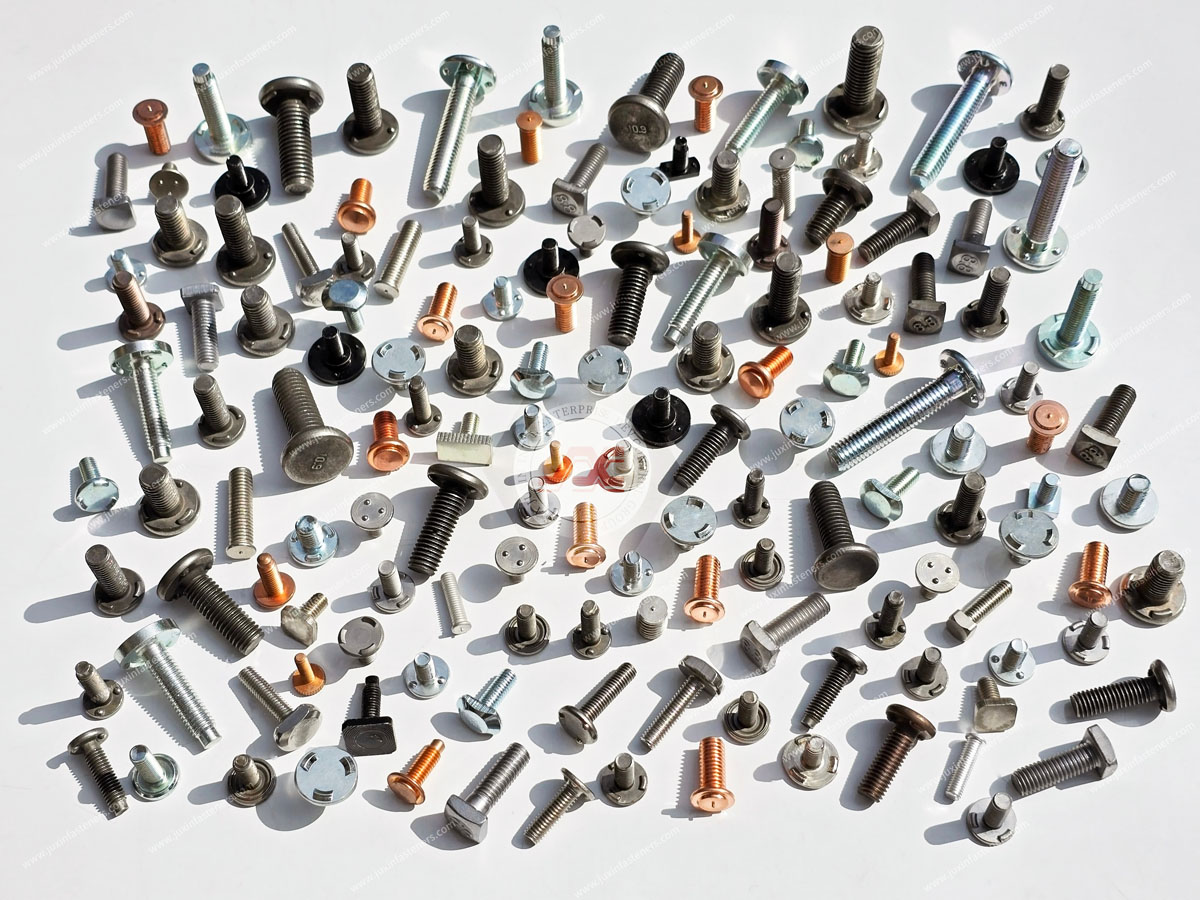
A weld stud is a fastening component designed to be welded directly to a metallic parent material.
Depending on the application, the stud can provide:
A threaded mounting point
An equipment attachment point
A cable-support attachment
An electrical bonding or grounding point
A locating or mounting feature
Unlike a conventional bolt-and-nut assembly, stud welding can eliminate the need for a through-hole and backside hardware in suitable applications.
But:
Weld Stud ≠ Universal Replacement for Bolt and Nut.
The correct joining method depends on load, serviceability, parent material, access and application criticality.
Potential applications include selected:
Electrical cabinets
Electronic equipment enclosures
HVAC assemblies
Cable trays
Harness supports
Junction boxes
Equipment brackets
Interior panels
Partition structures
Lighting equipment
Equipment covers
Battery-related equipment
Grounding and bonding connections
Communication equipment
Underfloor equipment enclosures
Not every location requires the same stud or welding process.
| Railway Application | Typical Function | Key Engineering Consideration |
|---|---|---|
| Electrical cabinet | Equipment mounting | Sheet thickness / distortion |
| Grounding point | Cable-lug attachment | Mechanical + electrical interface |
| HVAC assembly | Bracket attachment | Vibration / service load |
| Cable tray | Support attachment | Load direction / fatigue |
| Interior module | Mounting point | Weight / accessibility |
| Equipment enclosure | Threaded attachment | Thin-sheet welding |
| Battery equipment | Bracket / enclosure attachment | Load / electrical separation |
| Underfloor equipment | Mounting support | Corrosion / vibration / environment |
This matrix is a design starting point, not a universal railway specification.
In suitable applications, weld studs can offer:
One-sided installation access
No through-hole for the stud itself
Reduced loose hardware
Fast production
Defined attachment locations
Compatibility with mechanized installation
Clean opposite-side appearance in selected processes
But these advantages should not be overstated.
The parent material must still support:
Welding
Local thermal input
Service load
Stud load transfer
Environmental exposure
The stud may be permanently welded to the structure while the mating nut, bracket or electrical connection remains serviceable.
The complete assembly can still require inspection and maintenance.
A welded stud may eliminate rotation at the stud-to-parent-material interface, but the mating threaded joint can still experience:
Preload loss
Nut loosening
Fatigue
bracket movement
Therefore:
Welded Stud ≠ Anti-Loosening System.
A typical threaded weld-stud assembly can contain three different functional interfaces:
1. Stud-to-Parent-Material Weld
2. Stud Thread-to-Nut Connection
3. Mounted Component-to-Parent-Structure Interface
Each can fail differently.
For example:
Weld can fail while thread remains intact
Nut can loosen while weld remains intact
Bracket can deform while stud remains intact
This is why:
Stud Strength ≠ Weld Strength ≠ Complete Joint Strength.
Different stud-welding processes are suited to different materials, geometries and production requirements.
Two important technologies are:
Capacitor Discharge (CD) Stud Welding
Drawn-Arc Stud Welding
The welding process should be selected before treating the stud as a commodity component.
Capacitor discharge stud welding uses stored electrical energy discharged over a short welding cycle.
CD weld studs are often considered for relatively thin metallic components where low heat input and backside appearance are important.
Potential railway applications can include selected:
Electrical enclosures
Equipment housings
Thin-sheet brackets
Interior equipment
Cable-management assemblies
depending on parent material and design.
CD welding uses relatively concentrated and short-duration heat input, but it is still a welding process.
Therefore:
Low Heat Input ≠ No Thermal Effect.
Parent-material thickness, surface condition and welding parameters still matter.
Stud diameter, parent material, sheet thickness and process parameters must be compatible.
An oversized stud on an unsuitable thin sheet can cause:
Distortion
backside marking
burn-through
poor weld formation
Drawn-arc stud welding uses an arc between the stud and parent material to form a weld pool before the stud is plunged into the molten material.
It can be used for applications requiring different stud sizes, parent-material thicknesses and mechanical requirements.
Potential railway uses can include selected:
Equipment structures
Structural supports
Heavy brackets
Underfloor equipment
subject to application-specific engineering and welding qualification.
Using a higher-capacity welding process does not automatically qualify the joint for a structural railway application.
The application still requires the appropriate:
Joint design
Welding procedure
Process control
Inspection
Validation
Depending on equipment and design, short-cycle stud-welding processes may provide another option between conventional CD and longer-cycle drawn-arc approaches.
The process should be selected according to:
Stud geometry
Parent material
thickness
production rate
required weld performance
appearance requirements
rather than marketing terminology.
Some weld fasteners use projection or resistance-welding principles.
These should not automatically be grouped with arc stud welding or capacitor-discharge stud welding.
The process physics, tooling and weld formation can differ.
Therefore:
CD Stud Welding ≠ Drawn-Arc Stud Welding ≠ Projection / Resistance Welding.
This distinction should be defined on the drawing or manufacturing specification.
A common sourcing mistake is asking:
What is the strongest railway weld stud?
The better question is:
What stud and welding process are compatible with the parent structure and required joint function?
The parent material influences:
Weldability
Heat input
Weld formation
distortion
metallurgical behavior
corrosion
Therefore:
Strongest Stud Material ≠ Best Weld Stud Solution.
Carbon steel weld studs can provide useful mechanical performance and weldability in suitable steel assemblies.
Depending on the application, they may also require a surface treatment for corrosion protection.
But:
Carbon Steel Stud ≠ Universal Railway Structural Stud.
Mechanical properties, welding behavior and application requirements must be defined.
Stainless steel weld studs can be useful in selected environments requiring corrosion resistance.
Potential advantages can include resistance to atmospheric corrosion in suitable environments.
However:
Stainless Steel ≠ Corrosion-Proof.
And:
Stainless Steel Weld Stud ≠ Automatically Compatible With Every Parent Material.
Material compatibility, welding procedure and environment must be reviewed.
A4/316-type stainless may provide improved corrosion resistance in some chloride-containing environments.
But the correct choice depends on:
Parent material
Welding process
mechanical requirement
corrosion environment
cost
Therefore:
Higher Corrosion Resistance ≠ Automatically Better Weldability or Joint Performance.
Surface treatment creates an important engineering issue because the stud must both:
Be welded successfully
Meet the final corrosion requirement
Coatings can affect welding behavior depending on the process.
Therefore:
Coating Selection Cannot Be Separated From Welding Process Selection.
A surface-treatment specification may need to define:
Coating system
thickness
passivation / topcoat
friction where threaded assembly is involved
corrosion requirement
masking or weld-zone requirements
where applicable.
Laboratory corrosion testing can support comparison and qualification.
It does not directly predict years of field service.
The complete assembly can contain:
Stud
weld zone
parent material
coating transition
mating nut
bracket
Corrosion can occur at the interface even when the stud itself uses a corrosion-resistant material.
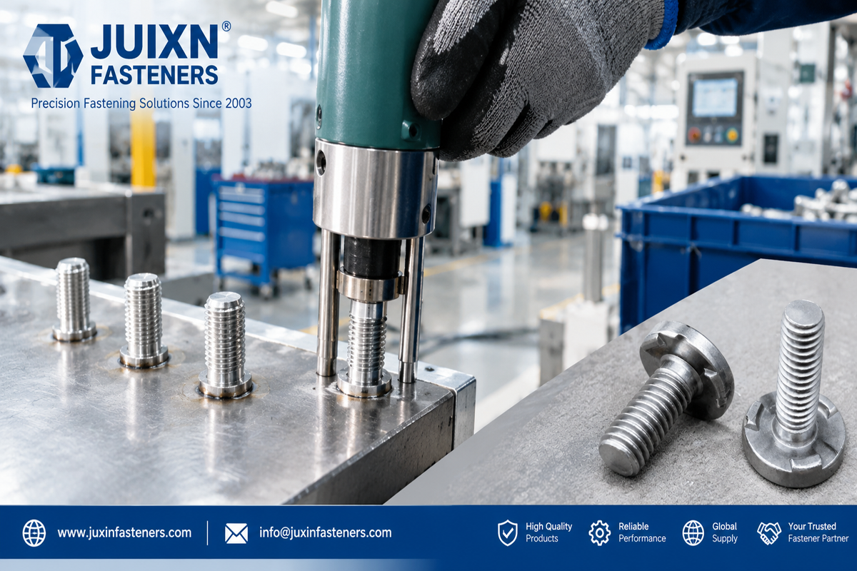
Railway lightweight structures may combine:
Carbon steel
Stainless steel
Aluminum
Copper-containing electrical components
Different combinations can create:
Welding incompatibility
galvanic-corrosion concerns
coating challenges
Therefore:
Material Compatibility ≠ Material Strength Alone.
Aluminum railway structures should not be treated as steel structures with a lighter material.
Aluminum has different:
Thermal conductivity
melting behavior
oxide behavior
mechanical properties
Therefore:
Steel Stud-Welding Parameters ≠ Aluminum Stud-Welding Parameters.
Stud material, equipment and process must be appropriate for the aluminum system.
If the parent aluminum becomes the limiting element, increasing stud strength does not strengthen the complete joint.
A larger-diameter stud may carry more load under some conditions, but joint capacity also depends on:
Weld area
parent-material thickness
parent-material strength
edge distance
bracket geometry
load direction
Therefore:
Larger Stud ≠ Automatically Stronger Railway Joint.
The stud-to-parent-material interface is not merely a manufacturing detail.
Weld geometry affects how load transfers from:
Mounted Component → Nut → Stud → Weld → Parent Structure
This is why weld design belongs in the engineering specification.
Excessive welding energy can create:
Expulsion
Excessive melting
distortion
burn-through
poor geometry
metallurgical problems
Insufficient energy can create:
Incomplete fusion
weak attachment
inconsistent weld formation
The objective is a validated process window.
Depending on the process, important variables can include:
Current
Time
Voltage / stored energy
Lift
plunge
spring pressure
stud geometry
parent-material condition
Therefore:
Single Welding Parameter ≠ Complete Welding Procedure.
The parent surface can contain:
Oil
Oxides
Paint
Scale
Plating
contamination
These can influence weld formation.
Therefore:
Good Stud + Contaminated Surface = Uncontrolled Weld Risk.
Surface preparation should follow the validated process.
Threaded weld studs must remain functional after installation.
Potential issues include:
Weld spatter
heat-related damage
misalignment
handling damage
The welding process and tooling should protect critical threaded features.
A stud can be strongly welded but unusable because the mating thread is damaged.
Both characteristics matter.
Misalignment can create assembly problems even when the weld itself is mechanically acceptable.
Possible consequences include:
Difficult nut installation
bracket misalignment
uneven bearing
assembly interference
Therefore:
Strong Weld ≠ Correct Stud Alignment.
Grounding studs deserve separate engineering treatment because the connection performs both mechanical and electrical functions.
A typical grounding assembly can include:
Parent Structure → Welded Stud → Contact Interface → Cable Lug → Washer → Nut
The stud alone does not determine electrical performance.
Electrical performance can depend on:
Contact surface
coating
cable lug
clamp force
corrosion
vibration
installation
Therefore:
Mechanical Weld Strength ≠ Electrical Bonding Performance.
The old assumption that copper-plated steel automatically creates a high-performance grounding connection is too simplistic.
Electrical performance depends on the entire contact path.
Therefore:
Conductive Coating ≠ Qualified Electrical Connection.
Electrical resistance at an interface can be influenced by:
Oxides
coatings
contamination
contact pressure
corrosion
The complete connection should be evaluated.
A mechanically secure grounding stud does not establish system-level electrical safety.
Protective grounding, equipotential bonding, EMC bonding and other electrical functions must follow the applicable electrical design and project requirements.
Do not assume that an ordinary equipment grounding stud is suitable for:
Traction return current
High fault current
Lightning current
Other high-energy electrical paths
unless specifically engineered and validated for that function.
Electrical-current capability depends on the complete current path and thermal/mechanical effects.
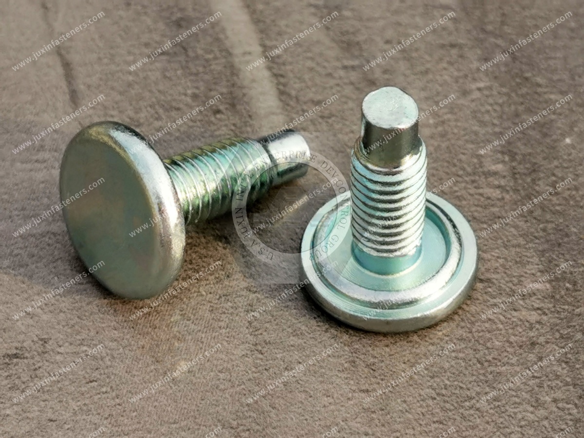
Electrical cabinets can use weld studs for:
Component brackets
Cable supports
Equipment mounting
Grounding points
depending on the design.
Thin cabinet sheet can make distortion control especially important.
Therefore:
Successful Weld ≠ Acceptable Cabinet Appearance.
Mechanical performance, dimensional stability and cosmetic requirements may all matter.
Railway HVAC assemblies may use studs for:
Brackets
Duct supports
Equipment housings
Filter assemblies
Service components
Selection should consider:
Equipment mass
vibration
temperature
corrosion
service access
A weld stud is one part of the mounting system.
Weld studs can provide attachment points for:
Cable trays
Cable clamps
Harness brackets
Sensor supports
Junction boxes
But:
Cable-Support Stud ≠ Electrical Grounding Stud.
The functional requirements are different unless the design explicitly combines both functions.
Selected interior applications may include:
Partition supports
Ceiling equipment
Lighting supports
Equipment covers
Interior brackets
depending on structure and project requirements.
Interior-system requirements can include:
Mechanical retention
vibration
appearance
fire-related material requirements
serviceability
The complete interior component—not merely the stud—must satisfy applicable project requirements.
Battery and energy-storage equipment can contain:
Trays
Enclosures
Brackets
Cable supports
Electrical interfaces
Weld studs may provide attachment points in selected components.
But:
Fastener ≠ Battery-System Safety Qualification.
Battery electrical, thermal, crash and fire requirements are system-level engineering responsibilities.
Even if both are welded studs, their functional requirements may be different.
A mounting stud may primarily carry mechanical load.
A grounding stud may form part of an electrical path.
The specification must identify the function.
Railway weld-stud applications should be classified before product selection.
Examples can include selected:
Covers
Cabinets
Cable supports
Interior equipment
Examples can include selected:
Equipment brackets
HVAC supports
Auxiliary structures
Examples may include:
Primary load-bearing structures
Bogie / running-gear components
Braking-related structures
Crash-related structures
For the last category:
Catalog Weld Stud ≠ Safety-Critical Railway Approval.
The OEM or project specification governs.
Dynamic railway loads can create cyclic stress.
Fatigue behavior depends on more than stud tensile strength.
Relevant variables can include:
Weld geometry
stress concentration
parent material
load direction
residual stress
joint design
Therefore:
High Tensile Strength ≠ High Fatigue Strength.
Railway weld studs can experience:
Axial tension
shear
combined loading
bending
A single load rating should not be used to describe every application.
If the surrounding sheet or structure fails first, increasing stud strength does not increase complete joint capacity.
The welded end of the stud may remain fixed while the mating nut can still lose preload or rotate.
Therefore:
Permanent Weld ≠ Permanent Clamp Load.
Where a nut secures the mounted component, the threaded-joint design still needs:
Preload
friction
locking strategy
installation control
All-metal lock nuts, prevailing-torque nuts or other locking methods can be used where specified.
But:
Prevailing Torque ≠ Preload.
The locking feature does not replace correct tightening.
The torque applied to the nut is an installation input.
Resulting preload depends on:
Thread friction
Bearing friction
coating
lubrication
Therefore:
Same Torque + Different Friction ≠ Same Clamp Load.
Even when the coating is applied away from the weld interface, it can influence the mating nut's tightening behavior.
Therefore:
Same Stud Geometry + Different Coating ≠ Same Assembly Behavior.
Stud welding can integrate effectively with high-volume manufacturing.
Possible production architectures include:
Manual stud welding
Semi-automatic systems
Automatic stud feeding
Robotic positioning
depending on volume and component geometry.
Automated equipment can improve:
Repeatability
throughput
process-data collection
but:
Automation ≠ Validated Welding Process.
The process still requires:
Correct parameters
equipment maintenance
electrode / gun condition
part positioning
monitoring
inspection
A welding system can record process parameters without directly measuring every aspect of finished weld performance.
Therefore process data should support—not replace—appropriate validation.
Recorded data can help trace:
Time
station
program
welding parameters
But:
Traceability ≠ Proof of Joint Performance.
International and regional standards can provide useful frameworks depending on process and application.
Examples can include requirements within applicable ISO, EN and AWS stud-welding standards and project specifications.
The exact standard should be selected according to:
Welding process
Parent material
component type
railway project
rather than applying one generic standard to every weld stud.
ISO 13918 addresses studs and related components for arc stud welding within its scope.
Where applicable, it can help define stud types and requirements.
But:
ISO 13918 Stud Compliance ≠ Railway Joint Qualification.
The installed weld and railway application remain separate engineering issues.
ISO 14555 addresses arc stud welding of metallic materials within its scope.
It can provide a useful framework for process requirements where applicable.
But:
ISO 14555 Welding Procedure ≠ Automatic Railway Application Approval.
OEM and project requirements still govern the final application.
Certain projects, particularly those using American specifications, may reference applicable AWS requirements for stud welding.
The required standard should be identified from the project documentation.
EN 15085 addresses welding of railway vehicles and components within its scope.
It should not be presented as a universal product certification for every individual weld stud.
Therefore:
EN 15085 ≠ Generic Weld Stud Product Certification.
The relevance depends on the railway component, welding activity and project requirements.
EN 61373 may apply to shock and vibration testing of railway equipment within its scope.
But:
EN 61373 ≠ Weld Stud Product Certification.
The equipment and installed assembly are what matter.
A compliant stud can still produce an unacceptable welded joint if:
Parent material is wrong
Surface preparation is poor
Welding parameters are incorrect
Alignment is poor
A useful engineering framework is:
Failure Mode → Requirement → Test → Acceptance Criteria
Potential failure modes include:
Weld separation
Stud fracture
Parent-material tear-out
Thread stripping
Nut loosening
Fatigue cracking
Corrosion
Electrical resistance increase for grounding applications
Depending on application and welding process, validation may include:
Dimensional inspection
Material verification
Thread inspection
Surface-treatment inspection
Visual weld inspection
Bend testing
Torque testing
Tensile / pull testing
Macro examination
Production weld checks
Corrosion testing
Fatigue testing
Vibration testing
Electrical contact-resistance testing
as applicable.
Tests should correspond to the actual failure mode and application requirement.
A cabinet cable-support stud does not require the same validation plan as a highly loaded structural attachment.
A bend test can provide useful information about stud attachment.
It does not automatically establish:
Fatigue performance
corrosion resistance
electrical performance
complete railway application suitability
Likewise, an axial pull test addresses only one loading condition.
A weld can look acceptable while containing unacceptable internal conditions.
The inspection plan should follow the process risk and project specification.
The stud can perfectly match its drawing and still fail because of:
Welding parameters
parent material
surface condition
equipment
operator / automation process
Therefore:
Fastener Quality + Welding Quality = Installed Joint Quality.
Neither can replace the other.
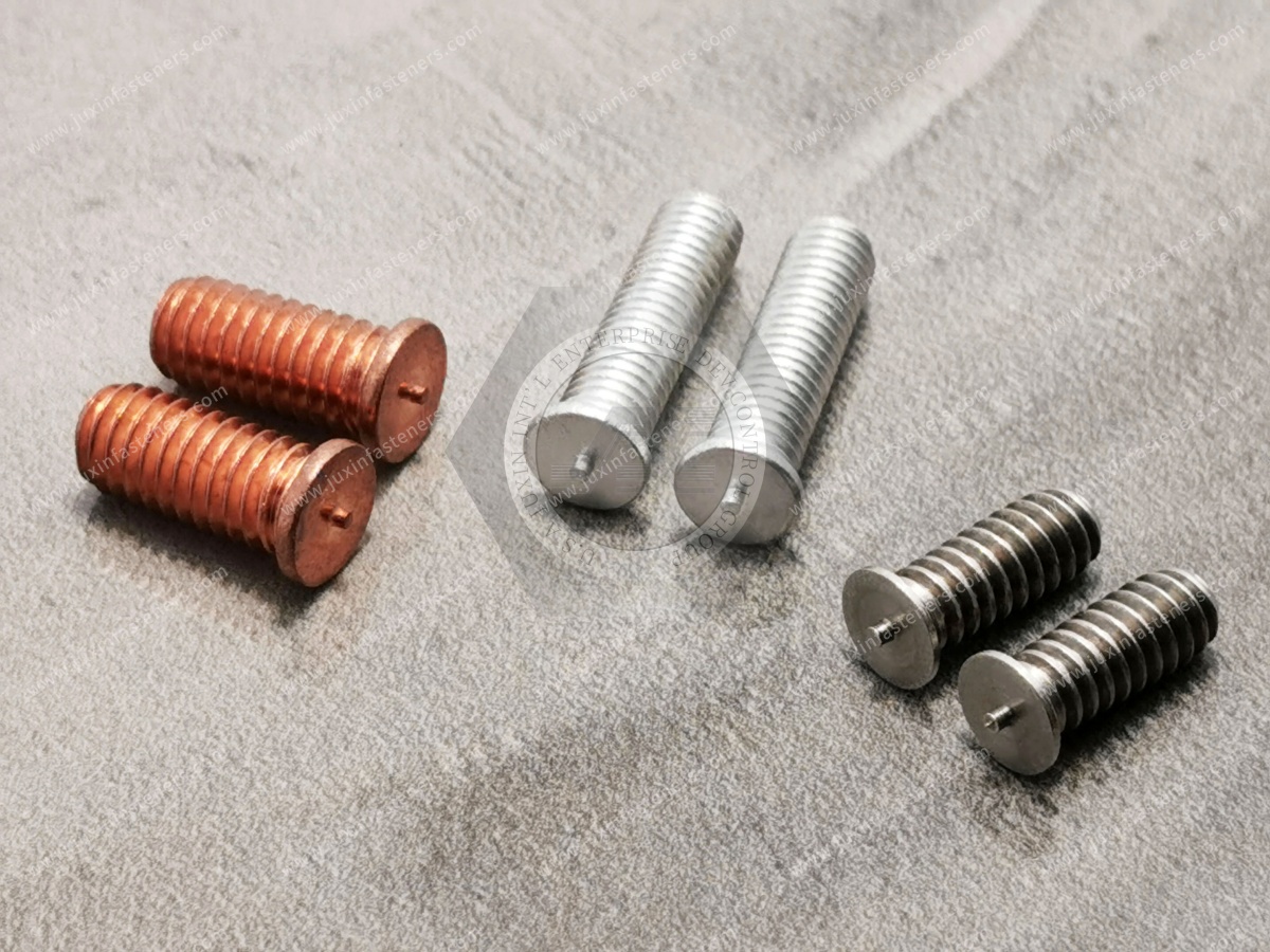
Procurement sometimes treats the stud as a purchased commodity and welding as a separate factory operation.
For critical engineering decisions, they must be linked.
The RFQ should identify:
Stud
Parent material
Welding process
Required performance
so the supplier and application engineer can evaluate compatibility.
Rail OEMs, Tier suppliers and equipment manufacturers should evaluate more than stud price and dimensions.
A practical framework is:
Controlled Drawing + Revision + Stud Material + Mechanical Properties + Thread + Weld-End Geometry + Surface Treatment + Parent Material
+ Welding Process + Installation Parameters + Functional Testing + Inspection + Documentation + Change Control
Two weld studs can have the same:
Thread
length
diameter
while differing in:
Material
mechanical properties
weld-end geometry
manufacturing process
coating
welding behavior
Therefore dimensional interchangeability is not functional equivalence.
For stud welding, the end geometry can influence weld formation.
Therefore:
Same Thread + Same Length ≠ Same Weld Performance.
This is particularly important during second-source development.
When qualifying an alternate supplier, compare:
Drawing and revision
Material
Mechanical properties
Thread
Stud geometry
Weld-end geometry
Surface treatment
Welding-process compatibility
Weld parameters
Functional test results
Production validation
Even when dimensions appear equivalent, a change in:
Material
weld-end geometry
coating
manufacturing process
can influence welding behavior.
Therefore:
Second Source ≠ Drop-In Welding Equivalence.
A material certificate can confirm important raw-material information.
It does not validate the installed weld.
The fastener and installation process are separate controlled elements.
Depending on stud geometry and volume, manufacturing can involve:
Cold heading
Thread rolling
Machining
Secondary forming
Surface treatment
Custom weld studs may combine forming and machining.
Cold heading can be efficient for higher-volume stud production.
CNC machining can be useful for:
Complex geometry
Prototype development
Lower-volume special components
But:
CNC ≠ Automatically Better Weld Stud.
And:
Cold Heading ≠ Automatically Better Weld Stud.
The correct process depends on geometry, material, volume and functional requirements.
Thread rolling can provide efficient thread production for suitable stud designs.
But:
Rolled Thread ≠ Automatic Fatigue Qualification.
The complete component and welded joint still require appropriate validation.
Critical tolerances should be linked to function.
Unnecessary precision can increase:
Tooling cost
inspection cost
scrap
without improving the welded joint.
Early DFM review should consider:
Stud diameter
length
thread
weld-end geometry
cold-heading feasibility
machining requirements
material
coating
welding process
automated feeding
inspection
before production tooling is finalized.
Railway mechanical, welding, electrical and manufacturing engineers searching for railway weld studs may be asking:
Which weld stud should I use for railway equipment?
What is the difference between CD and drawn-arc stud welding?
Can weld studs be used on thin sheet?
How should a grounding stud be welded?
What material should a railway weld stud use?
How does coating affect stud welding?
What causes a weld stud to fail?
How should weld studs be tested?
Can weld studs be used on aluminum railway structures?
How do I qualify a second-source weld stud?
These questions require application-specific answers.
Commercial searches can include:
Railway weld stud manufacturer
Railway weld stud supplier
Threaded weld stud manufacturer
CD weld stud supplier
Drawn arc weld stud manufacturer
Grounding stud supplier
Railway grounding stud manufacturer
Custom weld stud manufacturer
Rail equipment fastener supplier
OEM weld stud supplier
Second-source weld stud manufacturer
Procurement should convert these searches into controlled technical RFQs rather than buying by thread size alone.
Provide:
Railway vehicle / equipment
Installation location
Joint function
Application criticality
Specify:
Thread
diameter
length
head / flange geometry if applicable
weld-end geometry
drawing revision
Provide:
Stud material
mechanical-property requirement
Parent material
Parent-material grade
Parent-material thickness
Define:
CD
Drawn arc
Short cycle
Resistance / projection process
Other approved process
Provide:
Tensile load
Shear load
Combined load where applicable
Fatigue requirement where applicable
Define:
Mating nut
Tightening requirement
Preload where specified
locking method
friction requirement
Specify:
Coating
thickness
topcoat
corrosion requirement
For grounding or bonding applications, define:
Electrical function
Cable lug / conductor
Contact interface
Contact-resistance requirement
Current requirement where applicable
Fault-current requirement where applicable
Specify:
Temperature
Humidity
Condensation
Chlorides
vibration
shock
Define:
Weld inspection
Bend / torque / pull test
macro examination
fatigue
corrosion
vibration
electrical testing
as applicable.
Provide:
Prototype quantity
Annual volume
Packaging
Documentation
Traceability
PPAP or customer-specific submission requirements where applicable
Change-control requirements
Procurement should evaluate:
Total Installed Cost = Stud Price + Welding Equipment + Installation + Tooling + Cycle Time + Inspection + Rework + Scrap + Downtime + Maintenance + Logistics + Supply Risk
A lower-cost weld stud can become an expensive solution if it causes:
Feeding problems
inconsistent welding
excessive rework
distortion
production downtime
For high-volume railway equipment manufacturing, process stability can have more commercial impact than a small difference in piece price.
Standard weld studs can reduce:
Tooling
Lead time
qualification complexity
when they meet the application.
Custom weld studs may be appropriate where the project requires:
Special geometry
specific weld-end design
unusual thread
integrated location features
restricted installation space
But:
Custom Weld Stud ≠ Automatically Better Weld Stud.
A custom feature should solve a defined engineering or manufacturing problem.
This page should serve as the dedicated Railway Weld Studs / Stud Welding / Equipment Mounting engineering resource.
Recommended internal links include:
Railway Fasteners → rolling-stock fastening application hub
Railway Electrical Equipment Fasteners → cabinets and power equipment
Railway Grounding Studs → grounding-stud product and application guide
Railway Electrical Bonding Fasteners → grounding-connection engineering
Railway Signal Equipment Fasteners → trackside signaling and enclosures
Railway Fastener Engineering → vibration, preload and joint design
Railway Anti-Loosening Fasteners → locking technology selection
Railway Bolt Loosening → preload-loss and failure analysis
Railway Fastener Installation → torque and preload control
Railway Threaded Inserts → aluminum and lightweight structures
Fastener Surface Treatment & Coating Selection → coating and corrosion
Zinc-Nickel Coated Fasteners → Zn-Ni coating engineering
Stainless Steel Fasteners → corrosion-resistant fastener selection
Custom Fastener Manufacturing → drawing-based OEM development and DFM
Use the existing indexed JUXIN FASTENERS URL when implementing these internal links.
They can provide welded attachment points for electrical cabinets, HVAC equipment, cable systems, interior equipment, brackets and grounding connections, depending on the railway design.
CD stud welding uses stored electrical energy over a short cycle and is often considered for relatively thin materials.
Drawn-arc stud welding forms an arc and weld pool and can support different stud and parent-material configurations. Process selection must follow the application.
Not as a general rule. Bolted and welded-stud joints transfer load differently, and complete joint capacity depends on the fastener, weld, parent material and geometry.
No. The welded stud may remain attached while the mating nut or mounted component experiences preload loss or movement.
No. Parent-material thickness, weld geometry, load direction and joint design can become limiting factors.
Yes, selected stud-welding processes can be appropriate for thin sheet, but stud size, sheet thickness, material and welding parameters must be compatible.
No. It uses a short-duration welding cycle with relatively concentrated heat input, but thermal effects still exist.
Yes, suitable aluminum stud-welding systems can be used in appropriate designs, but steel welding parameters and material assumptions should not be transferred directly to aluminum.
No. Material selection depends on parent material, welding compatibility, mechanical requirements, corrosion environment and cost.
No. A4/316-type stainless may improve corrosion resistance in certain environments, but it is not automatically the best overall engineering solution.
No. Electrical performance depends on the complete grounding connection, including the contact surface, conductor, clamp load, coating and environment.
No. Mechanical weld performance and electrical bonding performance are separate requirements.
No. ISO 13918 addresses welding studs within its scope. Railway application qualification remains separate.
No. It provides requirements for arc stud welding within its scope; OEM and railway-project requirements still govern the application.
No. EN 15085 concerns welding of railway vehicles and components within its scope and should not be represented as generic individual weld-stud certification.
JUXIN FASTENERS can support selected drawing-based threaded weld studs, CD weld studs, grounding studs and custom weld fasteners according to geometry,
material, surface treatment, welding process, functional requirements and production volume.
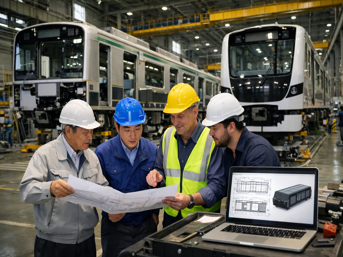
The weak sourcing approach is:
Need Attachment Point → Choose Strong Stud → Weld It → Assume Reliable Joint
The stronger engineering approach is:
Railway Application → Criticality → Parent Material → Thickness → Load Path → Stud Geometry → Welding Process → Welding Parameters
→ Threaded Assembly → Corrosion → Vibration → Inspection → Validation → Supplier Qualification
The key principles are:
Strong Stud ≠ Strong Welded Joint
Weld Stud ≠ Universal Replacement for Bolt and Nut
No Through-Hole ≠ No Joint Engineering
Permanent Attachment ≠ Maintenance-Free Attachment
Weld Stud ≠ Vibration-Proof Connection
Welded Stud ≠ Anti-Loosening System
Stud Strength ≠ Weld Strength ≠ Complete Joint Strength
CD Stud Welding ≠ Zero Heat Input
Low Heat Input ≠ No Thermal Effect
Thin Sheet ≠ Automatically Suitable for Any CD Stud
Drawn-Arc ≠ Automatically Structural Qualification
CD Stud Welding ≠ Drawn-Arc Stud Welding ≠ Projection / Resistance Welding
Strongest Stud Material ≠ Best Weld Stud Solution
Carbon Steel Stud ≠ Universal Railway Structural Stud
Stainless Steel ≠ Corrosion-Proof
Stainless Steel Weld Stud ≠ Automatically Compatible With Every Parent Material
316 Stainless ≠ Automatically Better Than 304
Higher Corrosion Resistance ≠ Automatically Better Weldability or Joint Performance
Coating Selection Cannot Be Separated From Welding Process Selection
Coating Name ≠ Complete Coating Specification
Salt Spray Hours ≠ Railway Service Life
Corrosion-Resistant Stud ≠ Corrosion-Resistant Welded Assembly
Material Compatibility ≠ Material Strength Alone
Steel Stud-Welding Parameters ≠ Aluminum Stud-Welding Parameters
Stronger Steel Stud ≠ Stronger Aluminum Structure
Stud Diameter ≠ Joint Capacity
Larger Stud ≠ Automatically Stronger Railway Joint
More Welding Energy ≠ Better Weld
Single Welding Parameter ≠ Complete Welding Procedure
Good Stud + Contaminated Surface = Uncontrolled Weld Risk
Weld Strength ≠ Thread Quality
Strong Weld ≠ Correct Stud Alignment
Grounding Stud ≠ Qualified Grounding System
Mechanical Weld Strength ≠ Electrical Bonding Performance
Copper-Plated Stud ≠ Automatically Better Grounding Connection
Conductive Coating ≠ Qualified Electrical Connection
Low Bulk Resistance ≠ Low Contact Resistance
Mechanical Fastening ≠ Electrical Safety
Grounding Stud ≠ Traction Return Connection
Stud Size ≠ Fault-Current Rating
Successful Weld ≠ Acceptable Cabinet Appearance
Cable-Support Stud ≠ Electrical Grounding Stud
Fastener ≠ Battery-System Safety Qualification
Battery Mounting Stud ≠ Grounding Stud
Catalog Weld Stud ≠ Safety-Critical Railway Approval
High Tensile Strength ≠ High Fatigue Strength
Tensile Strength ≠ Shear Strength
Stud Strength ≠ Parent-Material Strength
Permanent Weld ≠ Permanent Clamp Load
Lock Nut ≠ Correct Preload
Prevailing Torque ≠ Preload
Torque ≠ Preload
Same Torque + Different Friction ≠ Same Clamp Load
Same Stud Geometry + Different Coating ≠ Same Assembly Behavior
Automation ≠ Automatic Quality
Automation ≠ Validated Welding Process
100% Process Monitoring ≠ 100% Defect Detection
Digital Traceability ≠ Weld Qualification
ISO 13918 Stud Compliance ≠ Railway Joint Qualification
ISO 14555 Welding Procedure ≠ Automatic Railway Application Approval
EN 15085 ≠ Generic Weld Stud Product Certification
EN 61373 ≠ Weld Stud Product Certification
Component Standard ≠ Installed Joint Qualification
More Testing ≠ Better Engineering
Bend Test ≠ Complete Weld Qualification
Pull Test ≠ Complete Joint Qualification
Visual Inspection ≠ Internal Weld Quality
Drawing Compliance ≠ Welded Joint Validation
Fastener Quality + Welding Quality = Installed Joint Quality
Same Dimensions ≠ Functional Equivalence
Same Thread + Same Length ≠ Same Weld Performance
Second Source ≠ Drop-In Welding Equivalence
Material Certificate ≠ Weld Performance
Stud Certification ≠ Welding Process Qualification
CNC ≠ Automatically Better Weld Stud
Cold Heading ≠ Automatically Better Weld Stud
Rolled Thread ≠ Automatic Fatigue Qualification
Tighter Tolerance ≠ Better Weld Stud
Lowest Stud Price ≠ Lowest Welded-Joint Cost
Custom Weld Stud ≠ Automatically Better Weld Stud
For railway design engineers, the objective is to engineer the complete load path from the mounted equipment through the nut, stud, weld and parent structure.
For manufacturing engineers, the objective is to create a controlled welding process capable of producing repeatable joints without unacceptable distortion, thread damage or rework.
For electrical engineers, a grounding stud must be evaluated as part of the complete electrical bonding connection rather than as a conductive fastener alone.
For procurement and supplier-development teams, the objective is to qualify not only the stud drawing and unit price, but also material, weld-end geometry,
surface treatment, welding-process compatibility, installation behavior and functional performance.
JUXIN FASTENERS supports selected railway equipment applications with:
Threaded weld studs
Capacitor discharge weld studs
Drawn-arc weld studs
Grounding studs
Weld nuts
Custom weld fasteners
Carbon steel fasteners
Stainless steel fasteners
Zinc-nickel coated fasteners
Cold-formed components
CNC precision components
OEM / ODM fastener development
Second-source weld-fastener development
For a railway weld stud RFQ, provide:
2D Drawing + 3D Model + Part / Revision + Railway Application + Application Criticality + Joint Function + Parent Material + Parent-Material Grade
+ Parent-Material Thickness + Stud Material + Stud Diameter + Thread + Weld-End Geometry + Welding Process + Load Direction
+ Tensile / Shear / Fatigue Requirement Where Applicable + Surface Treatment + Corrosion Environment + Mating Nut + Tightening Requirement
+ Locking Requirement + Vibration / Shock Requirement + Weld Inspection Requirement + Functional Validation + Prototype Quantity + Annual Volume
For grounding or electrical-bonding studs, additionally provide:
Electrical Function + Cable Lug / Conductor + Contact Interface + Contact-Resistance Requirement + Current / Fault Requirement Where Applicable + Environmental Validation
For safety-critical railway applications, also provide the applicable OEM / railway-project drawing, welding specification, approved welding procedure, inspection plan and validation requirements.
JUXIN FASTENERS
Railway Weld Studs | Threaded Weld Studs | CD Weld Studs | Grounding Studs | Custom Weld Fasteners | OEM Railway Fasteners
Email: info@juxinfasteners.com
Website: www.juxinfasteners.com
Contact Us
Tel.:
+86 020 8621 0320
+86 020 3121 6067
E-mail:
Technical Support:
Navigation
SEND INQUIREY



