
Call Us
+86 136 6007 9809
Call Us
+86 136 6007 9809

Oct. 26, 2023
Specifying a clip nut requires more than identifying a thread size.
A description such as “M6 clip nut” may identify the general thread requirement, but it does not define how the fastener fits the panel, where the thread is positioned,
how the clip is retained, or whether it will align with the mating screw.
For design engineers, manufacturing teams, procurement engineers, and supplier-development professionals, these interface dimensions often determine whether a clip nut works in production.
Depending on the product geometry, related fasteners may be described as clip nuts, U-nuts, spring nuts, threaded clip nuts, or sheet metal clip nuts.
Commercial terminology varies, making dimensional definition even more important for OEM and second-source sourcing.
A useful engineering specification should connect four things:
clip nut geometry + finished panel geometry + mating screw + assembly conditions.
This guide explains the dimensions and specifications that should be reviewed when selecting, drawing, replacing, or sourcing clip nuts.
Consider two clip nuts with the same nominal thread.
Both may accept the same screw, yet one can work correctly while the other fails in the assembly.
Why?
They may have different:
Panel grip geometry
Clip opening
Clip reach
Thread-center position
Overall width
Overall length
Formed height
Material thickness
Spring geometry
Installation envelope
The thread is only one interface within the complete component.
For this reason:
M6 clip nut ≠ complete clip nut specification.
The same principle applies to inch-thread configurations.
For a conventional metric threaded feature, a designation may identify the nominal thread diameter and pitch.
For example, a metric thread can be specified using a format such as:
M6 × 1.0
where the designation identifies the required metric thread geometry.
However, the thread specification should follow the applicable customer drawing or recognized thread standard.
The thread designation does not define:
Panel thickness
Clip reach
Clip width
Thread location
Fastener material
Surface finish
Those requirements must be specified separately.
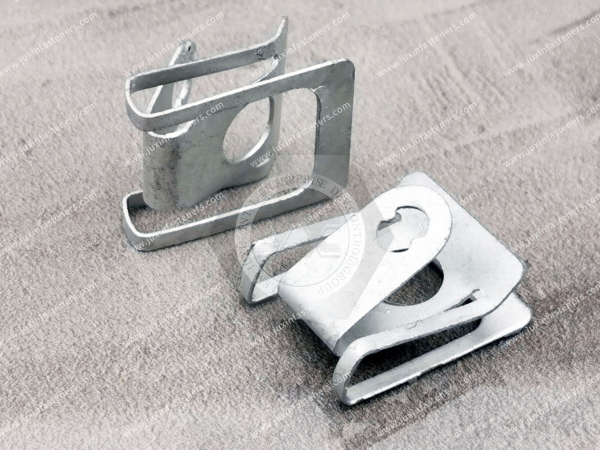
Clip nuts used in North American equipment may also use inch-series threads.
When sourcing an inch-thread clip nut, provide the complete thread designation from the customer drawing rather than converting approximately from a metric size.
Metric and inch threads should not be treated as interchangeable because their diameters and thread geometry can differ.
For second-source projects, the actual mating screw is also valuable for verification.
For an edge-mounted clip nut or U-nut, panel thickness is one of the most important interface dimensions.
The fastener must fit the actual production panel.
Engineering evaluation should consider:
Nominal sheet thickness
Sheet thickness tolerance
Paint
Powder coating
Plating
Multiple material layers
Local forming
Edge burrs
The clip does not interact with an abstract nominal sheet value.
It interacts with the finished panel condition.
This distinction becomes particularly important when a clip nut that worked during prototype assembly becomes difficult to install after the production coating process is introduced.
The clip opening determines how the fastener initially interfaces with the panel.
Depending on the design, the clip body elastically deflects during installation.
If the relationship between the opening and finished panel is incorrect, possible symptoms include:
Excessive installation force
Insufficient pre-assembly retention
Clip deformation
Panel damage
Coating damage
Incorrect seating
Maximum retention force should not automatically be the design objective.
The fastener needs a controlled grip condition appropriate for the production and service requirements.
Clip reach is a critical but sometimes overlooked specification.
For an edge-mounted U-nut or clip nut, reach describes the relationship between the panel edge and the location of the screw-engagement or threaded feature.
If the reach does not correspond with the mating-panel geometry, the screw and thread may not align.
Possible consequences include:
Difficult screw starting
Angled screw entry
Cross-threading
Assembly delays
Rework
Thread damage
Two clip nuts with the same thread size and similar appearance can therefore be functionally different because their reach differs.
The panel drawing is just as important as the clip-nut drawing.
For an edge-mounted fastener, the panel's edge-to-hole-center distance should correspond with the clip's thread-center location.
The relationship can be expressed conceptually as:
panel edge → clip seating position → thread center → panel hole → screw axis
Each feature contributes to alignment.
This makes edge-to-hole-center distance particularly important in second-source qualification.
The thread center must be correctly located relative to the clip body.
Relevant dimensions can include:
Longitudinal position
Lateral position
Height relative to the panel
Relationship to locating features
Relationship to the panel hole
A small positional change can matter when the surrounding assembly has limited clearance.
For high-volume screw installation, positional repeatability can also influence assembly consistency.
Overall length can affect:
Installation clearance
Packaging space
Interference with nearby components
Clip retention geometry
Compatibility with existing brackets
An alternative clip nut should therefore be checked against the available assembly envelope rather than qualified only by thread and reach.
Width can become critical in compact assemblies.
Potential interference can occur with:
Panel bends
Ribs
Adjacent holes
Welded features
Electrical components
Brackets
Other fasteners
For an existing product, compare the proposed replacement against the actual available space.
The height of the clip assembly can affect the final stack-up and screw path.
Depending on the design, excessive height may:
Reduce available clearance
Change mating-component position
Affect screw engagement
Interfere with nearby components
Height should therefore be considered part of the three-dimensional assembly interface.
The thickness of the material used to manufacture the clip body can influence:
Forming behavior
Spring response
Installation behavior
Component stiffness
Available packaging space
Material thickness should not be changed during second-source development without considering its relationship to material properties and formed geometry.
A thicker component made from a different material is not automatically functionally equivalent to the original.
The mating screw needs a clear path into the threaded or engagement feature.
The assembly should account for:
Panel-hole diameter
Mating-component hole
Screw head access
Screw-entry angle
Clip position
Thread location
If the screw contacts the panel or clip before entering the thread correctly, cross-threading or assembly difficulty may result.
“Grip range” and “panel thickness” are related concepts, but they should not be used carelessly.
A supplier may describe a fastener as suitable for a certain panel range, but the actual assembly can also be affected by:
Coating
Local panel geometry
Installation method
Retention requirement
Clip design
For OEM projects, the customer's actual finished panel should be used for validation where appropriate.
Catalog grip information is a selection starting point, not a substitute for assembly verification.
Coating is often treated only as a corrosion specification.
For clip-on fasteners, it can also become a dimensional variable.
Consider a panel that receives:
Paint
Powder coating
Plating
Another surface treatment
The effective thickness at the clip interface may differ from the raw sheet condition.
Similarly, coating on the fastener itself can affect local fit depending on the geometry.
When the clip-panel interface has limited dimensional margin, coating changes should be included in the tolerance analysis.
A common mistake is evaluating every component independently.
The more important question is whether all components remain compatible when their allowable dimensional variation accumulates.
A simplified alignment chain may include:
panel edge position + panel-hole position + clip seating position + clip reach + thread-center position + mating-component hole position + screw axis
Each individual feature may meet its drawing requirement.
Yet the combination can still create marginal screw alignment.
This is why intermittent assembly problems are often more difficult to diagnose than a consistently incorrect part.
A prototype may assemble perfectly when every component is close to nominal dimensions.
Production introduces variation.
A robust design should consider what happens when relevant dimensions approach their allowed limits.
Questions to ask include:
Can the clip still be installed on the thickest finished panel?
Is retention acceptable on the thinnest panel condition?
Can the screw enter when panel-hole and thread-center positions shift in opposite directions?
Does coating reduce available clearance?
Can the fastener seat completely at dimensional extremes?
This type of tolerance thinking provides more engineering value than evaluating nominal CAD geometry alone.
Not every dimension has equal functional importance.
A Critical-to-Quality (CTQ) characteristic should be linked to the actual application.
Depending on the design, potential CTQ characteristics can include:
Thread specification
Clip reach
Clip opening
Thread-center position
Material thickness
Overall formed height
Material
Finish
But the CTQ list should not be copied universally from one clip nut to another.
The correct question is:
Which characteristic can cause the assembly to fail if it varies outside the required condition?
That creates a more meaningful drawing and supplier-control strategy.
Depending on the design, a drawing-controlled clip nut may define:
Thread specification
Overall length
Overall width
Clip opening
Clip reach
Thread-center position
Formed height
Material thickness
Material
Finish
Critical radii or formed features
Dimensional tolerances
Customer-specific requirements
The drawing should focus on the features required to control fit and function.
Adding unnecessary tight tolerances to nonfunctional dimensions can increase manufacturing complexity without improving assembly performance.
Stamped and formed spring components should be toleranced according to their functional requirements and manufacturing process.
Applying unnecessarily tight tolerances to every bend, radius, and free-state dimension may increase cost without creating better assembly performance.
A better strategy is to identify:
Functional locating dimensions
Panel-interface dimensions
Screw-interface dimensions
Material requirements
Critical formed geometry
Then control these according to the actual assembly need.
Spring-style components can change geometry during installation.
This creates an important drawing question:
Is a dimension being controlled in the free state or in the installed condition?
A free-state clip opening, for example, may intentionally differ from panel thickness because the clip deflects during installation.
Engineers should understand which dimensions describe the manufactured part and which describe its functional installed relationship.
This distinction can prevent unnecessary disputes during inspection and supplier qualification.
For a clip nut containing a conventional internal thread, the mating screw should correspond to the specified thread system.
For sourcing, provide:
Complete thread designation
Mating screw information
Required screw length where relevant to the assembly
Customer-specific thread requirements
If the component instead uses formed features designed for a tapping screw, it should not be specified as though it were a conventional machine-thread nut.
The mating screw then becomes part of the fastener specification.
Material selection is not separate from geometry.
For a formed clip, material properties influence how the component behaves when pushed over the panel.
Changing:
Material grade
Material thickness
Heat-treatment condition where applicable
Formed geometry
can alter the clip behavior even if the overall external dimensions remain similar.
For second-source projects, material and geometry should therefore be evaluated together.
Finish should be defined according to the customer and application requirements.
Relevant considerations can include:
Corrosion environment
Panel material
Screw material
Appearance
Dimensional buildup
Assembly behavior
Do not assume that two finishes with similar appearance provide equivalent performance.
Likewise, do not specify a corrosion test or coating thickness unless it is required by the customer specification or validated application requirement.
Automotive clip nuts may be used in suitable:
Body-panel interfaces
Interior structures
Brackets
Covers
Equipment mounting points
Trim-related assemblies
Dimensional control can be particularly important because automotive production may involve:
Coated panels
Formed sheet metal
Automated or powered screw installation
High assembly volumes
Tight packaging
Multiple tolerance contributors
A small thread-center or reach variation can become a significant production issue when repeated across large assembly volumes.
Electrical cabinets, power distribution equipment, control systems, and industrial enclosures can use clip nuts in suitable panel assemblies.
Important specifications may include:
Panel thickness
Thread
Edge-to-hole distance
Clip reach
Material
Finish
Service access
Electrical requirements such as grounding or bonding should be addressed separately by the complete equipment design where applicable.
Data center and AI/HPC equipment contains many sheet-metal structures across:
Equipment enclosures
Power equipment
Cooling equipment
Control systems
Serviceable panels
Brackets
Clip nuts may be appropriate for some interfaces, while cage nuts, rivet nuts, self-clinching fasteners, or other technologies may be better for others.
The panel architecture should determine the fastening method.
HVAC and thermal-management equipment may contain clip nuts in:
Housings
Access panels
Fan enclosures
Brackets
Control compartments
Service covers
Material and finish selection should account for the actual environmental exposure, which can include moisture, condensation, or outdoor service depending on the equipment.
Industrial machinery may use clip nuts for suitable:
Covers
Guards
Housings
Control cabinets
Brackets
Service panels
For machinery applications, distinguish between enclosure or service-panel fastening and primary structural joints.
A convenient clip-style fastener should not automatically be used for a load-bearing connection without appropriate engineering evaluation.
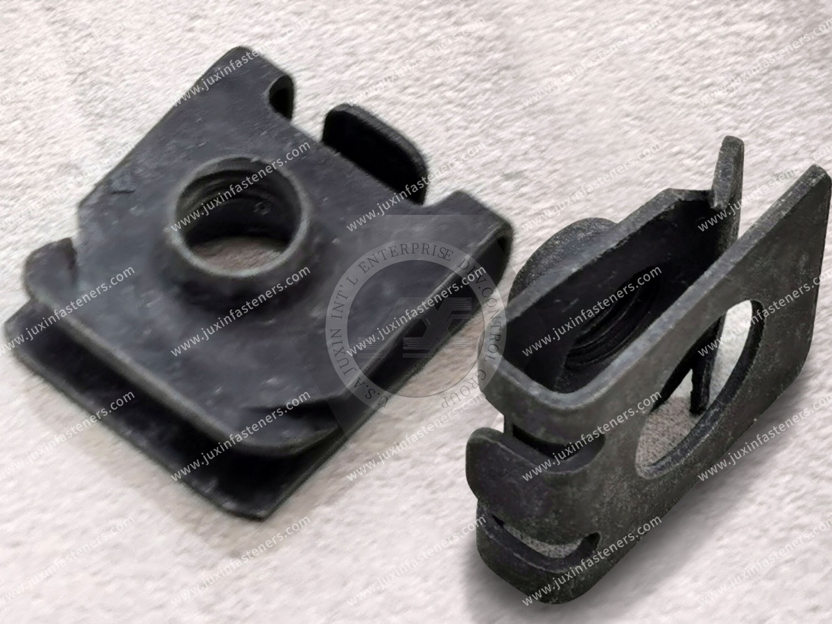
A photograph is useful for identifying the product family.
It is not enough to establish dimensional equivalence.
Two parts can look nearly identical while differing in:
Reach
Clip opening
Thread-center position
Material thickness
Formed height
Thread specification
For a second-source project, provide the drawing and sample whenever available.
A physical sample captures actual geometry, but it has limitations.
A used sample may have:
Permanent spring deformation
Worn threads
Damaged coating
Installation marks
Corrosion
It may no longer represent the original production condition.
The strongest second-source reference package is therefore typically:
controlled drawing + unused approved sample + mating screw + panel/interface information.
When comparing an alternative clip nut with an approved part, do not simply create a table of every measurable dimension.
First identify the functional interfaces.
Compare:
Clip opening
Grip condition
Seating geometry
Compare:
Reach
Thread-center position
Overall envelope
Compare:
Thread
Screw entry
Engagement geometry
Compare:
Material
Material thickness
Finish
This creates a more meaningful equivalence review.
The answer depends on the customer's drawing and qualification requirements.
If the component is controlled by an existing drawing, the proposed part should meet the applicable drawing requirements.
If supplier-specific geometry differs outside the controlled features, functional evaluation may still be required according to the customer's approval process.
The objective is not to make unsupported claims of interchangeability.
The objective is to establish whether the proposed component satisfies the required specification and assembly function.
A standard clip nut may not match every OEM assembly.
Custom development can be considered when the application requires a specific:
Panel thickness
Reach
Thread location
Installation envelope
Spring geometry
Material
Finish
Legacy interface
JUXIN FASTENERS supports standard and custom fasteners, spring nuts, U-nuts, clip nuts, custom stamped components, and drawing-controlled industrial parts.
Development can begin from customer drawings, approved samples, mating components, or application requirements.
For an existing production component, provide where available:
Controlled drawing
Unused approved sample
Complete thread specification
Material
Finish
Panel thickness
Panel drawing
Mating screw
Annual or order volume
If the project is a second-source program, identify any customer-specific qualification requirements.
For a new application, provide:
Application
Panel material
Finished panel thickness
Panel-thickness tolerance
Edge-to-hole-center distance
Hole geometry
Required thread
Mating screw
Available installation envelope
Installation direction
Material requirements
Finish requirements
Environmental conditions
Expected production volume
If CAD or 2D drawings are available, they can help define the surrounding interface.
If the sourcing project is driven by a production issue, also provide the symptom.
For example:
Clip falls off
Installation force too high
Clip will not fully seat
Thread does not align
Screw cross-threads
Coating is damaged
Fastener deforms
Providing the failure condition helps distinguish a dimensional problem from a material, screw, panel, or process problem.
Depending on the assembly, related engineering resources include:
Clip-On Nuts Selection Guide
Clip Nut Installation Problems
U-Nut Applications
Spring Nut vs U-Nut
Rectangular Push Nuts
Sheet Metal Fasteners
Custom Stamped Components
Automotive Fasteners
Cage Nuts
Self-Clinching Fasteners
Rivet Nuts
Each topic addresses a different stage of fastener selection, troubleshooting, or sourcing.
For engineering and procurement teams, the most important principle is:
Thread size identifies the screw interface. It does not define the complete clip nut.
A more useful specification is:
thread + finished panel thickness + clip opening/grip condition + reach + thread-center position + material + material thickness + finish + mating screw + assembly requirements.
That specification gives engineers a better basis for tolerance analysis and gives supplier-development and purchasing teams a stronger basis for comparing potential sources.
For existing production parts, JUXIN FASTENERS can review available drawings, approved samples, mating screws, and panel information for standard sourcing, custom development, or second-source projects.
For new designs, provide the panel geometry, required thread, mating screw, material and finish requirements, application conditions, and expected volume.
Email: info@juxinfasteners.com
Website: www.juxinfasteners.com
 MORE NEWS

Sep. 27, 2026

Sep. 27, 2026

Sep. 27, 2026
Contact Us
Tel.:
+86 020 8621 0320
+86 020 3121 6067
E-mail:
Technical Support:
Navigation
SEND INQUIREY