
Call Us
+86 136 6007 9809
Call Us
+86 136 6007 9809

Apr. 21, 2026
Aluminum Flanged CD Weld Studs for Railway Equipment: Lightweight Sheet Metal Fastening, Welding Validation and OEM Sourcing
Railway vehicle manufacturers face continuous pressure to reduce weight, improve production efficiency and maintain reliable equipment performance under demanding operating conditions.
Modern rolling stock incorporates aluminum panels, stainless steel enclosures, electrical cabinets, passenger interior systems, communication equipment and numerous auxiliary mechanical assemblies.
These components often require permanent threaded mounting points that can be installed accurately without introducing unnecessary drilling operations or visible through-fasteners.
Aluminum Flanged CD Weld Studs, also known as aluminum capacitor discharge weld studs or tip-ignition threaded weld studs,
offer a potential solution for selected lightweight metallic assemblies.
The capacitor discharge (CD) stud welding process uses stored electrical energy to create a short-duration welding event between a compatible stud and workpiece.
When properly selected and validated, CD stud welding can support efficient installation on suitable sheet metal components while limiting localized thermal effects.
However, the suitability of a CD weld stud depends on its material, flange geometry, ignition tip, parent metal, mechanical loading and welding procedure.
In railway manufacturing, an additional distinction is essential: an attachment suitable for an interior equipment panel must not automatically
be treated as suitable for a bogie, primary carbody structure or safety-critical load-bearing connection.
JUXIN FASTENERS supplies aluminum flanged CD weld studs and related industrial fastening components for standard and drawing-based OEM applications.
This guide explains how railway design engineers, manufacturing engineers, production managers and international procurement teams can evaluate
aluminum CD weld studs for suitable equipment and lightweight sheet metal assemblies.
What Are Aluminum Flanged CD Weld Studs?
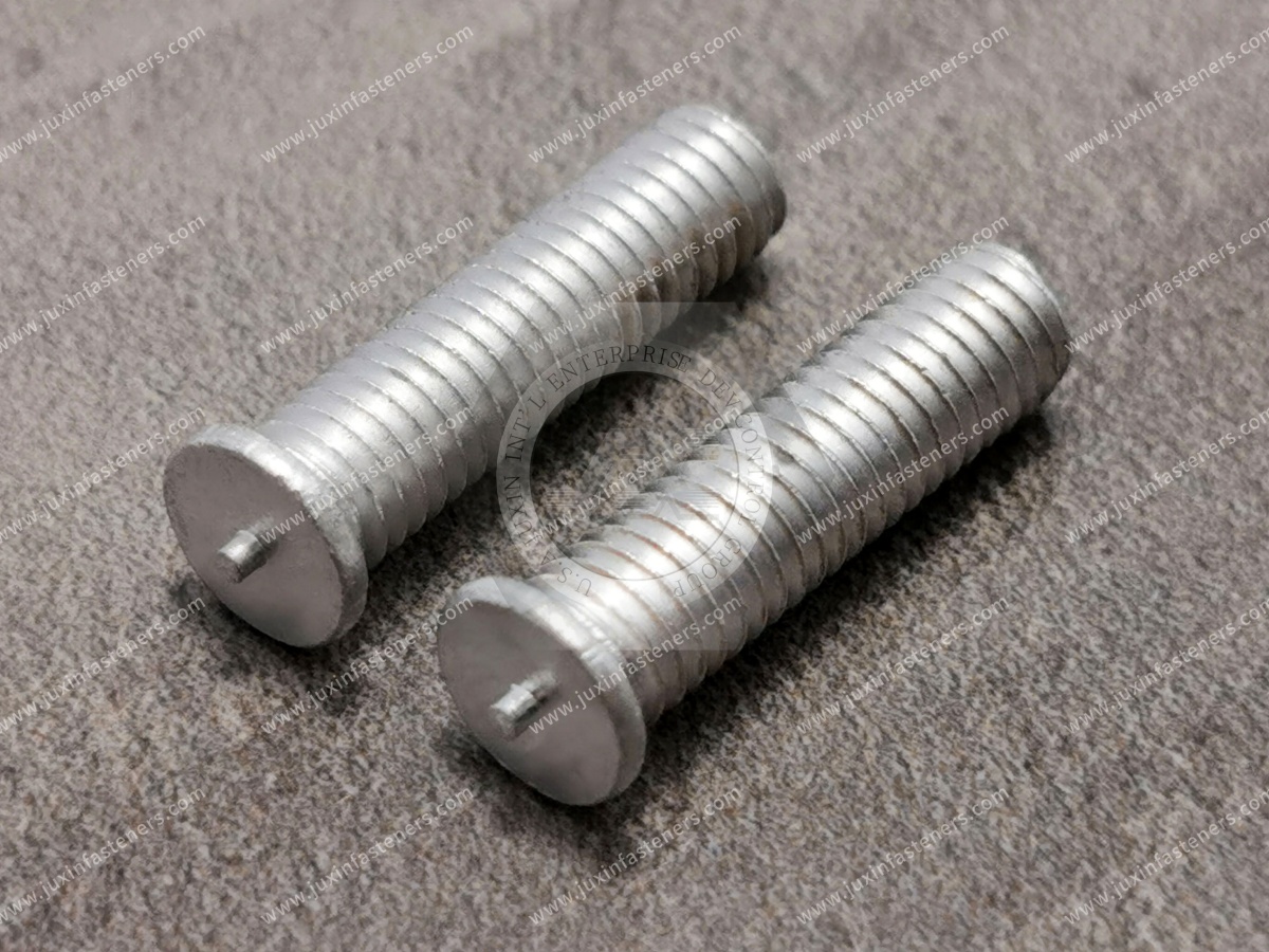
An aluminum flanged CD weld stud is a fastener designed to be attached to a compatible metallic workpiece using capacitor discharge stud welding.
A typical externally threaded configuration consists of an aluminum threaded shank, a flanged weld base and an ignition tip.
The flange provides a defined joining region, while the threaded shank remains accessible for subsequent mechanical assembly.
Depending on the product design, the stud may use metric or Unified inch-series threads.
Main Product Features
External Thread
Provides a permanent male-threaded attachment for compatible nuts, brackets and mechanical accessories.
Flanged Weld Base
Provides a defined welding interface and may increase the effective joining area compared with a similar non-flanged configuration.
Ignition Tip
Supports initiation of the tip-ignition capacitor discharge welding process.
Stud Length
Determines the available thread engagement and clearance for the mating component.
Aluminum Material
May provide weight and corrosion-related advantages in suitable compatible assemblies.
The exact alloy, thread dimensions, flange diameter, flange thickness and ignition-tip geometry must be established by the engineering drawing.
Why Aluminum Fasteners Are Considered for Lightweight Railway Assemblies
Weight reduction is an important engineering objective in many railway vehicle designs.
Aluminum components may be selected where the required mechanical performance can be achieved with a lower material density than conventional steel components.
However, lightweight design does not mean that aluminum is suitable for every fastening location.
Potential Advantages
Reduced fastener mass compared with similar steel geometry
Compatibility with selected aluminum sheet metal assemblies
Corrosion resistance in suitable environments
Nonmagnetic material characteristics
Potential integration into lightweight equipment fabrication
Engineering Limitations
Aluminum alloys have different mechanical and thermal properties from steel.
Thread strength, stiffness, fatigue behavior, corrosion resistance and welding characteristics must be evaluated.
A steel fastener should not automatically be replaced by an aluminum fastener based only on nominal dimensions.
Aluminum Studs Versus Steel and Stainless Steel Studs
The appropriate material depends on the application.
Aluminum may be considered for compatible lightweight aluminum assemblies.
Carbon steel may be appropriate for certain protected industrial components.
Stainless steel may be preferred where corrosion resistance and mechanical requirements justify its use.
The selected stud must also be compatible with the intended welding process and parent material.
Understanding Flange Geometry and Weld Strength
The flange is a functional part of the stud.
A wider weld base may provide a greater effective joining area compared with a similar non-flanged design.
However, the flange does not automatically guarantee higher pull-off strength or vibration resistance.
The actual joint performance depends on weld formation, substrate thickness, material properties and loading.
Flange Diameter
Influences the available welding area and clearance around the attachment.
Flange Thickness
Influences the installed geometry and the position of mating components.
Ignition-Tip Geometry
Influences the initiation and repeatability of the welding event.
Stud Straightness
May affect positioning accuracy and automated feeding.
Thread Engagement
Must be sufficient for the intended mechanical assembly.
Standard Flange Versus Automatic-Feed Flange
Some commercial CD weld stud families distinguish standard flanged studs from reduced-flange automatic-feed configurations.
The two designs may use different tooling and feeding arrangements.
A replacement stud should therefore be evaluated using its complete dimensional specification.
How Tip-Ignition Capacitor Discharge Welding Works
Capacitor discharge stud welding uses electrical energy stored in capacitors to create a short-duration joining event.
The stud is positioned against or near the parent metal according to the selected welding method.
The ignition tip participates in initiating the arc, and the welding equipment controls the discharge and stud movement.
The joining surfaces develop the welded connection during the process.
General Welding Sequence
The workpiece is prepared and positioned.
The stud is loaded into the welding gun or automated installation system.
The welding equipment establishes the required contact or gap condition.
The stored electrical energy is discharged.
The ignition tip initiates the joining event.
The stud movement and joining conditions produce the welded attachment.
The completed joint is inspected according to the applicable acceptance requirements.
Contact CD Welding
Contact operation begins with the stud positioned in the intended contact arrangement.
The welding system initiates the discharge and controls the joining movement.
Gap CD Welding
Gap operation uses a defined initial spacing and movement sequence.
The equipment settings and process behavior differ from contact operation.
The correct method depends on the stud, substrate and welding equipment.
Why CD Welding May Be Useful for Thin Sheet Metal
The short-duration welding event can help limit thermal effects compared with certain longer-duration welding processes.
This may reduce the risk of distortion or reverse-side marking in suitable applications.
However, CD welding does not guarantee that the opposite side of the sheet will remain completely unmarked.
CD Welding Versus Short-Cycle and Drawn-Arc Stud Welding
These processes should not be treated as interchangeable.
CD welding is often considered for suitable thin sheet metal and cosmetic applications.
Short-cycle and drawn-arc stud welding use different equipment arrangements and welding conditions.
The selection should be based on the material, thickness, stud geometry and required mechanical performance.
A welding procedure developed for one process should not automatically be applied to another.
Railway Vehicle Interior Applications
Railway vehicle interiors contain numerous lightweight panels and auxiliary assemblies.
Aluminum flanged CD weld studs may be considered for selected attachments where the mechanical requirements and welding process are compatible.
Interior Panel Supports
Potential applications include suitable lightweight panel brackets and secondary mounting features.
The designer must evaluate panel thickness, vibration exposure and maintenance requirements.
Passenger Information Equipment Housings
Display housings and related equipment may incorporate metallic mounting panels.
CD studs may be considered for suitable internal or auxiliary mounting points.
The complete equipment assembly must meet its applicable performance requirements.
Lighting Equipment Enclosures
Certain lighting equipment housings use lightweight metal panels and brackets.
A CD welded attachment may be appropriate where the joint has been validated for the required mechanical and environmental conditions.
Cable Management Accessories
Cable support brackets and auxiliary hardware may require permanent threaded mounting points.
The design should account for cable loading, vibration, maintenance and electrical safety.
Interior Equipment Covers
Removable covers may use threaded attachments on compatible metallic panels.
The designer should consider repeated assembly, tightening torque and accessibility.
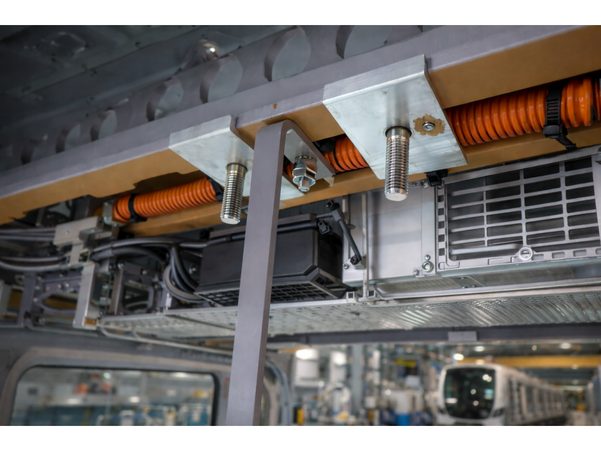
Onboard Electrical Cabinets and Control Enclosures
Modern rolling stock contains electrical distribution equipment, communication systems, monitoring electronics and control assemblies.
These systems often use sheet metal enclosures with internal mounting hardware.
Potential Applications
Auxiliary mounting brackets
Internal equipment support plates
Cable management components
Selected control enclosure accessories
Lightweight instrument housing attachments
The welded stud should not automatically be used as a protective grounding connection or safety-critical electrical attachment.
Electrical bonding and grounding requirements must be evaluated separately.
Railway HVAC and Auxiliary Equipment
Railway heating, ventilation and air-conditioning systems may incorporate metallic covers, control enclosures and secondary sheet metal accessories.
Flanged CD weld studs may be considered for suitable noncritical mounting locations.
However, exterior equipment supports, load-bearing brackets and vibration-sensitive components may require additional structural qualification.
The use of CD studs in these locations should be determined by the responsible railway engineering team.
Why CD Weld Studs Are Not Automatically Suitable for Bogies and Primary Structures
Railway bogies, underframes and primary carbody structures are subject to demanding mechanical and safety requirements.
Their welded connections may experience substantial static loading, fatigue, shock and vibration.
A conventional thin-sheet CD weld stud should not be represented as a general-purpose fastening solution for these structures.
Applications Requiring Separate Qualification
Bogie frames
Primary carbody load-bearing joints
Underframes
Suspension attachments
Axle-related assemblies
Safety-critical equipment supports
Crash-energy management structures
These applications require engineering evaluation and qualification appropriate to their safety relevance.
A fastener's suitability for an interior panel does not establish its suitability for a structural railway component.
Aluminum Alloy Compatibility
Aluminum alloys differ significantly in mechanical properties, electrical conductivity, thermal behavior and welding response.
The selected stud alloy must be compatible with the parent metal and welding procedure.
Important Material Variables
Stud alloy designation
Parent-metal alloy designation
Material temper
Sheet thickness
Surface oxide condition
Coatings and surface treatments
Mechanical loading
Operating temperature
Environmental exposure
Why Alloy Designation Matters
A generic description such as "aluminum weld stud" is not sufficient for a demanding OEM specification.
The exact alloy and condition should be identified where required.
Why Aluminum-to-Steel Welding Requires Special Attention
A conventional aluminum CD weld stud should not be assumed suitable for direct welding to steel or stainless steel.
Dissimilar-metal joining introduces additional metallurgical and process challenges.
Where an aluminum panel must be joined to steel hardware, an alternative fastening arrangement may be preferable.
Aluminum Surface Oxides
Aluminum naturally forms an oxide layer.
The surface condition can affect welding behavior.
Surface preparation should follow the validated welding procedure and equipment manufacturer's recommendations.
Thin Aluminum Sheet Welding and Backside Appearance
Aluminum sheet metal may be sensitive to local heating and distortion.
The actual response depends on alloy, temper, thickness, support conditions and welding energy.
Potential Welding Problems
Incomplete fusion
Excessive expulsion
Reverse-side marking
Local distortion
Burn-through
Stud tilt
Inconsistent weld formation
Why No Universal Minimum Sheet Thickness Applies
The minimum suitable sheet thickness depends on the stud geometry, substrate material, welding equipment and required mechanical performance.
A single thickness limit should not be applied to every aluminum CD weld stud.
Cosmetic Acceptance
Where the reverse side is visible, cosmetic requirements should be specified separately from mechanical requirements.
A visually acceptable weld does not automatically prove adequate strength.
A mechanically acceptable weld may still fail a strict appearance requirement.
Welding Parameters and Process Development
CD welding parameters must be established for the actual stud and substrate combination.
Universal welding-current or time formulas based only on stud diameter are not reliable for process qualification.
Important Process Variables
Capacitor charging voltage
Equipment capacitance
Stored electrical energy
Discharge circuit characteristics
Stud diameter
Flange geometry
Ignition-tip dimensions
Stud alloy
Parent-metal alloy and temper
Sheet thickness
Surface condition
Welding gun setup
Contact or gap operation
Stud movement
Workpiece grounding
Required joint performance
Stored Electrical Energy
The electrical energy stored in a capacitor bank is described by:
E = ½ CV²
Where E represents stored energy, C represents capacitance and V represents charging voltage.
This relationship describes stored energy.
It does not directly establish the energy delivered to the weld interface or guarantee an acceptable weld.
Surface Preparation
The weld location should be prepared according to the approved process.
Contamination, incompatible coatings and surface oxides may affect weld formation.
The cleaning method must be suitable for the actual aluminum alloy and production environment.
Stud Alignment
The stud should be positioned according to the engineering drawing.
Misalignment may affect weld formation, assembly accuracy and automated handling.
Equipment Maintenance
Welding guns, chucks, positioning devices and electrical connections should be maintained according to the equipment manufacturer's instructions.
Equipment maintenance supports consistency but does not replace weld testing.
Mechanical Strength and Fatigue Considerations
The finished welded attachment must meet the intended mechanical requirements.
The nominal strength of the stud material does not automatically establish the strength of the welded joint.
Relevant Loading Conditions
Axial tension
Transverse shear
Bending
Assembly tightening torque
Vibration
Repeated maintenance loading
Fatigue where applicable
Potential Failure Modes
Weld interface failure
Parent-sheet tearing
Local panel deformation
Stud fracture
Thread damage
Fatigue-related failure
Why Pull-Off Strength Alone Is Insufficient
A pull-off test evaluates a particular loading condition.
It does not automatically establish shear capacity, fatigue resistance or vibration performance.
The test plan should reflect the actual assembly.
Assembly Torque
The tightening torque applied to the mating nut must be compatible with the stud, thread engagement and welded joint.
Excessive torque may damage the aluminum thread or welded attachment.
The assembly torque should be established by the engineering design.
Vibration and Loosening
A reliable weld does not automatically prevent the mating nut from loosening under vibration.
Threaded joint design, preload, mating hardware and any required locking method must be evaluated separately.
Thermal Cycling
Differences in thermal expansion between aluminum and mating materials may influence the assembly.
The design should consider operating temperature and repeated thermal cycling where relevant.
Corrosion and Dissimilar-Metal Contact
Railway equipment may be exposed to moisture, condensation, cleaning chemicals and environmental contaminants.
Material selection should consider the actual service environment.
Galvanic Corrosion
Dissimilar metals can create galvanic corrosion risks when an electrically conductive electrolyte is present.
Aluminum studs used with steel or stainless steel mating hardware may require evaluation of the complete assembly.
Surface Treatments
Anodizing, conversion coatings and other surface treatments can influence corrosion behavior and electrical contact.
The welding process and coating sequence must be considered together.
A surface treatment suitable for corrosion protection is not necessarily suitable at the welding interface.
Inspection After Welding
Where necessary, the finished assembly should be inspected for corrosion-related damage, coating disruption or surface defects.
International Standards for CD Stud Welding and Railway Applications
Different standards address different aspects of the fastener, welding process and completed railway equipment.
ISO 13918:2017
ISO 13918:2017 specifies requirements for studs and ceramic ferrules for arc stud welding, including dimensions, materials and mechanical properties.
The standard remains current and was confirmed in 2025.
The applicable stud type and standard edition must be checked against the actual product.
ISO 14555:2025
ISO 14555:2025 addresses arc stud welding of metallic materials, including welding procedure requirements,
qualification, personnel and production weld testing within its scope.
The requirements should be applied according to the actual joining process and contractual obligations.
EN 15085 Railway Welding Requirements
The EN 15085 series addresses welding of railway vehicles and components.
It connects design requirements, manufacturing controls, inspection and the safety relevance of welded components.
The applicability and required classification must be determined for the actual component and welding activity.
A general industrial CD weld stud should not automatically be described as EN 15085 certified.
IEC 61373:2026 — Shock and Vibration Testing
IEC 61373:2026 addresses shock and vibration testing of equipment intended for railway vehicles.
The 2026 edition supersedes the 2010 edition.
It provides requirements for evaluating equipment under simulated railway operating conditions.
However, it does not directly establish the strength of an individual welded stud or evaluate anchoring bolts at equipment fixing points.
The fastener and welded joint must be evaluated as required by the actual assembly design.
Equipment-Level Versus Fastener-Level Qualification
A railway equipment assembly may be subjected to vibration testing.
This does not automatically establish that every individual fastener has been separately qualified.
The engineering team should define the appropriate joint-level and equipment-level acceptance criteria.
Metric and Unified Inch Thread Specifications
Aluminum flanged CD weld studs may be specified with metric or Unified inch-series threads.
Metric Thread References
ISO 261 covers general-purpose metric screw thread series.
ISO 965 addresses metric thread tolerances.
Unified Inch Thread Reference
ASME B1.1 covers Unified inch screw threads.
Common Metric Designations
Industry examples include:
M3 × 0.5
M4 × 0.7
M5 × 0.8
M6 × 1.0
Common Unified Inch Designations
Industry examples include:
#4-40 UNC
#6-32 UNC
#8-32 UNC
#10-24 UNC
#10-32 UNF
1/4-20 UNC
These are industry thread examples, not confirmation that every size is available in every material or stud length.
Metric and Inch Threads Are Not Interchangeable
Metric, UNC and UNF threads are different systems.
BSW and BSF are also distinct thread systems.
Similar nominal diameters do not establish interchangeability.
For example, M6 × 1.0 and 1/4-20 UNC are different thread specifications.
The actual thread must match the mating component drawing.
Automated Feeding and Railway Production Efficiency
Automated CD stud welding may support repetitive manufacturing operations where the equipment and fastener geometry are compatible.
However, automatic feeding requires more than a suitable thread size.
Fastener Characteristics Affecting Automation
Stud length
Thread diameter
Flange diameter
Flange thickness
Ignition-tip geometry
Straightness
Surface condition
Dimensional variation
Packaging and part orientation
Automatic-Feed Compatibility
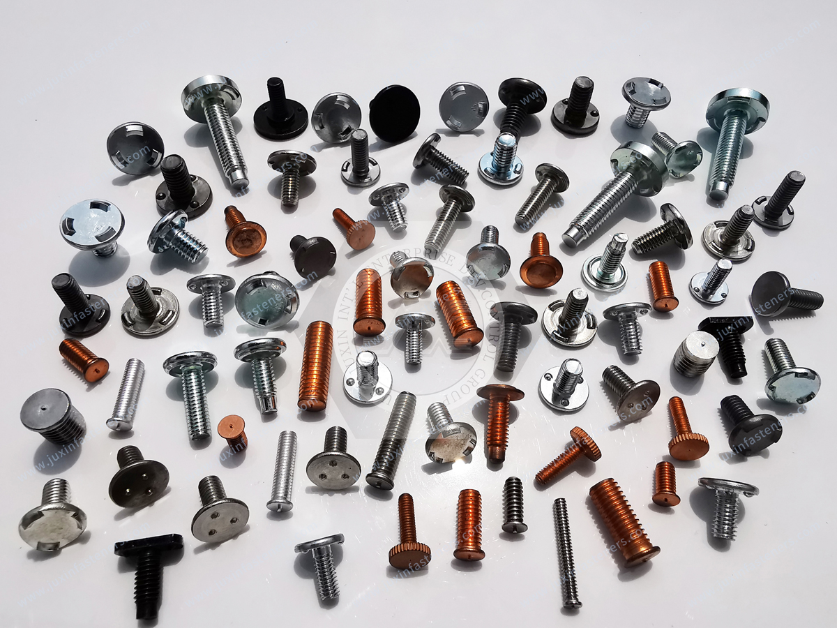
Certain commercial CD stud families use special reduced-flange configurations for automated feeding.
The actual flange geometry must be compatible with the selected feeder and welding gun.
Production Manager Considerations
For production teams, important factors include installation repeatability, equipment compatibility, cycle time,
changeover requirements, inspection, scrap, rework and delivery consistency.
Process Monitoring
Depending on the welding equipment, production records may include welding settings, cycle completion and equipment alarms.
These records support troubleshooting.
However, a completed welding cycle does not automatically prove that the finished joint meets mechanical requirements.
Pilot Production Validation
Representative samples should be used to evaluate:
Stud positioning
Weld formation
Mechanical performance
Reverse-side appearance
Tooling compatibility
Assembly fit
Production repeatability
The validation plan should reflect the actual manufacturing requirements.
Common CD Welding Defects and Practical Troubleshooting
Weak Weld Attachment
Possible causes include unsuitable welding energy, surface contamination, material incompatibility or incorrect equipment setup.
The actual cause should be established through inspection and testing.
Incomplete Fusion
Incomplete fusion may occur when joining conditions are insufficient or unstable.
The welding schedule, ignition-tip condition and surface preparation should be reviewed.
Excessive Expulsion
Excessive expulsion may be associated with inappropriate process settings or surface conditions.
The cause should be identified before adjusting parameters.
Stud Tilt
Stud misalignment may result from positioning errors, tooling problems or inconsistent stud movement.
The installation equipment and fixture arrangement should be checked.
Reverse-Side Marking
Visible marking may result from localized heating, substrate thickness or welding conditions.
Mechanical and cosmetic requirements should be assessed separately.
Thread Damage
Thread damage may occur during handling, welding or subsequent assembly.
The inspection plan should address critical thread characteristics.
Variable Weld Quality
Variation may result from changes in fastener geometry, material, surface condition or equipment setup.
A systematic investigation should compare these variables across production lots.
Quality Control and Weld Validation
Reliable production requires control of both the supplied fastener and the finished welding process.
Fastener Dimensional Inspection
Critical dimensions may include thread diameter, pitch, length, flange diameter, flange thickness, ignition-tip geometry and straightness.
Material Verification
The specified aluminum alloy should be appropriate for the intended welding process and operating environment.
Documentation requirements should be agreed with the customer.
Weld Testing
Potential evaluation methods include visual inspection, dimensional inspection, bend testing, torque-related testing, pull-off testing and other mechanical testing where appropriate.
The acceptance criteria must be defined by the application.
Fatigue and Vibration Evaluation
Where repeated loading or vibration is significant, additional evaluation may be required.
The test method should reflect the actual component and its operating conditions.
Inspection Scope
Sampling inspection or additional verification may be appropriate depending on the customer's requirements.
The inspection plan should be agreed rather than assumed.
Supplier Change Control
Changes to stud alloy, flange geometry, ignition-tip dimensions, surface condition or manufacturing process may affect welding behavior.
Critical changes should be reviewed through the OEM's applicable supplier quality procedures.
Choosing Between CD Weld Studs and Alternative Fasteners
Different fastening methods may be appropriate depending on the substrate, installation access and assembly requirements.
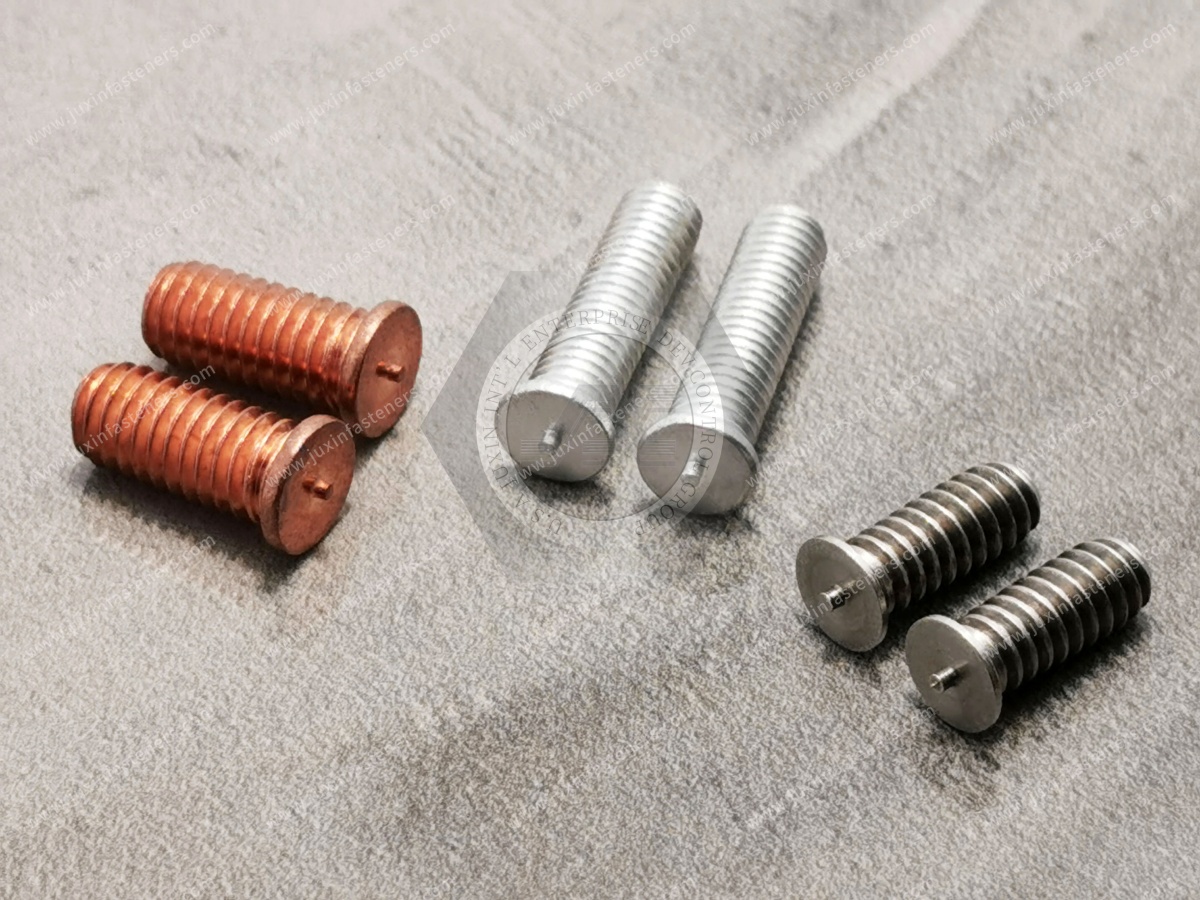
Flanged CD Weld Stud
Provides a permanent externally threaded attachment using a compatible capacitor discharge welding process.
May be suitable where the flange fits the assembly and the welded joint meets the mechanical requirements.
Non-Flanged CD Weld Stud
May be preferred where a conventional flange interferes with a nut or mating bracket.
The reduced weld-base geometry requires appropriate mechanical evaluation.
CD Weld Pin
May be suitable where an unthreaded locating or stop feature is required.
It should not be treated as identical to an externally threaded stud.
CD Weld Standoff
May be appropriate where a defined spacing function or internal thread is required.
The actual configuration must be selected according to the assembly.
Self-Clinching Stud
Uses mechanical installation in a prepared hole.
May be suitable where the sheet thickness and hardness permit installation and welding is undesirable.
Self-Clinching Standoff
Provides a defined spacing function for compatible sheet metal assemblies.
Blind Rivet Nut
Provides an internal thread through mechanical deformation.
May be useful where one-sided installation access is required.
Conventional Bolted Joint
May be preferred where the attachment requires disassembly, higher mechanical capacity or a separately qualified structural connection.
No fastening method is universally superior.
The correct choice depends on the mechanical, manufacturing, environmental and safety requirements of the assembly.
Total Installed Cost and Production Efficiency
The fastener purchase price is only one part of total installed cost.
Other factors may include welding equipment, tooling, installation time, inspection, rework, maintenance and production interruptions.
Why the Lowest Unit Price May Not Be the Best Choice
A lower-priced fastener may increase manufacturing cost if it introduces dimensional variation, feeding problems or additional inspection requirements.
Conversely, a higher-priced fastener does not automatically provide better welding performance.
The correct decision should be based on verified manufacturing results.
Flanged Versus Non-Flanged Cost Evaluation
A conventional flanged CD stud may be suitable where the flange does not interfere with the assembly.
A non-flanged configuration may be justified where additional clearance is necessary.
The selection should consider both the product price and the finished assembly requirements.
Railway OEM Supplier Development and Procurement Requirements
For purchasing teams, supplier selection requires more than comparing thread size and unit price.
The RFQ should identify the characteristics that affect welding compatibility, mechanical performance and repeat production.
Engineering Information
Product drawing and revision
Stud type
Thread system
Thread diameter and pitch
Thread tolerance class
Stud length
Flange diameter and thickness
Ignition-tip geometry
Aluminum alloy and temper
Surface finish
Dimensional tolerances
Application Information
Parent-metal alloy and temper
Sheet thickness
Welding equipment
Contact or gap welding method
Mechanical loading
Assembly torque
Surface appearance requirements
Corrosion exposure
Vibration and shock requirements
Applicable railway welding requirements
Inspection and testing requirements
Commercial Information
Prototype quantity
Sample requirements
Minimum order quantity expectations
Estimated annual demand
Packaging
Delivery schedule
Required documentation
Engineering change-control requirements
Drawing-Based Customization
Some OEM projects require nonstandard lengths, flange dimensions, materials or other features.
Technical feasibility and commercial terms depend on the actual drawing and manufacturing requirements.
Engineering Change Control
Changes to ignition-tip geometry, flange dimensions, material or surface condition may affect welding behavior.
For repeat production, changes affecting critical characteristics should be reviewed through the customer's applicable engineering and supplier quality procedures.
JUXIN FASTENERS — Aluminum CD Weld Studs and OEM Fastening Solutions
JUXIN FASTENERS supplies industrial weld studs and related fastening components for international OEM manufacturing and drawing-based applications.
Relevant product families include:
Aluminum Flanged CD Weld Studs
Flanged CD Weld Studs
Stainless Steel CD Weld Studs
Carbon Steel CD Weld Studs
Metric CD Weld Studs
Unified Inch CD Weld Studs
Non-Flanged CD Weld Studs
CD Weld Standoffs
Projection Weld Studs
Self-Clinching Fasteners
Blind Rivet Nuts
Drawing-Based Custom Fasteners
Specific dimensions, materials, surface finishes, inspection arrangements, availability and delivery terms require project-level confirmation.
Related JUXIN FASTENERS Products and Engineering Resources
Aluminum Flanged CD Weld Studs
Aluminum CD Flanged Welding Studs
Flanged CD Weld Studs — Inch / Metric
Frequently Asked Questions
What is an aluminum flanged CD weld stud?
An aluminum flanged CD weld stud is a fastener designed for capacitor discharge stud welding with a defined flange at the welding end.
Why does the stud have a flange?
The flange provides a defined weld-base region and may increase the effective joining area compared with a similar non-flanged design.
Are aluminum CD weld studs suitable for railway equipment?
They may be suitable for selected lightweight sheet metal and equipment applications when the material, welded joint and assembly requirements are compatible.
Can aluminum CD studs be used on bogies or primary carbody structures?
They should not automatically be selected for these applications. Safety-critical structural connections require application-specific engineering evaluation and qualification.
Can aluminum CD studs be welded to thin sheet metal?
Potentially, but suitability depends on the stud geometry, substrate alloy, thickness and welding procedure.
Does CD welding guarantee no reverse-side marking?
No. CD welding may help limit thermal effects, but surface appearance must be verified.
Are aluminum and steel CD weld studs interchangeable?
No. Material properties and welding compatibility differ.
Can aluminum CD studs be welded directly to steel?
Direct welding should not be assumed suitable without specific evaluation of the material combination and joining process.
Does IEC 61373:2026 certify individual weld studs?
No. IEC 61373:2026 addresses railway equipment shock and vibration testing within its scope. It does not independently establish the strength of an individual welded stud.
Does ISO 13918 automatically establish railway approval?
No. Product conformity and railway equipment qualification are separate matters.
Are metric and UNC threads interchangeable?
No. Metric, UNC and UNF threads are different systems.
Can flanged CD studs be automatically fed?
Certain configurations may be suitable for automated feeding, but compatibility depends on the actual stud and equipment.
Does passing a pull-off test prove vibration resistance?
Not necessarily. Pull-off strength and vibration performance are different characteristics.
Can JUXIN FASTENERS review custom OEM drawings?
Drawing-based requirements may be submitted for technical and commercial evaluation, including dimensions, material,
flange geometry, thread specification, inspection requirements and purchasing volume.
OEM RFQ — Aluminum Flanged CD Weld Studs for Railway Equipment Manufacturing
JUXIN FASTENERS welcomes inquiries from rolling stock manufacturers, railway interior system suppliers, onboard electrical equipment OEMs,
precision sheet metal fabricators, design engineers, manufacturing engineers, production managers and international procurement teams.
For technical evaluation and quotation, please provide the following information where applicable.
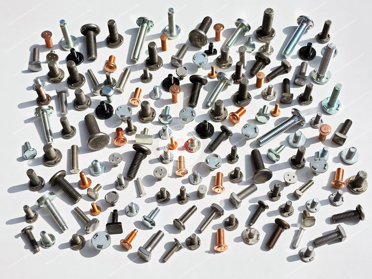
Engineering Drawings and Product Specifications
2D engineering drawing with revision
3D CAD model where available
Metric or Unified inch thread specification
Thread diameter, pitch and tolerance class
Stud length
Flange diameter and thickness
Ignition-tip geometry
Aluminum alloy and temper
Surface finish
Critical dimensional tolerances
Application and Welding Requirements
Parent-sheet alloy and thickness
Capacitor discharge welding equipment
Contact or gap welding process
Mechanical loading requirements
Assembly tightening torque
Reverse-side appearance requirements
Corrosion exposure
Vibration and shock requirements
Applicable railway welding requirements
Inspection and testing requirements
Commercial and Production Requirements
Prototype or sample quantity
Estimated annual purchasing volume
Minimum order quantity expectations
Packaging specification
Required delivery schedule
Supplier documentation requirements
Engineering change-control requirements
Complete engineering information helps reduce clarification cycles and supports accurate product evaluation and quotation.
Company: Juxin Fasteners
Website: https://www.juxinfasteners.com/
Email: info@juxinfasteners.com
For aluminum flanged capacitor discharge weld studs, inch and metric threaded studs and drawing-based fastening components for
railway equipment and lightweight sheet metal assemblies, contact JUXIN FASTENERS with your drawings and project requirements.
Our team can review the supplied specifications and discuss suitable product options, manufacturing feasibility,
inspection requirements and commercial arrangements for your OEM project.
Contact Us
Tel.:
+86 020 8621 0320
+86 020 3121 6067
E-mail:
Technical Support:
Navigation
SEND INQUIREY



