
Call Us
+86 136 6007 9809
Call Us
+86 136 6007 9809

Aug. 21, 2023
Blind rivet nuts, also called rivet nuts, rivnuts, threaded rivet inserts, or blind threaded inserts, provide a practical method for creating a reusable internal thread in sheet metal,
profiles, tubes, panels, and other assemblies where access to the rear side is limited or unavailable.
Unlike a conventional welded nut, a blind rivet nut can normally be installed from one side of the workpiece.
The installation tool deforms the rivet nut body behind the parent material, creating a mechanical connection while leaving an internal thread available for a mating screw or bolt.
This makes blind rivet nuts particularly relevant to automotive body structures, EV battery enclosures, electrical cabinets,
HVAC equipment, industrial machinery, electronics housings, rail equipment, robotics, communications equipment, renewable-energy systems, and general sheet-metal fabrication.
For engineers, however, selecting a blind rivet nut is not simply a matter of choosing M4, M5, M6, or another thread size.
The joint is influenced by the parent material, sheet thickness, prepared hole, rivet nut body geometry, grip range,
installation method, installation stroke, deformation behavior, mating screw, assembly torque, service load, corrosion environment, and required service life.
For procurement teams, supplier selection also requires control of material, finish, dimensions, thread quality, inspection requirements, packaging, documentation, annual demand, and application-specific quality requirements.
JUXIN FASTENERS supplies blind rivet nut solutions for industrial OEM and custom fastening applications, with product selection based on the actual assembly rather than thread size alone.
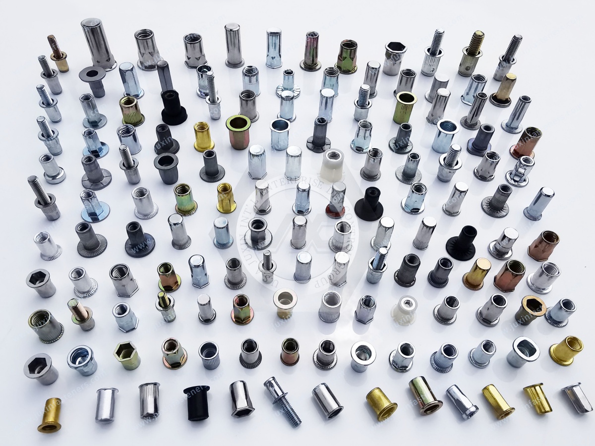
A blind rivet nut is a threaded insert designed to be installed into a prepared hole from one accessible side of a workpiece.
Before installation, the body is generally cylindrical, knurled, partially hexagonal, or otherwise shaped according to the required anti-rotation and installation characteristics.
During installation, a threaded mandrel or tool engages the internal thread and draws the rivet nut body into a controlled deformation.
The deformed portion forms a mechanical clamping zone behind the sheet.
The result is a captive threaded connection that can accept a mating screw or bolt.
This architecture is particularly useful when the reverse side of the panel cannot be reached by an operator or installation tool.
Blind rivet nuts solve several common assembly problems.
A sheet-metal panel may be too thin to provide sufficient thread engagement for direct tapping.
A welded nut may introduce heat, distortion, weld spatter, surface-treatment damage, or additional manufacturing operations.
A conventional nut may require access to both sides of the assembly.
A blind rivet nut addresses these constraints through single-sided mechanical installation.
Typical engineering objectives include:
Creating a reusable threaded attachment point.
Adding threads to thin sheet metal.
Installing threads into closed or partially enclosed structures.
Avoiding welding operations.
Supporting modular assembly.
Allowing service access and repeated screw removal.
Simplifying assembly where rear-side access is restricted.
Supporting enclosure, bracket, panel, and equipment construction.
The fundamental characteristic of a blind rivet nut is single-sided installation.
The installer places the rivet nut into the prepared hole.
The installation tool engages the internal thread and pulls the body relative to the flange.
The body then deforms in the designated collapse zone.
The resulting deformation forms a mechanical lock behind the parent material.
The flange remains on the accessible side of the workpiece.
The internal thread remains available for the final mating screw.
The exact deformation pattern depends on rivet nut geometry, material, grip range, hole size, installation stroke, installation force, and parent-material characteristics.
Therefore, the installation process should be treated as a joint-design variable rather than simply a tooling operation.
A blind rivet nut normally contains several functional areas:
Head or flange.
Threaded section.
Body or shank.
Collapse zone.
Knurling or anti-rotation geometry where applicable.
Closed-end section where applicable.
The collapse zone is particularly important because it is the portion of the body that deforms behind the sheet.
Its geometry affects how the rivet nut forms the rear-side mechanical lock.
A rivet nut should therefore be selected according to its intended grip range rather than by thread size alone.
Grip range describes the parent-material thickness range for which a particular rivet nut design can be installed correctly.
It should not be confused with the nominal thickness of the complete assembly.
For example, an assembly may contain:
One sheet.
Two overlapping sheets.
A coated sheet.
A sheet plus gasket.
A composite panel.
A formed bracket.
A stack-up with multiple layers.
The effective material stack must be evaluated before selecting the rivet nut.
A supplier RFQ should therefore identify the actual material thickness or stack-up rather than only stating "thin sheet."
A common sourcing mistake is to specify only the sheet thickness.
For a single 1.5 mm sheet, the effective grip is relatively straightforward.
For two overlapping panels, however, the supplier needs to understand whether the rivet nut is intended to grip the combined stack or a specific layer.
Paint, powder coating, plating, adhesive films, insulation layers, seals, and other surface treatments can also influence the actual assembly stack.
For this reason, the effective grip requirement should be confirmed from the finished assembly condition.
The prepared hole is not merely a manufacturing detail.
It is part of the rivet nut joint.
If the hole is too small, the rivet nut may not insert correctly or may damage the parent material during installation.
If the hole is too large, the available material engagement may be reduced and anti-rotation performance can be affected.
The correct hole diameter must therefore be based on the selected rivet nut design and the manufacturer's specified installation requirements.
For OEM production, the hole diameter should be controlled on the production drawing where the application requires it.
Different rivet nut body geometries provide different resistance to rotation.
A round smooth body primarily relies on the deformation and frictional relationship between the insert and parent material.
Knurled bodies provide additional mechanical interaction with the hole.
Hexagonal or partially hexagonal bodies can provide a stronger geometric interface against rotation when the mating hole and parent material are correctly specified.
However, a hex body does not automatically eliminate all spin-out risk.
The final performance depends on:
Body geometry.
Hole geometry.
Hole size.
Parent-material strength.
Sheet thickness.
Installation quality.
Assembly torque.
Service loading.
This distinction is important when designing high-torque or vibration-sensitive applications.
Rivet nut performance should not be described by a single generic "strength" number.
Several different failure modes can occur.
Pull-out occurs when axial loading causes the installed rivet nut to move out of the parent material or the surrounding sheet to deform.
Torque-out refers to failure associated with rotational loading between the insert and parent material.
Spin-out occurs when the installed rivet nut rotates during screw installation or removal.
The rivet nut itself may remain intact while the surrounding sheet deforms or fails.
These failure modes should be considered separately during engineering validation.
A blind rivet nut does not operate independently.
The final joint includes the rivet nut, mating screw, panel, washers or spacers where applicable, and the assembled components.
The mating screw affects assembly torque and service loading.
Thread compatibility must be confirmed.
The screw material and surface treatment can also affect corrosion compatibility and friction behavior.
For example, combining dissimilar metals in a humid or chemically aggressive environment may require additional corrosion evaluation.
Open-end blind rivet nuts have a through-threaded structure.
They are commonly selected where the application does not require a closed end.
Typical applications include:
Electrical cabinets.
Sheet-metal housings.
Automotive brackets.
Machinery covers.
Control panels.
Equipment frames.
HVAC assemblies.
General industrial enclosures.
Open-end designs can provide straightforward access for the mating screw and are available in different body and flange configurations.
Closed-end blind rivet nuts have a closed distal end.
They can be considered when the design requires the threaded insert to close the internal passage of the component.
Applications may include:
Enclosures.
Battery-related structures.
Equipment exposed to environmental contamination.
Fluid-adjacent assemblies.
Applications where the internal thread needs a closed-end configuration.
However, closed-end construction should not automatically be interpreted as waterproof or IP-rated.
A sealing rivet nut, gasket, coating, joint interface, panel, and enclosure design must be evaluated together when environmental sealing is required.
This distinction is important in engineering specifications.
A closed-end rivet nut closes the end of the insert.
That does not automatically mean the complete assembly is waterproof.
Environmental sealing can depend on:
Rivet nut design.
Seal geometry.
Seal material.
Panel interface.
Surface condition.
Installation deformation.
Mating screw.
Washer or gasket.
Enclosure construction.
Validation testing.
If an application has a specific IP requirement, the complete assembly should be validated against the applicable enclosure or equipment requirements.
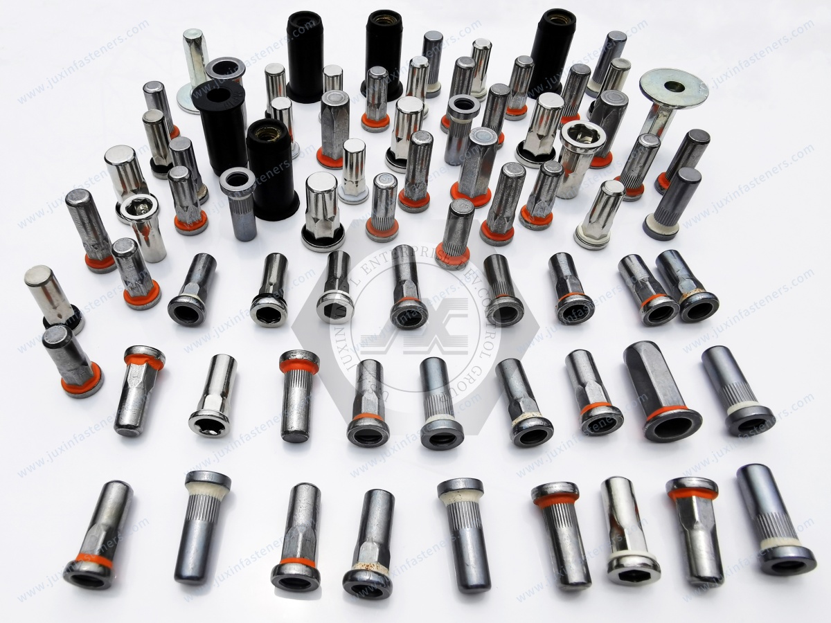
Sealing rivet nuts may incorporate a sealing feature designed to reduce the path through the installation interface.
They can be considered for applications where contamination or moisture ingress is a design concern.
Typical applications include:
EV battery enclosures.
Electrical equipment.
Outdoor control cabinets.
HVAC equipment.
Industrial equipment.
Automotive components.
Fluid-adjacent housings.
The correct seal material and geometry should be selected according to the operating environment.
Extended blind rivet nuts use a longer body or deformation zone to accommodate applications that cannot be addressed effectively by a standard short-body design.
They can be useful when:
The material stack is relatively thick.
Multiple layers must be considered.
A deeper installation geometry is required.
A standard rivet nut cannot achieve the required deformation position.
Composite or formed structures create unusual grip conditions.
An extended body should not be selected solely because the panel is "thick."
The actual grip requirement and deformation geometry should be evaluated.
A standard rivet nut may not be suitable when:
The required grip exceeds its specified range.
The panel is unusually soft.
The assembly contains multiple layers.
The hole has restricted geometry.
High torque resistance is required.
Repeated assembly cycles are expected.
Environmental sealing is important.
Corrosion compatibility is critical.
The installation location requires a specific head profile.
In such cases, a custom or application-specific rivet nut configuration may be more appropriate.
Hexagonal and semi-hex body configurations can increase mechanical resistance to rotation when matched with a suitable hole.
They are often considered for assemblies where higher torque transfer or improved anti-rotation behavior is required.
Typical applications include:
Automotive brackets.
Industrial machinery.
Structural sheet-metal assemblies.
Equipment frames.
High-vibration components.
Serviceable enclosures.
The parent sheet must still be strong enough to support the required joint.
Knurled bodies use external surface geometry to increase mechanical interaction with the parent material.
They are commonly considered where additional resistance to rotation is required without using a full hexagonal hole.
The effectiveness of knurling depends on the parent material, hole size, installation process, and final assembly load.
Knurling should therefore be evaluated as part of the complete joint rather than treated as an independent performance guarantee.
Thin sheet metal is one of the most common reasons engineers consider blind rivet nuts.
Directly tapping a very thin sheet can provide limited thread engagement.
A rivet nut creates a separate threaded component with greater available thread depth than the sheet itself.
This is useful for:
Enclosure panels.
Electrical cabinets.
Automotive body brackets.
HVAC housings.
Equipment covers.
Control boxes.
Electronics assemblies.
The parent sheet remains a critical part of the joint.
The same rivet nut can behave differently in different parent materials.
Important variables include:
Carbon steel.
Stainless steel.
Aluminum.
Coated steel.
Painted sheet.
Composite panels.
Soft metals.
Formed sheet.
Multi-layer structures.
A rivet nut selected for steel should not automatically be assumed to provide identical performance in aluminum or composite material.
Aluminum is widely used where weight reduction and corrosion considerations are important.
However, aluminum has different mechanical behavior from steel.
The designer should consider:
Parent-sheet strength.
Sheet thickness.
Hole deformation.
Galvanic compatibility.
Thermal expansion.
Rivet nut material.
Mating screw material.
Surface treatment.
For aluminum panels, material compatibility should be considered at the system level.
Stainless steel rivet nuts may be considered when corrosion resistance, appearance, or material compatibility is important.
Typical applications include:
Food-service equipment.
HVAC equipment.
Outdoor equipment.
Industrial machinery.
Stainless enclosures.
Automotive components.
Equipment exposed to corrosive environments.
The exact stainless grade should be selected according to the application and confirmed against the customer's specification.
Carbon steel rivet nuts are widely used for general industrial sheet-metal applications.
They can offer a practical combination of mechanical performance, availability, and cost.
Surface treatment may be specified according to the environmental requirements.
For example, zinc-based finishes may be considered for corrosion protection in suitable applications.
The exact coating, thickness, appearance, and environmental performance should be defined in the procurement specification.
Aluminum rivet nuts can be considered when weight reduction is important.
They may be relevant to:
Automotive structures.
EV components.
Rail equipment.
Electronics.
Lightweight machinery.
Aerospace-related equipment.
Aluminum sheet-metal assemblies.
Lower material density does not automatically mean a lower total joint mass or higher joint efficiency.
The complete assembly must still meet its mechanical and environmental requirements.
Selecting the rivet nut material should consider more than the insert itself.
Engineers should evaluate:
Parent material.
Mating screw.
Surface treatment.
Operating temperature.
Humidity.
Chemical exposure.
Outdoor exposure.
Galvanic compatibility.
Required service life.
Assembly environment.
This approach reduces the risk of selecting a technically suitable insert that becomes unsuitable after assembly with different materials.
When dissimilar metals are joined, galvanic corrosion can become a system-level consideration in the presence of an appropriate electrolyte.
For example, an aluminum panel combined with a steel or stainless-steel fastener may require additional evaluation depending on the environment.
Potential controls include:
Material selection.
Compatible coatings.
Isolation layers.
Sealants.
Surface treatments.
Environmental control.
No single rivet nut material should be described as universally corrosion-proof for every assembly.
Surface treatment can affect:
Corrosion resistance.
Appearance.
Friction.
Electrical contact.
Environmental compatibility.
Galvanic behavior.
Assembly characteristics.
The finish should therefore be specified together with the base material.
A procurement drawing should identify the required coating or treatment where it is application-critical.
The internal thread is the functional interface with the final screw.
Thread inspection can include appropriate gauges and dimensional checks according to the customer's specification.
Important parameters may include:
Thread size.
Pitch.
Thread class or tolerance.
Thread depth.
Effective thread engagement.
Internal contamination.
Damage or deformation.
Thread quality should be controlled consistently throughout production.
The flange supports the rivet nut against the accessible side of the parent material.
Different flange configurations may be used according to assembly requirements.
Potential considerations include:
Head diameter.
Head thickness.
Flatness.
Countersunk interface.
Panel clearance.
Cosmetic requirements.
Load distribution.
A flush or countersunk head may be preferred where the assembly requires a reduced protrusion.
Countersunk rivet nuts are useful where the surrounding assembly requires a flush or reduced-profile installation.
The countersink geometry must match the parent panel.
If the countersink is incorrect, the flange may not seat correctly.
This can affect installation consistency and the final position of the threaded connection.
Therefore, the rivet nut and mating countersink should be specified as a matched interface.
Installation stroke and installation force are important process variables.
Too little deformation may result in an incomplete mechanical lock.
Excessive deformation can damage the insert or parent material.
The correct installation window depends on:
Rivet nut geometry.
Material.
Grip range.
Sheet thickness.
Hole size.
Installation tooling.
Parent material.
Production teams should establish the installation process around the selected rivet nut rather than applying a generic setting value to every product.
Blind rivet nuts can be installed using different tool configurations depending on production requirements.
Manual tools may be suitable for lower-volume work.
Powered installation tools can improve production consistency where larger volumes are involved.
The tool must be compatible with the rivet nut thread and installation method.
For automated or semi-automated assembly, the supplier and customer should confirm the required tool interface and process window.
A rivet nut may meet dimensional requirements before installation and still produce inconsistent results if the installation process is poorly controlled.
Production variables can include:
Hole quality.
Tool alignment.
Mandrel engagement.
Installation stroke.
Installation force.
Tool wear.
Sheet thickness.
Operator technique.
Material variation.
For high-volume programs, the installation process should therefore be considered part of supplier and manufacturing validation.
The installation tool should generally remain aligned with the rivet nut axis.
Angular loading can affect the deformation process and may create uneven contact with the panel.
In production environments, fixture design and access to the installation point can therefore influence joint consistency.
This is particularly important for deep enclosures, angled brackets, and restricted assembly spaces.
Thin sheet metal can deform during installation if the process is not correctly matched to the panel.
Potential symptoms include:
Panel distortion.
Local indentation.
Flange seating problems.
Hole enlargement.
Surface damage.
The solution is not always a stronger rivet nut.
The engineer may need to reconsider:
Rivet nut geometry.
Grip range.
Installation force.
Hole diameter.
Panel thickness.
Local reinforcement.
Blind rivet nuts are widely used in equipment exposed to vibration.
However, vibration resistance is a joint-design issue.
The engineer should consider:
Preload.
Mating screw.
Joint stiffness.
Panel thickness.
Anti-rotation geometry.
Surface friction.
Assembly torque.
Service vibration.
Repeated loading.
A rivet nut should not be described as "vibration-proof" without application-specific validation.
One important advantage of a threaded rivet nut is the ability to provide a reusable threaded connection.
This is useful for:
Maintenance panels.
Service covers.
Electronics housings.
Automotive components.
Industrial equipment.
Replaceable modules.
However, repeated assembly can introduce wear to both the rivet nut thread and mating screw.
For frequently serviced assemblies, thread material, lubrication requirements, screw material, torque specification, and expected service cycles should be evaluated.
Automotive applications can include:
Body brackets.
Interior components.
Underbody structures.
Seat-related components.
Trim supports.
Battery-related structures.
Electronic modules.
Access panels.
Automotive applications can impose demanding requirements for vibration, corrosion, assembly speed, dimensional consistency, and traceability.
For related automotive fastening requirements, JUXIN FASTENERS also supplies industrial and automotive bolts and nuts as part of a broader fastening portfolio.
EV battery systems often combine thin metal structures, limited backside access, weight constraints, sealing requirements, and serviceability considerations.
Blind rivet nuts can be used for mounting:
Covers.
Brackets.
Cable-management components.
Electrical components.
Sensors.
Protective panels.
Service-related components.
Where environmental sealing is required, the rivet nut should be treated as one component of the complete enclosure sealing system.
For battery enclosure applications requiring sealing, the difference between a conventional open-end rivet nut and a sealing or closed-end design should be evaluated during engineering development.
Electrical cabinets and control enclosures frequently use sheet metal with limited rear-side access.
Blind rivet nuts can provide mounting threads for:
Terminal components.
Control modules.
Brackets.
Cable-management hardware.
Covers.
Internal support structures.
Stainless steel, carbon steel, and other materials can be considered according to environmental and electrical requirements.
Electronics housings often require compact threaded mounting points without adding large welded components.
Important considerations include:
Panel thickness.
Available installation space.
Head profile.
Thread size.
Cosmetic requirements.
Corrosion environment.
Assembly torque.
Repeated service access.
Compact flange and body configurations can be useful where internal space is limited.
Industrial machinery commonly combines sheet-metal guards, covers, brackets, frames, and service panels.
Blind rivet nuts can provide practical threaded mounting points for these components.
They can be used for:
Machine guards.
Access covers.
Electrical boxes.
Brackets.
Sensor mounts.
Protective panels.
Serviceable components.
For heavily loaded structural joints, however, the engineer should verify whether a rivet nut is appropriate for the actual load path rather than assuming every sheet-metal connection can use the same insert.
HVAC systems frequently use formed sheet metal and enclosed equipment structures.
Blind rivet nuts can support:
Access panels.
Brackets.
Control components.
Fan-related assemblies.
Electrical components.
Service covers.
Material and surface treatment should be selected according to indoor, outdoor, humidity, condensation, and chemical exposure conditions.
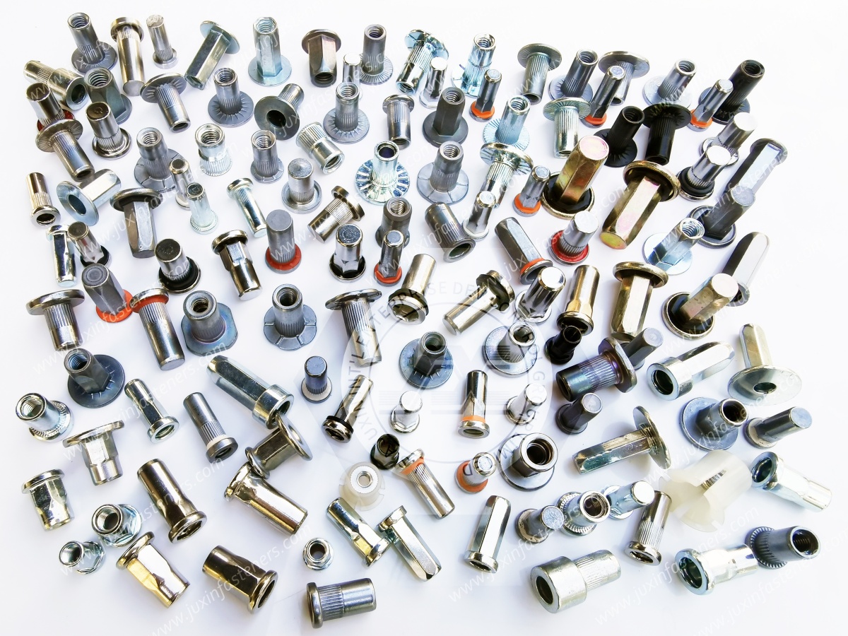
Rail and transportation equipment may require threaded inserts in sheet-metal structures where backside access is restricted.
Relevant engineering considerations can include:
Vibration.
Corrosion.
Weight.
Serviceability.
Installation access.
Material compatibility.
Inspection requirements.
The final specification should be based on the applicable customer and transportation-industry requirements.
Robotic equipment frequently requires compact brackets and removable covers.
Blind rivet nuts can be used for:
Sensor brackets.
Cable-management components.
Protective covers.
Actuator-related brackets.
Electronics housings.
Machine guarding.
Because robots can experience repeated motion and vibration, the complete joint should be evaluated for loosening, fatigue, and serviceability.
Communications equipment often uses thin sheet-metal enclosures and modular internal components.
Blind rivet nuts can provide attachment points for:
PCB support hardware.
Brackets.
Cable routing components.
Equipment covers.
Internal mounting plates.
Electronics modules.
Material selection should account for the enclosure environment and any electrical or electromagnetic design requirements.
Renewable-energy equipment can include electrical cabinets, control systems, structural panels, equipment housings, and serviceable modules.
Blind rivet nuts can be considered where single-sided installation and threaded service access are useful.
For outdoor equipment, corrosion protection and environmental exposure should be evaluated together with the complete assembly.
Lightweight structures may use aluminum panels, composite structures, or thin formed components.
Blind rivet nut selection in these applications requires careful attention to:
Parent material.
Local reinforcement.
Hole quality.
Weight.
Corrosion compatibility.
Service loads.
Installation access.
Customer-specific aerospace requirements.
The insert should be specified according to the actual application and approved material or process requirements rather than selected only by nominal thread size.
Composite panels can behave differently from metallic sheet.
The engineer should consider:
Local crushing.
Hole quality.
Delamination risk.
Load distribution.
Insert geometry.
Installation force.
Reinforcement strategy.
A standard metal-sheet rivet nut should not automatically be assumed suitable for every composite structure.
Application-specific validation is recommended.
A common procurement shortcut is:
"M6 means stronger than M5."
That is not sufficient for rivet nut selection.
Joint behavior can depend on:
Rivet nut material.
Body geometry.
Grip range.
Parent material.
Sheet thickness.
Hole diameter.
Installation quality.
Mating screw.
Applied load.
The thread size defines the screw interface, but it does not independently define the performance of the entire joint.
Selecting a stronger rivet nut does not automatically improve the complete assembly.
If the parent sheet is too weak, the surrounding panel may deform before the insert reaches its theoretical capacity.
If the hole is oversized, anti-rotation performance may be reduced.
If the installation process is inconsistent, the theoretical properties may not be achieved.
Therefore, the correct engineering question is:
"What is the required joint performance in the actual parent material and assembly?"
rather than:
"What is the strongest rivet nut available?"
One of the most important design insights is that the hole should be treated as part of the fastening system.
The final joint consists of:
Rivet nut + hole + parent material + installation process + mating screw + service load.
Changing any one of these variables can affect the final result.
This is why supplier drawings should clearly identify the recommended hole diameter and installation requirements.
Grip range describes the condition under which the rivet nut can develop its intended deformation.
It is not simply a marketing description of "maximum sheet thickness."
For multi-layer assemblies, coated panels, insulation layers, or formed structures, the effective grip must be calculated from the actual assembly stack.
This is especially important when purchasing large volumes because an incorrect grip selection can create systematic production problems.
A rivet nut may demonstrate acceptable rotational resistance while having insufficient axial resistance.
Conversely, an insert may have adequate pull-out resistance but inadequate torque-out resistance.
Therefore, application testing should identify which loading modes are relevant.
This is particularly important for:
Brackets.
Structural panels.
High-torque screws.
Vibration-loaded assemblies.
Service covers.
Heavy equipment.
An anti-rotation feature only works as intended when the hole and parent material support it.
A hex or semi-hex body placed into an unsuitable hole may not achieve the expected geometric engagement.
Similarly, a knurled body installed into an oversized hole may not provide the intended resistance to rotation.
The mating hole is therefore part of the anti-rotation design.
A practical blind rivet nut selection process can follow this sequence:
Identify the parent material.
Identify the actual material thickness or stack-up.
Identify the required internal thread.
Determine the required grip range.
Define the hole diameter.
Determine whether anti-rotation is required.
Select open-end or closed-end construction.
Evaluate whether a sealing feature is required.
Select body and flange geometry.
Select material.
Select surface treatment.
Confirm mating screw compatibility.
Define installation tooling.
Identify relevant service loads.
Validate the complete joint.
Define inspection and documentation requirements.
Release the production RFQ.
A professional procurement specification should include as many of the following as applicable:
Part number.
Thread size.
Thread specification.
Head or flange type.
Body geometry.
Open or closed end.
Grip range.
Parent material.
Hole diameter.
Material.
Surface treatment.
Color or appearance requirement.
Mating screw specification.
Application environment.
Corrosion requirement.
Installation method.
Inspection requirements.
Packaging.
Traceability requirements.
Required documentation.
Annual quantity.
Forecast quantity.
Delivery requirements.
The more complete the RFQ, the lower the risk of supplier assumptions.
Procurement and supplier-development teams should ask:
What blind rivet nut geometries are available?
Which materials are available?
What grip ranges are available?
What hole diameter is recommended?
Is the body knurled, hexagonal, or another configuration?
Is an extended-body version available?
Are closed-end or sealing configurations available?
What surface treatments are available?
What inspection method is used for the internal thread?
What dimensional documentation is available?
Can the supplier work from customer drawings?
What packaging and traceability options are available?
What sample and production approval process is applicable?
These questions help separate a catalog distributor from a supplier capable of supporting an OEM-specific fastening program.
Custom blind rivet nuts may be required when standard dimensions cannot satisfy the application.
A supplier drawing should ideally define:
Thread.
Body diameter.
Overall length.
Grip range.
Flange diameter.
Flange thickness.
Hole requirement.
Body geometry.
Material.
Surface treatment.
Critical dimensions.
Inspection requirements.
A 2D drawing is particularly useful for dimensional control.
A 3D model can also help engineers evaluate installation clearance and assembly interfaces when available for the specified product.
Quality control should reflect the characteristics that are critical to the customer's application.
Possible inspection items include:
Overall dimensions.
Flange dimensions.
Body diameter.
Thread size.
Thread condition.
Grip-related dimensions.
Material identification.
Surface treatment.
Appearance.
Packaging quantity.
Traceability.
Where customer specifications require special testing, those requirements should be agreed before production.
Material documentation requirements vary by application.
For controlled OEM programs, procurement teams may request documentation related to:
Material grade.
Heat or lot traceability.
Surface treatment.
Inspection results.
Certificate requirements.
Where EN 10204 documentation is specified by the customer, the exact certificate type should be stated in the purchasing specification.
Documentation should never be assumed to be included automatically unless it has been agreed as part of the order requirements.
For international OEM supply, procurement teams may specify environmental requirements such as:
RoHS.
REACH.
Customer-specific restricted-substance requirements.
Applicable conflict-minerals reporting requirements.
Surface-treatment restrictions.
Packaging requirements.
The exact compliance documentation should be based on the customer's applicable market and contractual requirements.
A low unit price does not necessarily produce the lowest total assembly cost.
Total cost can include:
Component price.
Installation labor.
Tooling.
Scrap.
Panel damage.
Rework.
Supplier quality issues.
Inventory.
Packaging.
Logistics.
Assembly cycle time.
Field service.
For high-volume OEM programs, selecting the correct rivet nut geometry at the design stage can therefore have a greater commercial impact than a small difference in unit price.
Procurement teams should communicate:
Prototype quantity.
Initial production quantity.
Monthly demand.
Annual demand.
Forecast horizon.
Packaging requirements.
Delivery location.
Required safety stock where applicable.
Engineering-change requirements.
This allows the supplier to evaluate production planning and supply requirements more accurately.
Blind rivet nuts and welded nuts solve related but different assembly problems.
Welded nuts require a welding process and access to the appropriate manufacturing operation.
Blind rivet nuts can generally be installed mechanically from one accessible side.
The choice may depend on:
Sheet thickness.
Welding access.
Heat sensitivity.
Coating condition.
Production process.
Assembly volume.
Serviceability.
Required joint performance.
For coated or finished panels, avoiding a welding operation may be an important manufacturing consideration.
Direct tapping creates threads directly in the parent material.
This may be appropriate when sufficient material thickness and thread engagement are available.
A blind rivet nut becomes more attractive when:
The sheet is thin.
Rear-side access is restricted.
A reusable threaded connection is required.
The panel cannot provide sufficient thread engagement.
Welding is undesirable.
The correct choice should be based on the complete manufacturing and service requirements.
A conventional nut can provide a strong threaded connection but normally requires access to the rear side during assembly.
Blind rivet nuts are specifically valuable where rear-side access is unavailable.
This makes them particularly useful for:
Closed enclosures.
Tubular structures.
Box sections.
Finished panels.
Large equipment housings.
The choice should still consider load path, installation access, cost, and service requirements.
JUXIN FASTENERS supports industrial OEM sourcing for blind rivet nut applications involving sheet-metal assemblies and specialized fastening requirements.
Product selection can include consideration of:
Open-end blind rivet nuts.
Closed-end configurations.
Sealing rivet nut requirements.
Extended-body designs.
Anti-rotation body geometries.
Steel rivet nuts.
Stainless steel rivet nuts.
Aluminum rivet nuts.
Custom dimensions.
Application-specific finishes.
The correct configuration depends on the customer's drawing, assembly, environment, and production requirements.
Blind rivet nuts are often used together with other fastening components in complete industrial assemblies.
For broader structural fastening requirements, JUXIN FASTENERS also supplies high-strength bolts and nuts.
For automotive and machinery programs requiring conventional threaded hardware, related industrial and automotive bolts and nuts can be evaluated.
For precision metal components used alongside threaded fastening systems, see stainless steel CNC machining parts.
For lightweight non-metallic mounting and cable-management requirements, see automotive plastic fasteners.
A practical OEM RFQ should provide the following information:
Application:
Describe what the rivet nut will mount.
Parent Material:
Steel, stainless steel, aluminum, composite, or other material.
Material Thickness:
Provide the actual sheet thickness or stack-up.
Thread:
For example M4, M5, M6, M8, or the required inch thread.
Grip Range:
Provide the required material thickness range.
Hole:
Provide the existing hole diameter or required hole specification.
Body:
Round, knurled, hex, semi-hex, extended, or custom.
End Configuration:
Open end, closed end, or sealing configuration.
Material:
Carbon steel, stainless steel, aluminum, or specified alloy.
Surface Treatment:
Provide the required coating or finish.
Mating Screw:
Provide screw material, size, coating, and relevant assembly requirements where available.
Environment:
Indoor, outdoor, humidity, chemicals, temperature, vibration, or other service conditions.
Quantity:
Prototype, pilot, monthly demand, annual volume, and forecast.
Documentation:
State required inspection reports, material documentation, traceability, compliance documents, or customer-specific requirements.
Before approving a rivet nut for a critical OEM application, the engineering team should consider validating the complete joint.
Depending on the application, validation may examine:
Installation consistency.
Pull-out behavior.
Torque-out behavior.
Spin-out behavior.
Parent-sheet deformation.
Mating screw compatibility.
Corrosion behavior.
Environmental exposure.
Vibration.
Repeated assembly.
Dimensional stability.
The exact test method and acceptance criteria should be defined by the customer and application requirements.
The most effective selection method is to start with the assembly rather than the catalog.
Ask:
What material is the panel?
How thick is the panel or stack?
Is rear-side access available?
What thread is required?
What load does the joint carry?
Is rotation resistance important?
Is repeated removal required?
Is environmental sealing required?
What corrosion environment exists?
What mating screw will be used?
What installation tool will be used?
What inspection and documentation are required?
These questions usually narrow the correct product configuration much faster than searching by thread size alone.
For procurement teams, the sourcing process should connect the technical requirement to the commercial requirement.
A useful sequence is:
Application → Drawing → Specification → Prototype → Validation → Supplier approval → Production quotation → Quality agreement → Production → Delivery.
This reduces the risk of purchasing a visually similar rivet nut that does not match the actual engineering requirement.
A drawing gives the supplier a much clearer technical target.
It reduces ambiguity around:
Thread.
Dimensions.
Grip.
Flange.
Material.
Finish.
Hole.
Critical characteristics.
For custom blind rivet nuts, a customer drawing is often the most efficient starting point for technical review.
Blind rivet nuts should ideally be considered during product design rather than added after the sheet-metal structure is finalized.
Early consideration allows engineers to optimize:
Hole location.
Flange clearance.
Tool access.
Panel thickness.
Grip range.
Fastener size.
Mating screw.
Service access.
Reinforcement.
This can reduce redesign and production problems later in the program.
The central engineering principle is simple:
A blind rivet nut is not an isolated component.
Its real performance comes from the interaction of the insert, hole, parent material, installation process, mating screw, assembly torque, and service environment.
This is why two applications using the same M6 rivet nut can require different designs and produce different results.
An effective RFQ does not need unnecessary information.
It needs the information that changes the engineering decision.
For blind rivet nuts, the most valuable inputs are usually:
Thread.
Grip.
Parent material.
Thickness.
Hole.
Body geometry.
End configuration.
Material.
Finish.
Application load.
Environment.
Quantity.
Documentation.
Providing these items allows the supplier to respond with a more technically relevant proposal.
For international OEM programs, supplier evaluation can extend beyond product price.
Procurement and supplier-development teams may consider:
Manufacturing consistency.
Technical communication.
Drawing control.
Material traceability.
Inspection capability.
Packaging.
Change control.
Delivery performance.
Documentation.
Regulatory requirements.
Long-term supply capability.
JUXIN FASTENERS works with customers based on the specific requirements of each program rather than assuming that one standard configuration fits every application.
If you are developing a sheet-metal, enclosure, automotive, EV, machinery, electrical, HVAC, electronics, rail, robotics, or industrial equipment assembly, provide your drawing or fastening requirements to JUXIN FASTENERS.
Useful information includes:
2D drawing.
3D model where available.
Thread size.
Sheet thickness.
Parent material.
Hole diameter.
Required grip range.
Open or closed end.
Anti-rotation requirement.
Material.
Surface treatment.
Mating screw.
Annual quantity.
Application environment.
For OEM sourcing and engineering inquiries:
Email: info@juxinfasteners.com
JUXIN FASTENERS can evaluate the specified blind rivet nut requirements and develop the appropriate product configuration based on the customer's application,
drawing, technical specification, and procurement requirements.
 MORE NEWS

Sep. 25, 2026

Sep. 25, 2026

Sep. 25, 2026
Contact Us
Tel.:
+86 020 8621 0320
+86 020 3121 6067
E-mail:
Technical Support:
Navigation
SEND INQUIREY