
Call Us
+86 136 6007 9809
Call Us
+86 136 6007 9809

Aug. 21, 2023
Modern elevator manufacturing combines thin-gauge sheet metal, stainless steel architectural panels, formed brackets, equipment enclosures, door assemblies, interior trim, and serviceable components.
These assemblies often require threaded attachment points where access to the rear side of the panel is restricted.
Traditional direct tapping may provide insufficient thread engagement in thin sheet metal. Welding can introduce heat, distortion, surface discoloration,
additional finishing requirements, and process constraints that are undesirable for visible architectural panels.
Blind rivet nuts provide another approach.
Installed from one accessible side, a blind rivet nut creates an internal threaded attachment point by mechanically deforming its body behind the parent sheet.
For elevator manufacturing, however, the product should not be selected simply by thread size.
Head geometry, head thickness, bearing area, body configuration, grip range, hole diameter, parent material, installation method, corrosion environment, surface appearance, and mating screw all influence the final assembly.
JUXIN FASTENERS supplies blind rivet nut solutions for industrial OEM applications, including configurations that can be evaluated for elevator car panels, door-related sheet-metal assemblies, equipment enclosures, architectural components, and other applications requiring single-sided threaded fastening.
This guide focuses on the engineering principles behind reinforced-head elevator rivet nuts and the information procurement and engineering teams should provide when sourcing them.

An elevator blind rivet nut is a threaded insert designed to be installed into a prepared hole from one accessible side of a panel or structure.
The installation tool engages the internal thread and pulls the rivet nut body into a controlled deformation.
The deformed body forms a mechanical lock behind the sheet.
The flange or head remains on the accessible side.
After installation, the internal thread provides a reusable connection for a mating screw or bolt.
This architecture is particularly useful for elevator assemblies where the rear side of a panel may be enclosed, inaccessible, finished, or difficult to reach during production.
Elevator manufacturers may encounter several fastening constraints at the same time.
A stainless steel interior panel may be too thin for reliable direct tapping.
A finished decorative surface may be unsuitable for a welding operation.
A closed structural section may prevent access for placing a conventional nut.
A service panel may require repeated removal and reinstallation.
A blind rivet nut can address these situations by providing a mechanically installed internal thread.
Potential advantages include:
Single-sided installation.
Reusable threaded attachment.
No welding heat during installation.
Compatibility with thin sheet-metal structures.
Installation into enclosed or restricted-access areas.
Flexible body and head configurations.
Suitability for OEM panel and equipment assemblies.
The final suitability still depends on the actual joint requirements.
The reinforced-head concept in a blind rivet nut refers to a head or flange configuration designed with greater material or bearing geometry than a lighter standard configuration.
The purpose is not simply to make the component heavier.
A reinforced head can be considered when the interface between the fastener and parent sheet requires greater local bearing area, improved seating behavior, or a particular assembly geometry.
The actual design should be evaluated through:
Head thickness.
Head diameter.
Bearing area.
Parent-sheet thickness.
Parent-material strength.
Hole diameter.
Installation condition.
Applied load.
Therefore, "reinforced head" should be treated as a design characteristic rather than an automatic guarantee of higher joint strength.
The original application requirement may specify a 5 mm head dimension.
However, engineers should clarify exactly what the 5 mm dimension represents.
It could refer to:
Head thickness.
Overall flange height.
A local reinforced section.
A drawing-specific head dimension.
A dimensional requirement associated with a particular elevator component.
A 5 mm dimension by itself does not define the complete mechanical performance of the rivet nut.
The engineering drawing should identify the critical dimension and its tolerance.
This distinction is important when sourcing from multiple suppliers because apparently similar "5 mm head" products may have different flange diameters, body geometries, materials, and grip ranges.
A reinforced head may provide additional material around the bearing interface.
However, the correct comparison should consider the complete geometry.
For example:
Head thickness + flange diameter + parent sheet + hole + installation condition
may be more meaningful than head thickness alone.
A thicker head with an unsuitable flange diameter may not solve the actual panel-interface problem.
Likewise, increasing head size without considering surrounding clearance may create assembly interference.
The correct design is therefore application-specific.
The rivet nut head transfers reaction forces into the parent sheet.
The local bearing area can affect how load is distributed around the hole.
If the parent sheet is thin or relatively soft, excessive local loading may cause:
Indentation.
Pull-through.
Hole deformation.
Surface damage.
Loss of seating stability.
The engineer should therefore evaluate head geometry together with the parent material and sheet thickness.
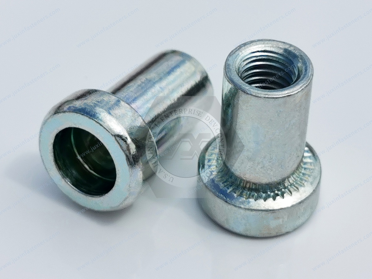
These terms should not be used interchangeably.
Pull-through generally describes a failure where the fastener or its head/flange passes through or damages the surrounding sheet interface.
Pull-out may describe the rivet nut or its formed mechanical engagement being pulled from the parent material.
The two mechanisms involve different parts of the joint.
This distinction is particularly useful when investigating elevator panel failures because increasing the rivet nut's internal thread strength may not solve a parent-sheet pull-through problem.
Elevator assemblies may require resistance to rotation during screw installation and service.
Several body geometries can be considered.
External knurling increases mechanical interaction between the rivet nut and hole.
A partially hexagonal body can provide additional geometric resistance to rotation when paired with an appropriate hole.
A full hexagonal body can provide a stronger geometric anti-rotation interface when the parent panel and hole are designed accordingly.
The correct configuration depends on the assembly.
Knurled rivet nuts can be considered for applications requiring additional resistance to rotational movement.
They are particularly relevant to:
Sheet-metal panels.
Equipment brackets.
Interior structures.
Enclosures.
Serviceable components.
However, knurling does not independently guarantee zero rotation.
The final result depends on the relationship between:
Knurl geometry.
Hole diameter.
Parent material.
Sheet thickness.
Installation process.
Assembly torque.
Semi-hex and hex body designs can be useful when the application requires enhanced anti-rotation characteristics.
The hole must be designed to match the selected geometry.
If the hole is oversized or improperly formed, the geometric engagement can be reduced.
Therefore, an anti-rotation rivet nut should always be evaluated together with its mating hole.
This is one of the most important engineering considerations for elevator rivet nuts.
The hole is not simply a manufacturing detail.
It determines how the body enters the panel and how the anti-rotation geometry interacts with the parent material.
Relevant variables include:
Hole diameter.
Hole shape.
Hole tolerance.
Burr condition.
Panel thickness.
Surface coating.
Hole location.
Distance from panel edges.
A rivet nut specification should therefore define the required installation hole according to the selected product design.
Grip range is the range of parent-material thickness for which a specific rivet nut configuration is intended to form its mechanical lock correctly.
Elevator structures can involve:
Single sheet.
Double-sheet overlap.
Formed panels.
Brackets attached to panels.
Coated sheet.
Laminated decorative structures.
The effective grip should be calculated from the actual assembly stack.
Do not select the rivet nut solely because its nominal length appears suitable.
Stainless steel is widely used in visible elevator interiors because of its appearance, durability, and architectural appeal.
Thin stainless panels can create specific fastening challenges.
The engineer may need to consider:
Limited thread engagement for direct tapping.
Visible surface quality.
Local deformation.
Hole quality.
Surface scratching.
Corrosion behavior.
Galvanic compatibility.
Repeated service assembly.
A mechanically installed threaded insert can be useful where welding or direct tapping is unsuitable.
Visible elevator surfaces can have brushed, satin, polished, or other architectural finishes.
Fastening processes should avoid unnecessary damage to the visible surface.
Blind rivet nut installation itself does not introduce welding heat.
However, installation tooling, fixtures, chips, burrs, incorrect hole preparation, or excessive local loading can still affect the finished panel.
Production teams should therefore control the complete installation process.
The original attraction of blind rivet nuts in some elevator panel applications is that they provide a mechanical fastening method without a welding operation at the installation point.
This can help avoid welding-related:
Heat input.
Local distortion.
Weld discoloration.
Post-weld surface finishing.
Weld spatter.
This does not mean every elevator assembly should replace welded connections with rivet nuts.
The two processes have different structural and manufacturing characteristics.
The correct selection depends on the load, accessibility, production process, appearance, and design requirements.
Stainless steel elevator components are often selected for appearance as well as function.
Welding and subsequent surface treatment can create visible discoloration or localized surface-condition changes if the process is not properly controlled.
Blind rivet nut installation avoids heat input at the fastening installation stage.
However, it would be technically incorrect to claim that blind rivet nuts alone "eliminate corrosion" or "prevent yellow water."
Stainless steel corrosion behavior depends on the alloy, surface condition, environment, contamination, fabrication process, and maintenance.
Potential material choices include:
Carbon steel.
Stainless steel.
Aluminum.
Other application-specific materials.
The correct choice depends on:
Parent material.
Environmental exposure.
Required mechanical behavior.
Appearance.
Corrosion considerations.
Mating screw material.
Cost.
Customer specification.
For visible stainless steel elevator panels, stainless steel rivet nuts may be considered where material compatibility and appearance are important.
Stainless steel rivet nuts may be considered for applications requiring corrosion resistance or compatibility with stainless sheet.
Common stainless configurations include austenitic stainless grades such as 304 or 316, subject to the actual customer specification and application environment.
The specific material should be confirmed against the customer's drawing or purchasing specification.
A generic statement that "stainless steel is suitable for all elevator environments" would be inappropriate.
Carbon steel rivet nuts can be considered for concealed or general-purpose elevator equipment assemblies where the application requirements permit.
Surface treatment may be used to improve corrosion resistance.
The finish should be selected according to:
Indoor or outdoor environment.
Humidity.
Chemical exposure.
Appearance requirements.
Contact with other metals.
Customer specifications.
Aluminum rivet nuts can be considered where weight reduction is a design priority.
Potential applications include:
Lightweight equipment structures.
Aluminum panels.
Interior assemblies.
Transportation-related equipment.
Specialized elevator components.
Because aluminum has different mechanical and corrosion behavior from steel, the complete joint should be evaluated before material substitution.
Material compatibility becomes important when different metals are joined.
For example, an aluminum panel combined with a stainless or carbon-steel rivet nut may require evaluation depending on moisture exposure and the surrounding environment.
Potential design controls include:
Compatible material selection.
Appropriate surface treatment.
Electrical isolation.
Sealants or barrier layers.
Environmental control.
The rivet nut should therefore be selected as part of the complete material system.
Closed-end rivet nuts may be considered for equipment enclosures or assemblies where a closed-end insert is preferred.
Potential applications include:
Control boxes.
Equipment enclosures.
Protected electrical assemblies.
Enclosed elevator equipment.
A closed-end rivet nut should not automatically be described as waterproof.
If a specific environmental or IP protection requirement exists, the complete assembly must be evaluated and tested according to the applicable requirement.
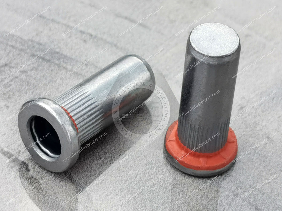
These terms should also be distinguished.
A closed-end rivet nut has a closed distal end.
A sealing rivet nut incorporates a sealing feature intended to reduce fluid or contamination ingress around the fastening interface.
A closed-end design does not automatically provide the same sealing function.
For elevator applications exposed to outdoor conditions or wash-down environments, the complete enclosure and fastening interface should be evaluated.
The original product concept identifies M6 and M8 as common elevator fastening sizes.
They can certainly be relevant in many industrial assemblies.
However, engineers should not standardize every elevator panel connection on M6 or M8 without evaluating the joint.
Thread selection depends on:
Applied load.
Available space.
Screw size.
Thread engagement.
Panel design.
Bracket geometry.
Installation access.
Required service cycles.
Customer specification.
M4, M5, M6, M8 and other thread sizes can all be appropriate for different applications.
An M8 rivet nut is not automatically the correct choice simply because it has a larger thread than M6.
Joint performance can be limited by:
Parent sheet.
Hole.
Rivet nut body.
Installation quality.
Mating screw.
Local panel geometry.
This is especially important in thin architectural panels where the sheet may be the limiting component.
The rivet nut and mating screw should be evaluated together.
Important considerations include:
Thread compatibility.
Screw material.
Screw strength.
Surface treatment.
Assembly torque.
Corrosion compatibility.
Required removal cycles.
For stainless steel elevator panels, the material and surface condition of the mating screw can also influence the practical assembly experience.
A rivet nut can rotate during screw installation if the applied torque exceeds the rotational resistance provided by the installed interface.
Potential contributors include:
Oversized hole.
Insufficient anti-rotation geometry.
Weak parent material.
Incorrect grip.
Improper installation.
Excessive assembly torque.
The solution is not automatically a stronger thread.
The engineer should identify whether the failure occurs at the thread, the insert-to-panel interface, or the panel itself.
The installation tool must deform the rivet nut correctly.
Installation stroke can influence:
Collapse geometry.
Clamping condition.
Rear-side bulb formation.
Final seating.
The appropriate setting depends on the specific rivet nut design and application.
A generic installation stroke should not be applied across unrelated rivet nut designs.
Installation force and installation stroke are related but not identical process variables.
The correct process window depends on:
Fastener material.
Body geometry.
Grip range.
Panel thickness.
Hole diameter.
Tool type.
For production applications, the installation procedure should be established around the selected fastener and actual panel condition.
Powered installation tools can be useful for repetitive elevator panel assembly.
Potential benefits include:
Reduced manual effort.
More consistent installation.
Faster repetitive assembly.
Better process repeatability when properly controlled.
However, the tool must be compatible with the selected rivet nut and production process.
Tool compatibility should be confirmed during production validation rather than assumed from the thread size.
Thin elevator panels can be sensitive to local forces.
Potential deformation can occur if:
The hole is incorrect.
The rivet nut is incorrectly sized.
Installation force is excessive.
Grip selection is wrong.
The panel lacks local support.
The correct solution may involve changing the rivet nut geometry, hole, installation parameters, or local panel design.
The location of a rivet nut relative to a panel edge can influence the behavior of the surrounding material.
A fastener installed too close to an edge may increase the risk of local deformation or tearing depending on the panel and applied load.
For engineered applications, edge distance should therefore be considered in the drawing and validation process.
Some elevator components consist of multiple sheet layers.
The supplier needs to know whether the rivet nut is installed through:
One panel.
Two overlapping sheets.
A bracket and panel.
A formed section.
A composite stack.
The total stack thickness can change the required grip range.
A reinforced head may be attractive for decorative panel applications where the designer needs a particular flange geometry.
However, the visible side of the panel may also impose requirements for:
Head diameter.
Head profile.
Seating.
Surface protection.
Clearance.
Cosmetic appearance.
A technical drawing should define these requirements explicitly.
Blind rivet nuts can be considered for attachment of:
Interior trim.
Decorative panels.
Equipment brackets.
Serviceable covers.
Interior support components.
For visible surfaces, installation tooling and panel protection should be controlled to avoid cosmetic damage.
Elevator door systems involve moving components and precise interfaces.
Blind rivet nuts may be relevant to selected brackets, covers, panels, or serviceable components.
However, a fastening component used in a critical load path or safety-related mechanism should not be approved solely because it is marketed as an elevator rivet nut.
The actual load path, applicable elevator requirements, and customer design approval must govern the selection.
Equipment enclosures and protective sheet-metal structures can require threaded mounting points.
Blind rivet nuts can provide single-sided installation for:
Covers.
Brackets.
Electrical equipment.
Cable-management hardware.
Service panels.
Material and finish should reflect the environmental conditions of the installation location.
Car-top equipment can contain brackets, covers, electrical components, and serviceable assemblies.
Where access to the rear side of a panel is limited, blind rivet nuts can provide a practical threaded mounting method.
The supplier should receive the application drawing and required load information for any engineered connection.
Pit and shaft environments can present additional exposure to:
Moisture.
Dust.
Condensation.
Cleaning chemicals.
Corrosive conditions.
For these applications, material and surface treatment should be selected according to the actual environment.
Closed-end or sealing configurations may be considered where appropriate, but they should not be treated as a substitute for complete enclosure sealing.
One of the most useful lessons when sourcing reinforced-head rivet nuts is that head thickness is only one dimensional variable.
Engineers should also consider:
Head thickness + head diameter + bearing area + panel thickness + hole diameter + parent material.
A 5 mm head dimension without these surrounding parameters does not fully describe the fastening interface.
This is why a drawing is more valuable than a product name alone when sourcing custom elevator rivet nuts.
If a rivet nut pulls through an elevator panel, simply selecting a stronger insert may not solve the problem.
The limiting component may be the panel.
The engineer should investigate:
Panel thickness.
Panel material.
Head bearing area.
Hole diameter.
Edge distance.
Applied load.
Load direction.
This approach identifies the actual failure mechanism instead of treating the rivet nut as an isolated component.
A knurled, semi-hex, or hex body does not operate independently.
The hole must support the intended body geometry.
A mismatched hole can reduce the benefit of the anti-rotation feature.
Therefore:
Rivet nut geometry + hole geometry + parent material
should be treated as one design interface.
Increasing rivet nut strength can be unnecessary if the parent sheet is the actual limiting component.
Likewise, a larger thread can increase assembly size and cost without solving a panel-deformation problem.
The correct question is:
"What joint performance is required in the actual elevator panel?"
rather than:
"What is the strongest rivet nut available?"
In elevator interiors, the visible panel may be part of the architectural finish.
Therefore, engineering requirements can include both mechanical and cosmetic characteristics.
These may include:
Flange profile.
Seating.
Surface damage prevention.
Hole quality.
Burr control.
Installation tooling.
Material compatibility.
Surface finish.
This makes elevator fastening different from many concealed industrial applications.
A serviceable elevator component may be removed multiple times during maintenance.
In such cases, the engineer should evaluate:
Thread wear.
Mating screw condition.
Assembly torque.
Removal torque.
Parent-sheet stability.
Insert retention.
Corrosion.
The expected service cycle should be considered when selecting the fastening system.
Blind rivet nuts should be specified according to the applicable product, material, dimensional, and customer requirements.
Unlike blind rivets, which have dedicated international standard series covering specific product configurations,
blind rivet nuts are frequently specified through manufacturer standards, customer drawings, dimensional specifications, and application-specific requirements.
For material selection, relevant standards may include applicable ASTM, EN, DIN, ISO, SAE, or other recognized material specifications depending on the selected material.
For stainless-steel fastener materials, applicable ISO 3506 requirements may be considered where the product and application fall within its scope.
The important principle is to identify the exact standard and scope rather than attach an unrelated standard number to a product.
For a custom elevator rivet nut, the drawing should ideally define:
Thread.
Head diameter.
Head thickness.
Overall length.
Body diameter.
Body geometry.
Grip range.
Hole requirement.
Material.
Surface treatment.
Critical tolerances.
Inspection requirements.
If the "5 mm reinforced head" is a critical feature, the drawing should clearly identify the 5 mm dimension and its tolerance.
A professional elevator rivet nut RFQ should include:
Part number.
Drawing revision.
Thread size.
Thread specification.
Head type.
Head dimensions.
Body geometry.
Grip range.
Parent-sheet thickness.
Hole diameter.
Material.
Surface treatment.
Mating screw.
Application location.
Environmental exposure.
Required inspection.
Documentation requirements.
Packaging requirements.
Prototype quantity.
Annual production volume.
This information allows suppliers to quote against the actual technical requirement rather than a generic catalog description.
Procurement and supplier-development teams should ask potential suppliers:
Can you manufacture the specified head geometry?
Can you support reinforced-head configurations?
What body geometries are available?
What grip ranges are available?
What materials are available?
What surface treatments are available?
What hole diameter is recommended?
How is thread quality controlled?
What dimensional inspection is performed?
Can production follow customer drawings?
What traceability is available?
What packaging options are available?
What engineering samples can be provided for validation?
These questions are useful when developing a long-term OEM fastening source.
Quality requirements should be based on the customer's drawing and application.
Potential inspection characteristics include:
Head thickness.
Head diameter.
Body diameter.
Overall length.
Thread dimensions.
Grip-related dimensions.
Material.
Surface treatment.
Appearance.
Critical geometric features.
Where a reinforced 5 mm head is a critical characteristic, it should be specifically identified in the inspection plan.
The internal thread is the interface with the mating screw.
Inspection may include appropriate thread gauges and dimensional verification according to the agreed specification.
Important characteristics can include:
Thread size.
Pitch.
Thread tolerance.
Thread depth.
Thread cleanliness.
Thread damage.
For OEM applications, the inspection requirement should be agreed before production.
International OEM customers may require documentation related to:
RoHS.
REACH.
Customer-specific restricted substances.
Surface-treatment requirements.
Packaging requirements.
Material declarations.
The exact documentation should be defined by the customer's purchasing and compliance requirements.
Blind rivet nuts are only one component of an elevator fastening system.
Depending on the assembly, other components may include:
Screws.
Bolts.
Washers.
Spacers.
Brackets.
Clips.
Plastic fasteners.
Machined components.
JUXIN FASTENERS also supplies related fastening solutions for industrial and automotive assemblies.
For broader structural fastening requirements, see high-strength bolts and nuts.
For conventional threaded hardware, see industrial and automotive bolts and nuts.
For precision metal components used alongside fastening systems, see stainless steel CNC machining parts.
For lightweight non-metallic mounting and cable-management applications, see automotive plastic fasteners.
A practical selection process can follow this sequence:
Step 1: Identify the elevator component.
Step 2: Identify the parent panel material.
Step 3: Confirm panel thickness.
Step 4: Confirm the hole diameter and hole geometry.
Step 5: Define the required thread.
Step 6: Determine the grip range.
Step 7: Define the required head geometry.
Step 8: Determine whether anti-rotation is required.
Step 9: Select open-end, closed-end, or sealing construction where applicable.
Step 10: Select material.
Step 11: Select surface treatment.
Step 12: Confirm mating screw compatibility.
Step 13: Define installation tooling.
Step 14: Identify service loads and environmental conditions.
Step 15: Validate the complete joint.
Step 16: Establish inspection and documentation requirements.
Step 17: Release the production RFQ.
For important elevator applications, validation should focus on the actual panel and assembly.
Depending on the application, testing may evaluate:
Installation consistency.
Pull-out behavior.
Pull-through behavior.
Torque-out behavior.
Spin-out behavior.
Parent-sheet deformation.
Mating screw compatibility.
Corrosion behavior.
Repeated assembly.
Environmental exposure.
The exact test method and acceptance criteria should be established by the customer according to the application and applicable requirements.
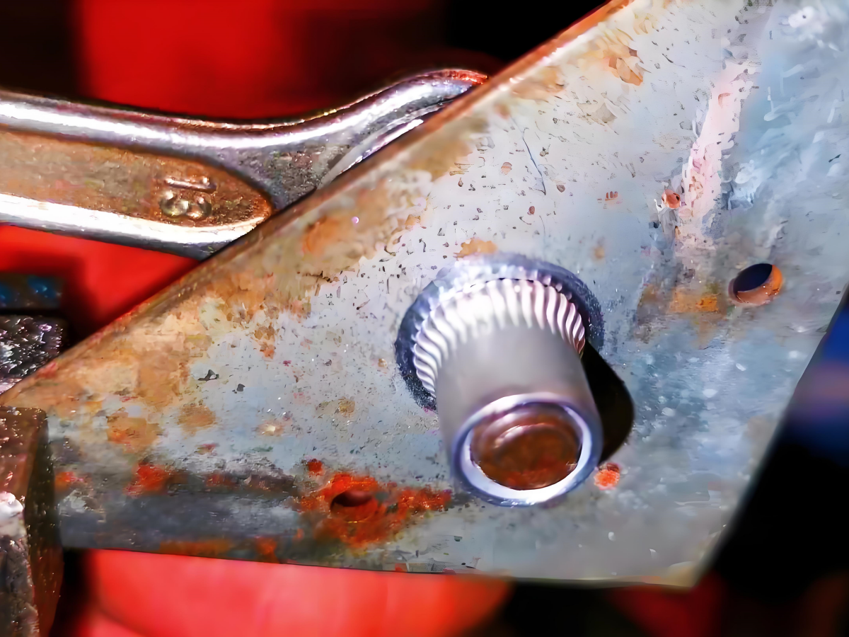
A strong OEM sourcing process connects engineering information with procurement information.
The commercial path can be:
Application → Drawing → Material → Thickness → Hole → Thread → Grip → Head → Body → Material → Finish → Validation → Quality Requirements → Quantity → RFQ → Production
This structure helps procurement teams obtain technically comparable quotations from suppliers.
For elevator manufacturing, the total cost of a fastening solution may include:
Fastener price.
Installation labor.
Tooling.
Assembly cycle time.
Rework.
Panel damage.
Scrap.
Packaging.
Logistics.
Inventory.
Field service.
A slightly different rivet nut geometry may therefore have a meaningful effect on total assembly cost if it improves installation consistency or reduces panel damage.
Procurement teams should communicate:
Prototype quantity.
Pilot quantity.
Monthly demand.
Annual demand.
Forecast.
Packaging requirements.
Delivery location.
Required documentation.
Engineering-change expectations.
This information allows the supplier to evaluate the commercial requirements of the program more accurately.
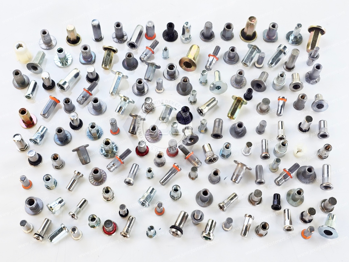
JUXIN FASTENERS supplies blind rivet nut solutions for industrial OEM applications where single-sided threaded fastening is required.
Potential configurations can include:
Reinforced-head blind rivet nuts.
Flat-head blind rivet nuts.
Knurled rivet nuts.
Semi-hex rivet nuts.
Hex-body rivet nuts.
Open-end rivet nuts.
Closed-end configurations.
Sealing configurations.
Stainless steel rivet nuts.
Carbon steel rivet nuts.
Aluminum rivet nuts.
Custom rivet nut dimensions.
The final configuration should be selected according to the customer's drawing, panel, application, environment, and production requirements.
A product name such as "5 mm reinforced elevator rivet nut" does not contain enough information for reliable OEM sourcing.
The supplier needs to know what the 5 mm dimension represents and how it relates to the complete geometry.
A controlled drawing can eliminate ambiguity around:
Head thickness.
Head diameter.
Body diameter.
Thread.
Grip.
Hole.
Material.
Finish.
This is especially important when multiple suppliers are being evaluated.
For design engineers, a practical specification should begin with the joint.
Ask:
What component is being attached?
What is the parent material?
What is the panel thickness?
What is the hole diameter?
What thread is required?
What grip range is required?
Is anti-rotation necessary?
Is a reinforced head required?
What does the 5 mm dimension refer to?
Is the surface visible?
What material and finish are required?
What mating screw will be used?
What service loads exist?
Is repeated assembly expected?
What environmental exposure exists?
This produces a much more useful engineering specification than simply requesting an "elevator rivet nut."
For procurement, supplier comparison should include both commercial and technical criteria.
Compare:
Exact drawing compliance.
Material.
Head geometry.
Grip range.
Hole requirement.
Thread quality.
Surface treatment.
Inspection.
Documentation.
Packaging.
Production quantity.
Supply capability.
Change-control requirements.
The objective is to ensure that quotations are technically equivalent before comparing unit price.
"5 mm head," "heavy head," "reinforced head," and "elevator rivet nut" can mean different things between suppliers.
Procurement teams should therefore avoid sourcing purely by product title.
The controlled drawing should remain the technical reference.
This is one of the simplest ways to prevent apparently interchangeable rivet nuts from becoming non-interchangeable during production.
If the application has a pull-through problem, evaluate head geometry and parent sheet.
If the problem is spin-out, evaluate body geometry, hole, parent material, and installation.
If the problem is pull-out, evaluate the formed mechanical lock and panel.
If the problem is corrosion, evaluate the complete material and surface-treatment system.
If the problem is cosmetic damage, evaluate installation tooling and panel protection.
Different problems require different engineering solutions.
An elevator panel may be mechanically functional and architecturally visible at the same time.
That means a fastening solution can have two simultaneous requirements:
Mechanical: retention, installation, load, serviceability.
Architectural: seating, surface protection, appearance, corrosion behavior.
A product that satisfies only the mechanical requirement may still be unsuitable for a visible interior panel.
A heavier or stronger fastener can increase material cost, weight, installation force, or panel loading without solving the actual design problem.
The appropriate selection balances:
Required joint performance.
Parent-sheet capability.
Installation process.
Weight.
Cost.
Corrosion.
Appearance.
Serviceability.
This system-level approach is particularly important in elevator manufacturing.
Before sending an RFQ, prepare:
Product
Blind rivet nut.
Reinforced head requirement.
Open or closed end.
Anti-rotation geometry.
Dimensions
Thread.
Head thickness.
Head diameter.
Body diameter.
Overall length.
Grip range.
Assembly
Panel thickness.
Panel material.
Hole diameter.
Hole shape.
Edge distance where relevant.
Mating screw.
Environment
Indoor/outdoor.
Humidity.
Cleaning chemicals.
Corrosion exposure.
Visible architectural surface.
Commercial
Prototype quantity.
Annual quantity.
Packaging.
Delivery location.
Documentation.
Inspection requirements.
If you are developing elevator car panels, door-related assemblies, equipment enclosures, architectural sheet-metal components, control boxes, or other elevator equipment requiring single-sided threaded fastening, send JUXIN FASTENERS the relevant drawing and application information.
For the fastest technical evaluation, provide:
2D drawing.
3D model where available.
Thread size.
Head dimensions.
Panel material.
Panel thickness.
Hole diameter.
Grip range.
Anti-rotation requirement.
Open or closed-end requirement.
Material.
Surface treatment.
Mating screw.
Application environment.
Annual quantity.
Direct OEM Engineering & Procurement Contact:
info@juxinfasteners.com
JUXIN FASTENERS can evaluate the specified elevator blind rivet nut requirements based on the customer's drawing, application, technical specification, and sourcing requirements.
 MORE NEWS

Sep. 25, 2026

Sep. 25, 2026

Sep. 25, 2026
Contact Us
Tel.:
+86 020 8621 0320
+86 020 3121 6067
E-mail:
Technical Support:
Navigation
SEND INQUIREY