
Call Us
+86 136 6007 9809
Call Us
+86 136 6007 9809

Apr. 18, 2023
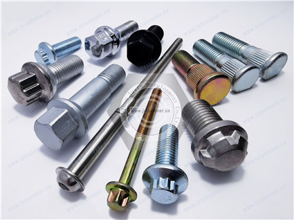
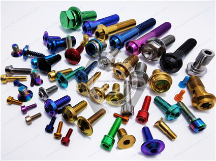
Modern automotive engineering requires two seemingly opposite objectives: high structural integrity at the wheel-end and continuous weight reduction throughout the vehicle body and chassis.
Wheel-end fasteners must maintain reliable clamping force under cyclic tension, lateral loading, braking loads, vibration, thermal cycling, and repeated service operations.
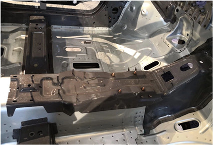
At the same time, the increasing use of aluminum alloys, extrusions, castings, and mixed-material structures in Body-in-White (BIW) and vehicle body systems has created demand for joining technologies that can work without conventional welding or extensive pre-machining.
 |  |
This makes automotive fastener selection more than a simple decision between a bolt and a nut.
The engineer must consider:
Fastener material and mechanical property class
Thread size and tolerance
Wheel seat geometry
Bearing surface design
Clamp load and tightening torque
Joint stiffness
Fatigue and vibration environment
Corrosion protection
Hydrogen embrittlement risk for high-strength plated steel
Assembly accessibility
Sheet thickness and material stack-up
Aluminum alloy formability
Single-sided versus two-sided assembly access
Tooling requirements
Serviceability and removability
Automated assembly requirements
PPAP and traceability requirements
This engineering guide brings these considerations together into one framework covering both automotive wheel fasteners and lightweight aluminum body joining technologies.
The guide focuses on four major areas:
 |  |
Wheel-End Fastener Mechanics: Engineering distinctions between wheel bolts, press-in wheel studs, and lug nuts across different vehicle architectures.
Wheel Seat Geometry: Technical differences between tapered/conical, spherical/ball, and flat/mag seat designs and why matching the wheel and fastener interface is critical.
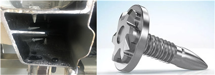
Lightweight Aluminum BIW Joining: Comparison of Flow Drill Screws (FDS), Self-Piercing Rivets (SPR), compression riveting, clinching, and other mechanical joining approaches.
Strategic Procurement: How automotive purchasing teams can specify materials, mechanical properties, coatings, geometry, assembly requirements, inspection, and documentation before releasing an RFQ.
For international automotive sourcing, it is also important to distinguish between a published international standard, a regional standard, an OEM drawing requirement, and a supplier-specific process specification. Not every automotive fastener technology has a single ISO standard defining the complete finished product.
 |  |
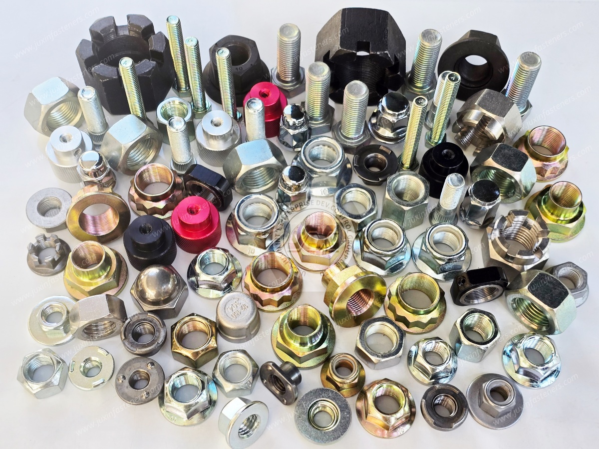
Automotive wheel bolts, wheel studs, and lug nuts operate in highly dynamic environments.
The applicable standard depends on the fastener type, thread system, geometry, material, and customer specification.
For carbon and alloy steel externally threaded fasteners, ISO 898-1:2013 remains the relevant published ISO property-class standard,
while ISO is currently developing its replacement edition. ISO 898-1 covers bolts, screws, and studs made from carbon or alloy steel and defines mechanical and physical properties for specified property classes.
For steel nuts, ISO 898-2:2022 is the current ISO standard covering mechanical and physical properties for specified property classes.
The older ISO 898-6 references should not be used as the current general nut standard because those older editions have been withdrawn.
| Fastener Category | Applicable Standard / Reference | Typical Material / Grade Direction | Key Engineering Considerations | Typical Automotive Application |
|---|---|---|---|---|
| High-Tensile Wheel Bolts | ISO 898-1 property classes where applicable; SAE J1199 for applicable metric automotive fasteners | Alloy steel / boron steel / medium-carbon alloy steel | Tensile strength, proof/yield behavior, fatigue design, thread quality, head-to-shank transition, seat geometry | Wheel-end assemblies, hub-to-wheel attachment systems |
| Automotive Lug Nuts | ISO 898-2:2022 where applicable; SAE J995 for applicable inch-series automotive steel nuts | Medium-carbon or alloy steel | Proof load, hardness, thread quality, seat design, prevailing torque if specified | Wheel stud and lug nut systems |
| Wheel Studs | ISO 898-1 where the stud geometry and application fall within its scope; OEM drawing/specification may add requirements | Medium-carbon alloy steel / boron steel | Tensile strength, fatigue, knurl geometry, press-in retention, hub compatibility | Press-in wheel stud systems |
| Aluminum Arc-Welded Studs | ISO 13918:2017 for applicable arc-welded studs and ceramic ferrules | Application-specific aluminum alloy | Stud material, weldability, base-material compatibility, weld energy, mechanical performance | Grounding points, brackets, harness and fluid-line mounting |
| Flow Drill Screws (FDS) | Supplier/OEM/process specification; FDS is a joining technology rather than a generic DIN 7500 or ISO 14583 product category | Case-hardened alloy steel or application-specific steel | Tip geometry, thread-forming capability, hardness profile, drive system, coating, sheet stack-up | Aluminum and steel BIW, closed sections, extrusions |
| Self-Piercing Rivets (SPR) | OEM/joining-system specification and supplier process qualification | Application-specific ductile rivet steel | Rivet hardness/ductility, stack-up, die geometry, penetration and interlock | Aluminum BIW, mixed-material structures |
| Zinc-Flake-Coated High-Strength Fasteners | ISO 10683:2018 | High-strength carbon/alloy steel | Corrosion resistance, coating thickness/system, friction behavior, hydrogen embrittlement risk | Chassis and automotive structural fasteners |
ISO 898-1 does not by itself define every performance characteristic required for an automotive wheel bolt.
The standard explicitly does not establish requirements for properties such as fatigue resistance, weldability, corrosion resistance, or complete torque/clamp-force performance.
Those characteristics may need additional testing, OEM specifications, drawing requirements, or application validation.
Likewise, ISO 898-2:2022 covers specified property classes for carbon and alloy steel nuts, but a specialized wheel nut geometry, coating system, prevailing-torque feature, seat design,
or OEM application may require additional specifications.
For non-electrolytically applied zinc-flake coatings on steel fasteners, ISO 10683:2018 is particularly relevant to high-strength fasteners.
The standard specifically addresses zinc-flake coating systems and notes their use for high-strength fasteners to reduce the risk associated with internal hydrogen embrittlement.
Modern vehicle wheel-end architectures generally use one of two major fastening philosophies:
              WHEEL-END MOUNTING ARCHITECTURE COMPARISON

      WHEEL BOLT SYSTEM                         WHEEL STUD + LUG NUT SYSTEM
   ┌─────────────────────────┐                ┌─────────────────────────┐
   │      Wheel / Rotor      │                │      Wheel / Rotor      │
   │          │              │                │          │              │
   │     Wheel Bolt          │                │      Lug Nut            │
   │     ┌───────┐           │                │     ┌───────┐           │
   │─────┤ Head  ├──────     │                │─────┤ Nut   ├──────     │
   │     └───┬───┘           │                │         │                │
   │         │               │                │    Threaded Stud         │
   │         │               │                │══════════════════        │
   │   Threaded Hub Hole     │                │     Press-Fit Knurl       │
   │══════════════════       │                │─────────┬────────         │
   │       Hub / Flange      │                │     Hub / Flange          │
   └─────────────────────────┘                └─────────────────────────┘
A wheel bolt incorporates an integrated head and external thread. The bolt passes through the wheel and threads directly into a tapped hole in the wheel hub or hub flange.
The final design may include a specialized bearing or seat geometry between the bolt head and wheel.
Engineering characteristics:
Direct threading into the hub
No permanent wheel stud protruding from the hub
Wheel bolt head provides the clamping interface
Hub thread must withstand repeated installation and removal
Seat geometry must match the wheel design
Thread engagement and hub material must be evaluated together
Assembly torque and friction condition directly influence clamp load
Common application context:
Wheel-bolt architectures are widely associated with many European vehicle platforms, although the actual fastening architecture is determined by the individual OEM platform rather than by a simple geographic rule.
Engineering advantages:
No permanent stud protrusion
Compact hub-side architecture
Potential packaging advantages
Straightforward wheel removal once the bolts are removed
Suitable for automated torque-controlled assembly
A critical design consideration is that the wheel bolt and tapped hub form a joint system.
Increasing bolt strength does not automatically solve a weak hub thread, insufficient engagement, poor seat matching, or excessive friction variation.
A wheel stud is permanently or semi-permanently retained in the wheel hub or flange. The wheel is positioned over the protruding studs and secured with lug nuts.
Press-in wheel studs commonly use a serrated or knurled section beneath the head to create mechanical interference with the hub flange.
Engineering characteristics:
Permanent or semi-permanent stud retention
Knurled or serrated press-fit section
External thread above the hub
Separate lug nut provides final clamping force
Wheel is guided onto the studs during assembly
Stud-to-hub retention must resist installation and service loads
Engineering advantages:
Easier wheel positioning during service
Reduced need to hold and align a loose bolt during initial installation
Positive guidance of the wheel through the protruding studs
Suitable for high-volume service and assembly environments
Stud and nut can be optimized as separate components
The key engineering point is that press-in wheel stud retention is not the same as threaded joint strength. The designer must evaluate:
Knurl diameter
Knurl form
Hub hole diameter
Interference
Hub flange thickness
Material hardness
Installation force
Rotation resistance
Pull-out resistance
Fatigue behavior
Service removal conditions
The interface between the wheel fastener and the wheel mounting hole is one of the most important elements in a wheel fastening system.
The fastener may be mechanically strong enough while the joint is still unsuitable if the seat geometry does not match the wheel.
Typical seat families include:
+----------------------------------------------------------------------------------+
|                         WHEEL SEAT GEOMETRY                                     |
+-----------------------------+-----------------------------+----------------------+
| CONICAL / TAPERED SEAT      | SPHERICAL / BALL SEAT       | FLAT / MAG SEAT      |
|                             |                             |                      |
|          \     /            |        _________            |      _________       |
|           \   /             |      /           \          |     |  WASHER |      |
|            \ /              |     (   RADIUS    )         |     |_________|      |
|             V               |      \___________/          |         │             |
|                             |                             |       FLAT            |
+-----------------------------+-----------------------------+----------------------+
A conical wheel seat uses an angled contact surface between the fastener and wheel.
A 60° seat is common in many automotive and aftermarket wheel applications, but the actual required angle must always match the wheel manufacturer's specification.
Engineering behavior:
Creates a radial wedging component
Provides centering behavior
Transfers load through the defined bearing surface
Influences friction and clamp-load repeatability
Requires precise geometric compatibility
The important point is not simply whether the fastener is “60°.”
The seat angle, contact diameter, bearing width, and wheel-hole geometry must be treated as one interface system.
Using a 60° lug nut or wheel bolt on a wheel designed for a spherical seat is not a valid substitution simply because the nominal thread size is identical.
A spherical or ball seat uses a curved bearing surface that mates with a corresponding wheel pocket.
Common designations may include specific spherical radii, but the exact radius must be matched to the wheel design rather than assumed from the vehicle brand.
Engineering characteristics:
Curved bearing interface
Reduced dependence on a sharp conical contact line
Defined load transfer through the spherical interface
Requires correct radius matching
Common in various European and OEM wheel designs
A flat-seat or mag-style wheel fastener uses a flat bearing surface, often with a washer or captive washer arrangement.
The washer increases the effective bearing area between the fastener and wheel.
Engineering characteristics:
Flat axial bearing interface
Larger bearing area can be useful with suitable wheel designs
Captive washer may control the bearing interface
Helps manage contact stresses on softer wheel materials
Requires correct shank length and wheel-hole geometry
The washer does not automatically make the joint safer. The designer must still verify:
Washer diameter
Washer thickness
Shank length
Wheel-hole depth
Thread engagement
Wheel thickness
Contact pressure
Installation torque
Service clearance
A wheel fastener is ultimately part of a preloaded bolted joint.
The objective of tightening is not simply to achieve a particular torque value.
The actual engineering objective is to generate and maintain the required clamp force while staying within the mechanical limits of the fastener and joint.
A simplified torque relationship can be represented as:
[
T \approx K \cdot F \cdot d
]
Where:
(T) = tightening torque
(K) = torque coefficient influenced by friction
(F) = desired preload / clamp force
(d) = nominal fastener diameter
This relationship is intentionally simplified.
In real automotive assemblies, friction varies with:
Thread condition
Coating
Lubrication
Seat geometry
Washer condition
Surface finish
Installation speed
Temperature
Contamination
Reuse history
Therefore, a torque specification should not be treated as a universal value that can be transferred between different fastener coatings or seat designs.
For engineering validation, torque/clamp-force testing can be evaluated using appropriate test methods such as ISO 16047 where applicable.
Consider two wheel bolts with the same:
M12 thread
Grade
Nominal torque
If one has a dry zinc-flake coating and the other has a different friction-controlled coating, the resulting clamp force distribution may differ significantly.
Therefore, procurement specifications should define the complete friction condition, not only the nominal tightening torque.
For production programs, this may include:
Coating system
Lubricant or topcoat
Coefficient-of-friction target
Torque window
Clamp-force window
Assembly speed
Tool calibration
Torque-angle strategy where applicable
Test method
The increased use of aluminum sheet, aluminum extrusions, cast aluminum nodes, and mixed-material structures has changed automotive joining requirements.
Traditional resistance spot welding remains important for many steel structures, but mechanical joining becomes especially attractive when:
Different materials must be joined
Heat input should be minimized
Aluminum alloys are sensitive to thermal effects
Access is available from only one side
Closed sections or hollow profiles must be assembled
Serviceability or removability is required
Automated joining must be integrated into robotic production
A simplified selection matrix is:
                  ALUMINUM BIW JOINING DECISION PATH

     Single-Sided Access Required?
                    │
              ┌─────┴─────┐
             YES           NO
              │             │
              ▼             ▼
       FLOW DRILL SCREW     Multi-layer sheet?
          (FDS)             │
                            ├──────── YES ───────► SPR
                            │
                            ▼
                    High-load anchor?
                            │
                            ├──────── YES ───────► Compression /
                            │                       structural rivet
                            │
                            ▼
                       Bracket / stud?
                            │
                            └──────────────► Aluminum Stud Welding
Compression riveting creates a mechanical joint by plastically deforming a rivet or fastener through the material stack.
Depending on the system, the joining mechanism may involve:
Radial expansion
Undercut formation
Flange deformation
Mechanical interlock
Local material displacement
Potential applications include:
Aluminum chassis structures
Stamped sheet assemblies
Extrusion-to-sheet joints
Cast-to-sheet connections
Structural mounting points
The actual load capacity depends heavily on:
Sheet thickness
Material grade
Hole condition
Rivet geometry
Rivet material
Tool force
Die geometry
Edge distance
Stack-up
Blind riveting uses a mandrel-driven sleeve or rivet body that can be installed from one accessible side.
The process is useful when the rear side of the joint cannot be reached.
Potential applications include:
Enclosures
Body panels
Brackets
Thin-wall structures
Serviceable assemblies
Multi-layer sheet stacks
However, conventional blind rivets and structural blind rivets should not be treated as interchangeable. Structural applications require evaluation of:
Shear strength
Tensile strength
Mandrel retention
Hole filling
Joint stiffness
Fatigue
Corrosion protection
Self-Piercing Riveting is a mechanical joining process in which a semi-tubular rivet penetrates the upper material layer and
forms an interlock inside the lower material without requiring a conventional pre-drilled through-hole.
A simplified process is:
      SPR INSTALLATION

      Rivet
        │
        ▼
       \ /
        V
  ───────────────  Top Sheet
       \   /
        \ /
  ─────────────────  Bottom Sheet
       \___/
        ↑
   Mechanical Interlock
During installation:
The rivet is driven into the sheet stack.
The rivet pierces the upper layer.
The rivet expands within the lower layer.
The anvil controls the final deformation.
A mechanical interlock is created.
No conventional pre-drilling
Suitable for automated production
Useful for multi-layer sheet stacks
Can join selected dissimilar materials
No conventional fusion-welding heat-affected zone
Compatible with robotic manufacturing
High repeatability when the stack-up and tooling are controlled
SPR is particularly useful where both sides of the joint are accessible because the rivet and anvil operate as a forming system.
The most important difference is accessibility and joint architecture.
SPR generally requires controlled access for the joining head and anvil.
FDS is specifically valuable when only one side is accessible.
Therefore:
Open two-sided sheet stack → SPR may be highly suitable.
Closed hollow section → FDS may provide a major assembly advantage.
This distinction is often more useful to an engineer than simply comparing the nominal tensile strength of the two fasteners.
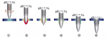
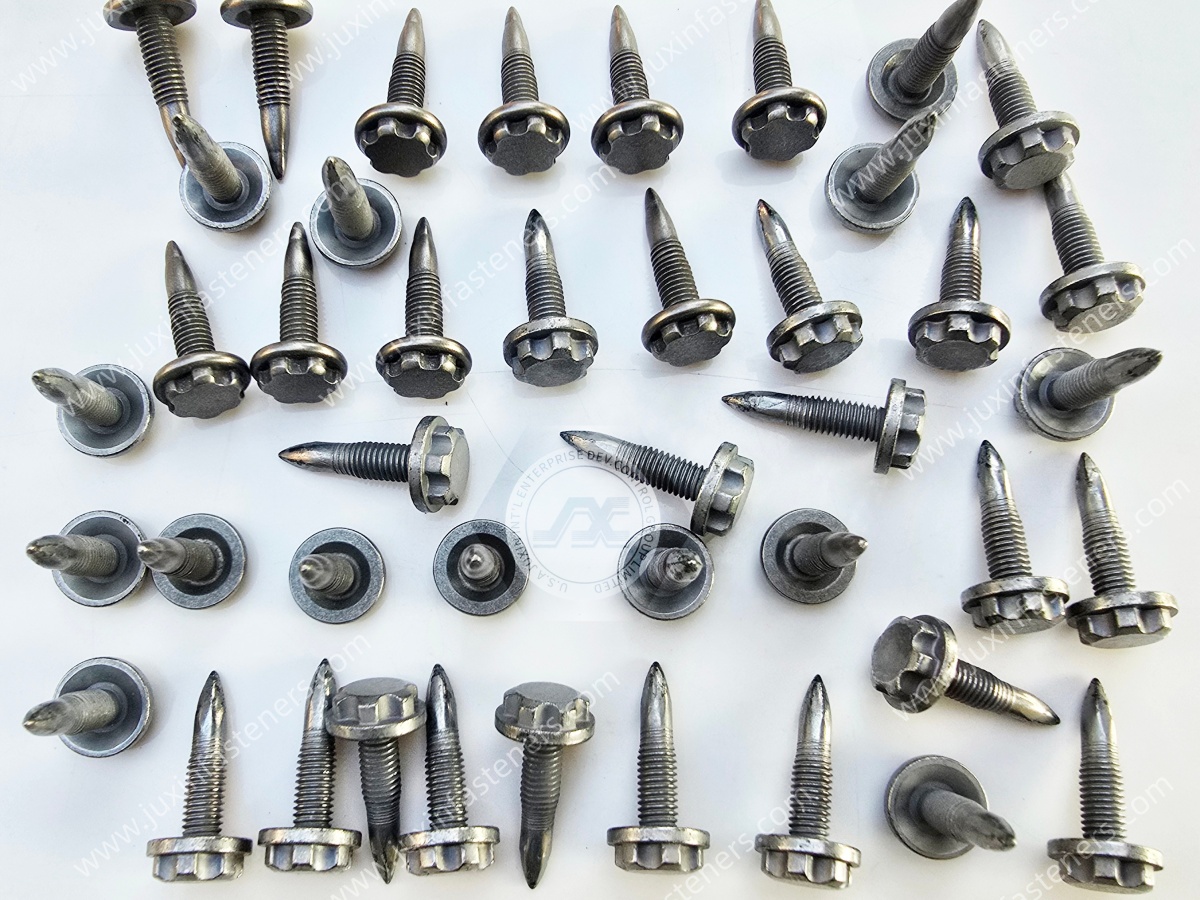
Flow Drill Screws are specialized screws designed to create a joint in sheet or extrusion material by using rotational speed and axial force to locally heat and plastically form the material.
FDS systems are widely associated with automotive lightweight construction because they can create detachable joints in aluminum and steel sheet structures with one-sided access.
Commercial FDS systems are engineered as complete fastener-and-tooling solutions rather than as ordinary tapping screws.
A typical installation sequence is:
      FDS INSTALLATION SEQUENCE

  1. CONTACT             2. FLOW / PIERCING

        ↓                        ↓
      ─────                  ────────
       /\/\                  \  ↑  /
      /    \                  \ │ /
     Sheet                  Formed Sleeve


  3. THREAD FORMATION       4. FINAL JOINT

        ↓                         ↓
     ────────                 ────────
       ╲   ╱                 ──╲___/──
        ╲_╱                     │
        Thread                FDS Screw
       Formation              Installed
Depending on the system and application, the screw can form an extrusion or sleeve in the sheet and generate increased thread engagement.
One-sided installation
No conventional pre-drilling in suitable applications
No separate nut required
No conventional chips from tapping
Removable joint
Suitable for closed profiles
Compatible with automated screwdriving
Useful for aluminum and steel sheet structures
Potentially improved serviceability and recyclability
FDS manufacturers provide application-specific design recommendations because installation parameters depend on the sheet material, thickness, stack-up, screw geometry, tooling, and required joint performance.
This is one of the strongest engineering reasons to select FDS.
Consider an aluminum longitudinal beam with a closed cross-section.
An SPR system requires an anvil behind the material.
If the rear side of the joint is physically inaccessible, SPR cannot simply be substituted without changing the structure or tooling.
An FDS system can approach the joint from the accessible side and form the joint using the screw itself.
Therefore:
Closed section + one-sided access + detachable joint → FDS becomes a strong candidate.
A simplified screw-joint relationship can be expressed conceptually as:
[
F_{\text{clamping}} \approx
\frac{T_{\text{drive}}}
{\left(
\frac{P}{2\pi}
+
\mu_t r_t
+
\mu_b r_b
\right)}
]
Where:
(F_{\text{clamping}}) = approximate generated clamp force
(T_{\text{drive}}) = applied installation torque
(P) = thread pitch
(\mu_t) = effective thread friction coefficient
(r_t) = effective thread friction radius
(\mu_b) = bearing/friction coefficient
(r_b) = effective bearing radius
This is a simplified engineering relationship rather than a universal FDS design equation.
Actual FDS joint performance depends on the interaction between:
Screw geometry
Thread formation
Formed sleeve dimensions
Sheet thickness
Material strength
Friction
Drive speed
Axial force
Final torque
Joint relaxation
Environmental conditions
Arc stud welding can be used to create mounting points directly on aluminum structures.
ISO 13918:2017 specifies requirements for studs and ceramic ferrules used in arc stud welding, including dimensions, materials, and mechanical properties.
For aluminum applications, however, the final joint must be engineered around the specific:
Stud alloy
Base-metal alloy
Sheet thickness
Surface condition
Welding process
Weld energy
Stud diameter
Stud geometry
Electrical parameters
Mechanical load
Corrosion environment
Potential applications include:
Grounding points
Cable and harness brackets
Fluid-line supports
Sensor mounting
Electrical component brackets
Lightweight body structures
The material should therefore be specified by exact alloy and application requirement rather than simply stating “AlMg3” or “AlMg5” as a universal solution.
This decision matrix helps engineering and procurement teams select the joining technology according to joint function rather than simply purchasing the lowest-cost fastener.
| Joint Category | Primary Fastener / Joining Choice | Critical Selection Criteria | Key Procurement Risk / Trade-Off | Target Role |
|---|---|---|---|---|
| Wheel-End Rotational Assembly | High-Tensile Wheel Bolts / Wheel Studs + Lug Nuts | Mechanical property class, seat geometry, thread engagement, fatigue requirements, coating/friction condition | Incorrect seat geometry, friction variation, coating-related embrittlement risk, inadequate clamp load | Chassis Design / Purchasing Manager |
| Press-In Wheel Stud Assembly | Knurled / Serrated Wheel Stud | Knurl geometry, hub-hole tolerance, interference, pull-out and rotation resistance | Hub damage during installation, inadequate retention, excessive insertion force | Wheel-End Engineer / Supplier Quality |
| Wheel Stud + Lug Nut System | Automotive Lug Nut | Property class where applicable, thread fit, seat geometry, prevailing torque, coating | Wrong seat type or friction condition can alter clamp load | Chassis / Procurement |
| Closed Box-Section BIW Joinery | Flow Drill Screws (FDS) | Single-sided access, formed sleeve, thread engagement, screw hardness, drive profile | Tool wear, incorrect speed/force profile, unsuitable sheet stack-up | BIW Manufacturing / Sourcing Specialist |
| Multi-Material Sheet Stackups | Self-Piercing Rivets (SPR) | Rivet ductility/hardness, sheet stack-up, die geometry, interlock | Tooling alignment, stack-up variation, higher initial equipment investment | Structural Engineer / Supply Chain Lead |
| Heavy Chassis Mounting Points | Structural / Compression Rivet Fasteners | Push-out, pull-out, shear, sheet thickness, flange geometry | Dedicated tooling and application-specific validation | Design Engineer / Strategic Sourcing |
| Aluminum Bracket Mounting | Arc-Welded Aluminum Studs | Alloy compatibility, weld process, stud dimensions, base material | Weld quality and heat/process sensitivity | Manufacturing Engineer |
| Accessible Lightweight Sheet Joint | Mechanical Rivet / Structural Blind Rivet | Joint thickness, shear/tensile loads, serviceability, corrosion protection | Wrong rivet type can produce insufficient structural performance | Body Engineer / Procurement |
For automotive wheel fasteners, a purchasing specification should contain substantially more information than:
“M12 wheel bolt, grade 10.9.”
A production RFQ should ideally define:
Product type: wheel bolt / wheel stud / lug nut
Thread diameter
Thread pitch
Thread length
Overall length
Head diameter
Head height
Drive style
Seat type
Seat angle or radius
Bearing diameter
Washer requirement
Shank length
Knurl diameter for press-in studs
Knurl length
Knurl profile
Material grade
Property class
Tensile strength
Yield/proof requirements
Hardness
Fatigue requirement where specified
Torque/clamp-force requirement
Installation torque
Reuse requirement
Service-temperature range
Coating type
Coating thickness
Topcoat
Lubrication/friction modifier
Corrosion requirement
Hydrogen embrittlement controls where applicable
For high-strength steel fasteners, non-electrolytically applied zinc-flake coating systems can be considered where the corrosion system and friction requirements are appropriate.
ISO 10683:2018 specifically covers such coating systems for steel fasteners and highlights their relevance to high-strength fasteners.
Material certificate
Mechanical test report
Dimensional inspection report
Coating certificate
Torque/clamp-force data where required
Lot traceability
PPAP documentation where required
Control plan
Process flow
Inspection plan
Packaging specification
Certificate of conformity
A robust automotive wheel fastener program should evaluate the complete joint rather than focusing only on ultimate tensile strength.
Possible causes:
Incorrect torque
Excessive friction
Low friction
Coating variation
Incorrect seat geometry
Surface contamination
Washer variation
Possible causes:
Excessive cyclic stress
Insufficient preload
Stress concentration
Poor head-to-shank transition
Surface defects
Thread root geometry
Installation damage
Possible causes:
Cross-threading
Insufficient engagement
Contaminated threads
Excessive torque
Repeated service cycles
Hub material incompatibility
Possible causes:
Incorrect conical angle
Incorrect spherical radius
Incorrect flat-seat configuration
Excessive local bearing pressure
Improper washer geometry
Soft wheel material
High-strength steel fasteners can require special consideration when electroplated.
The coating system, baking/process controls, material hardness, and quality system should therefore be specified together.
For applicable high-strength fasteners, ISO 10683:2018 provides a relevant non-electrolytic zinc-flake coating framework specifically addressing this type of application.
| Requirement | FDS | SPR | Compression / Structural Riveting | Aluminum Stud Welding |
|---|---|---|---|---|
| One-sided access | Excellent | Limited | Depends on system | Generally accessible from welding side |
| Closed profile | Excellent | Difficult / generally unsuitable | Application dependent | Application dependent |
| Removable joint | Excellent | Generally no | Usually no | No |
| Pre-drilling | Often unnecessary in suitable FDS systems | No conventional pre-drilling | Depends on system | No conventional hole required |
| Automated production | Excellent | Excellent | Excellent with dedicated tooling | Excellent with controlled welding |
| Aluminum joining | Yes | Yes | Yes | Yes |
| Mixed-material joining | Yes, application dependent | Yes, application dependent | Yes, application dependent | Limited by weld compatibility |
| Rework/serviceability | High | Low | Low to medium | Low |
| Tooling dependence | Medium | High | High | Medium to high |
| Main design variable | Screw + formed sleeve | Rivet + die + stack-up | Rivet + tooling + stack-up | Stud + weld process |
The table should be treated as an engineering screening tool rather than a substitute for application validation.
For automotive sourcing teams, the most important procurement question is not:
“Which fastener has the highest tensile strength?”
The better question is:
“Which fastening system provides the required joint performance with the lowest total manufacturing and lifecycle risk?”
A procurement team should therefore evaluate five layers:
Define whether the joint requires:
Wheel clamping
Structural load transfer
Shear resistance
Pull-out resistance
Vibration resistance
Grounding
Bracket mounting
Serviceability
Sealing
Define:
Steel
Aluminum
Stainless steel
Mixed materials
Sheet thickness
Extrusion geometry
Casting interface
Define:
One-sided access
Two-sided access
Robot installation
Manual assembly
Press installation
Screwdriving
Riveting
Stud welding
Define:
Zinc plating
Zinc-nickel
Zinc-flake
Organic topcoat
Lubrication
Friction coefficient
Galvanic compatibility
Environmental exposure
Define:
Material certification
Dimensional inspection
Mechanical testing
Coating verification
Torque/clamp-force testing
PPAP
Traceability
Process capability
Packaging
Change control
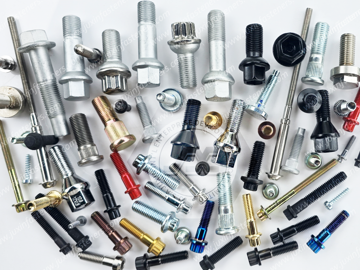
Expand your understanding of automotive and industrial fastening technology through the following JUXIN FASTENERS technical resources:
Bolt Exposed Thread Length Standards & High-Vibration Lock Nuts
https://www.juxinfasteners.com/technical-guide/bolt-exposed-thread-length-anti-loosening-fasteners/
Covers thread engagement, bolt-end protrusion, high-vibration locking strategies, and all-metal lock nut selection.
Specialized Nut Engineering Guide: Cap Nuts, Wing Nuts & Titanium Flange Nuts
https://www.juxinfasteners.com/industrial-solutions/cap-nuts-wing-nuts-titanium-flange-nuts-engineering-guide/
Covers specialized nut geometries, application-specific material selection, and weight-critical fastening.
Threaded Inserts for Plastics: Engineering Installation Guide
https://www.juxinfasteners.com/industrial-solutions/thread-insert-nuts-engineering-installation-guide/
Covers threaded inserts for plastics, heat-set inserts, post-molding installation, polymer boss design, and insert retention.
Precision Knurled Brass Threaded Inserts Guide
https://www.juxinfasteners.com/industrial-solutions/knurled-brass-inserts-after-molding-installation-guide/
Covers knurled brass inserts, heat staking, ultrasonic insertion, plastic boss design, pull-out resistance, and rotational retention.
Automotive Fasteners & Hardware Parts
https://www.juxinfasteners.com/products/automotive-fasteners-hardwares-parts/
Explore automotive fasteners, hardware components, and application-specific manufacturing solutions.
Weld Fasteners
https://www.juxinfasteners.com/products/weld-fasteners/
Related solutions for weld studs, weld nuts, and mounting points used in automotive and sheet-metal assemblies.
A common mistake in fastener sourcing is to select the component independently from the assembly.
For example:
M12 + Class 10.9 + high tensile strength
does not automatically mean the wheel joint is correctly engineered.
The complete system includes:
Wheel + seat + fastener + hub + thread + coating + friction + torque + preload + service environment
Likewise, for aluminum BIW:
FDS vs. SPR
should not be decided only by nominal fastener strength.
The engineer must first ask:
Is the joint accessible from one side?
Is the profile open or closed?
Is the joint permanent or removable?
What is the material stack-up?
Are aluminum and steel being joined?
What is the required shear and pull-out performance?
What production equipment is available?
What cycle time is required?
What level of serviceability is required?
What corrosion environment will the joint experience?
This joint-first approach prevents the common procurement error of selecting a technically strong fastener that is incompatible with the actual assembly process.
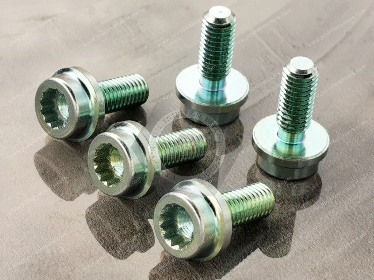
JUXIN FASTENERS supports OEM and industrial sourcing programs requiring custom automotive fasteners and precision hardware.
Depending on product requirements, manufacturing processes may include:
Cold heading
Multi-station cold forming
CNC turning
CNC machining
Thread rolling
Knurling
Stamping
Precision forming
Heat treatment
Surface treatment
Optical sorting
Dimensional inspection
Thread inspection
Mechanical testing
Application-specific validation
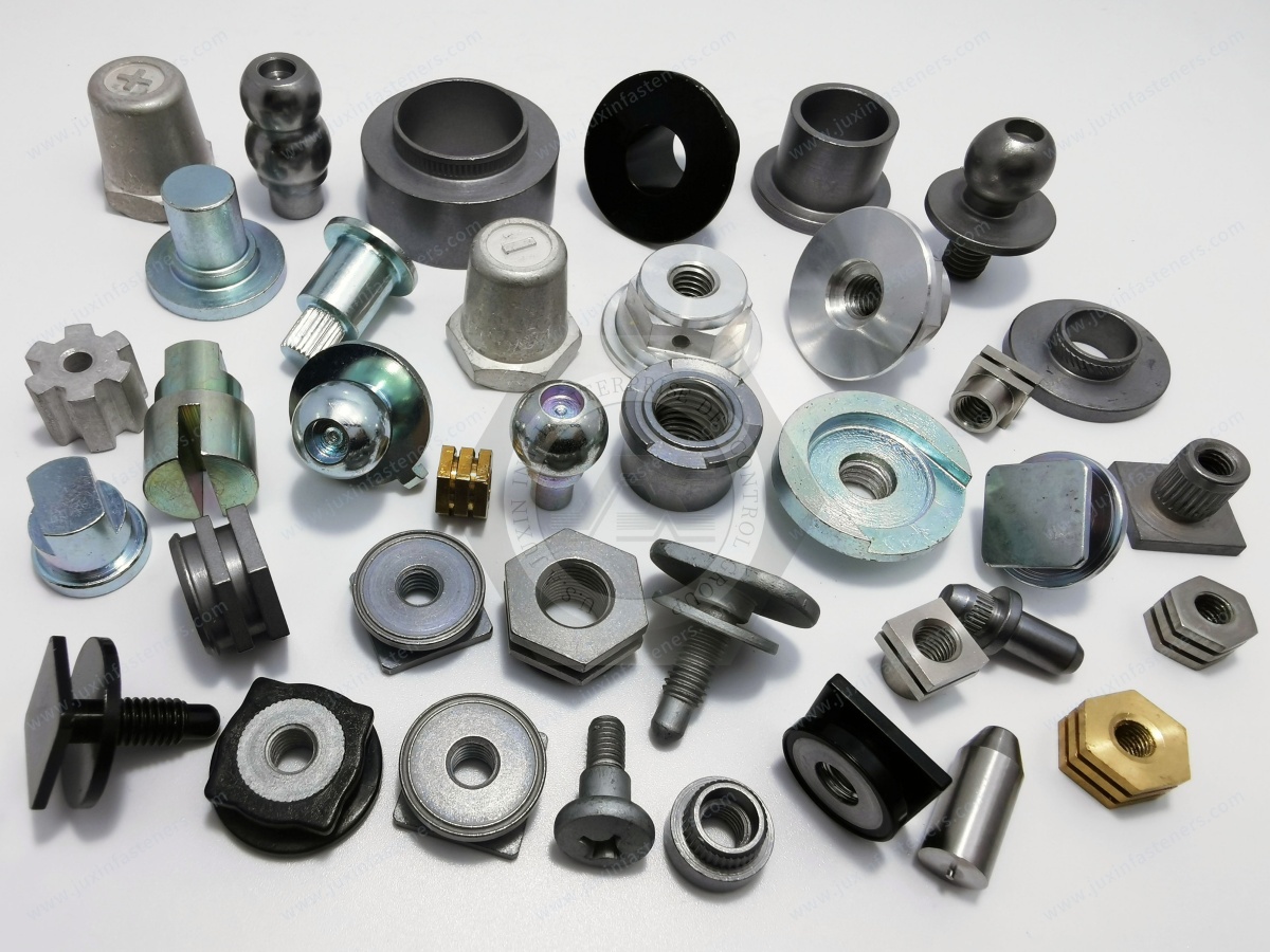
JUXIN FASTENERS can support development specifications for:
Wheel bolts
Wheel studs
Lug nuts
High-strength automotive bolts
Custom flange bolts
Knurled studs
Press-fit studs
Special seat geometry fasteners
Custom automotive hardware
Depending on the application and production requirement, sourcing discussions can also include:
Flow Drill Screw-type components
Structural riveting components
Weld studs
Aluminum mounting studs
Custom cold-formed fasteners
CNC-machined automotive hardware
For specialized FDS or SPR programs, the final fastener geometry, material, coating, installation tooling, and process parameters should be validated against the actual customer material stack-up and production equipment.
When requesting a quotation for automotive wheel fasteners or aluminum body fasteners, provide as much of the following information as possible:
Product Type
Wheel bolt
Wheel stud
Lug nut
FDS screw
SPR rivet
Compression rivet
Weld stud
Custom automotive fastener
Dimensions
Diameter
Pitch
Length
Head dimensions
Seat angle/radius
Bearing diameter
Shank length
Knurl dimensions
Rivet dimensions
Material
Carbon steel
Alloy steel
Boron steel
Stainless steel
Aluminum alloy
Other specified alloy
Mechanical Requirement
Property class
Tensile strength
Proof load
Hardness
Shear strength
Pull-out requirement
Rotation resistance
Fatigue requirement
Surface Treatment
Zinc plating
Zinc-nickel
Zinc-flake
Organic coating
Passivation
Lubrication
Friction coefficient requirement
Assembly Requirement
Installation torque
Clamp force
Torque-angle
Press-in force
Pull-out force
Drive speed
Tooling
One-sided/two-sided access
Quality Requirement
PPAP
Material certificate
Inspection report
Coating report
Mechanical test report
Traceability
Packaging specification
Certificate of conformity
Automotive wheel fasteners and lightweight aluminum joining systems operate at very different points in the vehicle architecture, but they share the same fundamental engineering principle:
The fastener must be designed as part of the joint, not as an isolated component.
For wheel-end systems, reliable performance depends on the interaction between:
Fastener Grade + Thread + Seat Geometry + Hub + Friction + Torque + Clamp Load + Fatigue + Corrosion
For lightweight aluminum BIW structures, performance depends on:
Material Stack-Up + Access + Joining Process + Fastener Geometry + Tooling + Interlock / Thread Formation + Corrosion + Serviceability
This is why automotive procurement should specify the complete application rather than simply requesting a generic “high-strength automotive fastener.”
For engineers and sourcing managers, the correct decision path is:
Define the joint → define the load → define the material → define the access → select the joining technology → define the fastener → validate the process → document the production specification.
JUXIN FASTENERS provides custom automotive fastening solutions for OEM, Tier-1, industrial, and specialized engineering applications, including wheel bolts, wheel studs, lug nuts, automotive hardware, custom cold-formed fasteners, weld fasteners, and precision-machined components.
Engineering & Sourcing Contact:
info@juxinfasteners.com
Official Website:
https://www.juxinfasteners.com
Automotive Fastener Capabilities:
Wheel Bolts & Wheel Studs, Lug Nuts, Automotive Fasteners, Weld Studs, Weld Nuts, Custom Cold-Formed Hardware, Precision CNC Components, and application-specific fastening solutions.
Previous: Why do Fastening Bolts Loosen?
Next: Features of knurled nuts
 MORE NEWS

Sep. 25, 2026

Sep. 25, 2026

Sep. 25, 2026
Contact Us
Tel.:
+86 020 8621 0320
+86 020 3121 6067
E-mail:
Technical Support:
Navigation
SEND INQUIREY