
Call Us
+86 136 6007 9809
Call Us
+86 136 6007 9809

Apr. 18, 2023
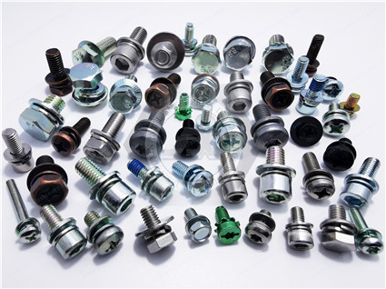
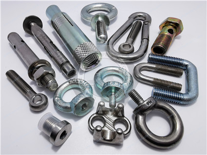
Fastener loosening and subsequent fatigue failure represent two of the most important reliability risks in bolted joints used in automotive systems,
heavy machinery, rail equipment, energy infrastructure, industrial equipment, and other dynamically loaded assemblies.
A bolted joint is designed to generate and maintain an initial preload. That preload creates the clamping force required to keep the assembled components together.
During service, however, a joint may experience:
Transverse vibration
Cyclic tensile loading
Bending loads
Shock and impact
Thermal expansion and contraction
Surface embedding
Local plastic deformation
Creep or relaxation of softer materials
Coating and friction variation
Repeated assembly and disassembly
The critical engineering issue is therefore not simply whether a bolt has a high tensile strength.
The real question is:
 |  |
Can the complete bolted joint maintain sufficient preload and control cyclic bolt stress throughout its service life?
When preload is reduced sufficiently, the joint can become more susceptible to transverse slip, separation, local bearing, bending,
and increased cyclic stress in the fastener. Under severe conditions, this can contribute to fatigue crack initiation and eventual fracture.
This technical guide provides structural engineers, procurement managers, supplier quality teams, and sourcing directors with an engineering framework covering:
Loosening Mechanics: Differentiating between rotational loosening caused by transverse movement and relative thread motion,
and non-rotational preload loss caused by embedding, material relaxation, creep, or thermal effects.
Fatigue Fracture Prevention: Explaining the relationship between preload, joint stiffness, external cyclic loading, friction variation, joint separation, and bolt stress amplitude.
Engineered Joint Optimization: Applying appropriate bolt geometry, joint elasticity, locking methods, surface treatments, coatings, and controlled assembly processes.
Testing & Validation: Understanding the roles of transverse vibration testing, torque/clamp-force testing, fatigue testing, and application-specific validation.
Strategic Procurement: Translating the engineering requirements into an RFQ specification that controls material, mechanical properties, friction, coating, locking function, inspection, and traceability.
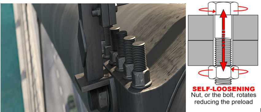
Mitigating bolt loosening and fatigue requires a distinction between fastener product standards, mechanical property standards, joint-design guidelines, coating standards, and test methods.
| Standard / Specification | Governing Body / Focus Area | Technical Objective & Criteria | Industrial Application Relevance |
|---|---|---|---|
| DIN 65151 / Junker-Type Transverse Vibration Testing | German engineering / fastener testing practice | Evaluates self-loosening behavior of bolted joints under controlled transverse displacement and cyclic loading | Automotive, railway, heavy equipment, machinery and vibration-sensitive assemblies |
| VDI 2230 | Verein Deutscher Ingenieure | Systematic calculation and evaluation of highly stressed bolted joints, including preload, joint stiffness, external loading, separation and strength | Automotive, machinery, power equipment and other highly loaded bolted joints |
| ISO 898-1 | International Organization for Standardization | Mechanical and physical properties of specified carbon/alloy steel bolts, screws and studs | High-strength metric fasteners |
| ISO 898-2:2022 | International Organization for Standardization | Mechanical and physical properties of specified carbon/alloy steel nuts and property classes | Metric steel nuts used with bolts, screws and studs |
| SAE J429 | SAE International | Mechanical and material requirements for applicable inch-series carbon and alloy steel externally threaded fasteners | Automotive, machinery and North American industrial applications |
| ISO 16047 | International Organization for Standardization | Torque/clamp-force testing and determination of friction-related assembly behavior | Torque-tension validation, coating development and automated assembly |
| ISO 10683:2018 | International Organization for Standardization | Requirements for non-electrolytically applied zinc-flake coating systems for steel fasteners | High-strength fasteners requiring corrosion protection and controlled coating systems |
| ISO 15330 | International Organization for Standardization | Preloading test for detection of hydrogen embrittlement under specified conditions | High-strength fastener quality assurance |
| ISO 16228 | International Organization for Standardization | Types of inspection documents for fasteners | Automotive and industrial supplier quality documentation |
 |  |
ISO 898-1:2013 defines mechanical and physical properties for applicable carbon-steel and alloy-steel bolts,
screws and studs, but it does not by itself define fatigue resistance, corrosion resistance, weldability, or complete torque/clamp-force performance.
Those characteristics require additional specifications or testing where applicable.
ISO 898-2:2022 is the current ISO standard for specified property classes of carbon-steel and alloy-steel nuts.
Older references such as ISO 898-6 should not be presented as the current general nut property standard.
VDI 2230 should be understood as an engineering calculation methodology/guideline for highly stressed bolted joints, rather than a product certification standard.
ISO 16047 provides a standardized framework for torque/clamp-force testing and is useful for evaluating friction and torque-tension behavior.
ISO 10683:2018 covers non-electrolytically applied zinc-flake coating systems for steel fasteners.
The standard specifically notes the use of such coatings for high-strength fasteners in relation to internal hydrogen embrittlement risk.
Preload degradation does not have a single mechanism.
Correctly identifying the failure mechanism is the first step toward selecting the appropriate anti-loosening solution.
                    FASTENER PRELOAD DECAY MECHANISMS

                                      │
                    ┌─────────────────┴─────────────────┐
                    │                                   │
                    ▼                                   ▼

          ROTATIONAL LOOSENING                 NON-ROTATIONAL PRELOAD LOSS

          • Transverse vibration               • Surface embedding
          • Joint transverse slip              • Local plastic deformation
          • Relative thread motion             • Material relaxation
          • Nut / bolt rotation                • Creep
          • Progressive preload loss           • Thermal expansion mismatch
                                               • Coating / interface settlement

                    │                                   │
                    ▼                                   ▼

          Possible Countermeasures:             Possible Countermeasures:

          • Prevailing torque nuts             • Increase joint elasticity
          • All-metal lock nuts                 • Optimize clamp length
          • Wedge-locking systems               • Reduce settlement
          • Thread-locking compounds            • Improve surface condition
          • Controlled friction                 • Optimize material pairing
Rotational loosening occurs when transverse movement of the joint produces relative displacement between the mating surfaces and threads.
This phenomenon is particularly important when the transverse load is sufficient to generate local slip across the joint interface.
The basic sequence is:
Transverse Load
      ↓
Joint Micro-Slip
      ↓
Reduction of Frictional Restraint
      ↓
Relative Thread Movement
      ↓
Progressive Nut / Bolt Rotation
      ↓
Preload Loss
      ↓
Joint Separation or Increased Dynamic Loading
The Junker transverse vibration test is widely used to investigate the self-loosening tendency of bolted joints under controlled transverse displacement.
Many engineers initially associate bolt loosening primarily with axial vibration.
However, a bolted joint can be particularly vulnerable when the external load produces transverse movement between the clamped components.
Once the interface slips sufficiently, the friction that normally restrains relative movement is reduced.
This is why a bolt that appears completely secure under static inspection can progressively lose preload under dynamic transverse loading.
Important variables include:
Initial preload
Transverse displacement amplitude
Joint stiffness
Surface friction
Thread friction
Bearing friction
Fastener geometry
Joint thickness
External load magnitude
Load frequency
Locking mechanism
Surface finish
Coating
Temperature
Rather than relying on a single universal equation for all threaded joints, engineers should use established joint-design methods and application-specific vibration testing to validate the actual configuration.
Non-rotational preload loss occurs when the bolt or nut does not visibly rotate, but the elastic deformation in the joint decreases.
This can occur through:
When a fastener is tightened, high local contact stresses exist at:
Thread flanks
Bearing surfaces
Washer interfaces
Coated surfaces
Rough machined surfaces
Joint interfaces
Microscopic surface peaks can deform or flatten.
The resulting change in joint thickness may reduce bolt elongation and therefore reduce preload.
The effect is strongly dependent on:
Surface roughness
Material hardness
Contact pressure
Joint geometry
Number of interfaces
Fastener size
Initial preload
Joint stiffness
Therefore, a specific statement such as “10 μm settlement always causes 20–50% preload loss” should not be treated as a universal engineering rule.
When a steel bolt clamps an aluminum housing, for example, the aluminum and steel have different coefficients of thermal expansion.
The approximate differential thermal expansion can be expressed as:
(\alpha_{\text{joint}}-\alpha_{\text{bolt}})
L\Delta T
]
Where:
(\alpha_{\text{joint}}) = effective thermal expansion coefficient of the clamped material
(\alpha_{\text{bolt}}) = thermal expansion coefficient of the bolt
(L) = relevant joint length
(\Delta T) = temperature change
Depending on joint geometry and temperature range, the differential expansion can increase or reduce bolt preload.
At elevated temperatures, additional mechanisms may occur:
Material creep
Stress relaxation
Loss of hardness
Coating changes
Interface deformation
Thermal cycling fatigue
This is why high-temperature joints should not be evaluated only at room temperature.
A fractured bolt does not necessarily mean the bolt was simply overloaded beyond its ultimate tensile strength.
Fatigue failure can occur when a fastener experiences repeated cyclic stress over a large number of load cycles.
A common failure sequence is:
                  FATIGUE FRACTURE FAILURE SEQUENCE       [1] Initial Preload Is Too Low
                       │
                       ▼       [2] Preload Decays During Service
                       │
                       ▼       [3] Joint Interface Begins to Slip
                       │
                       ▼       [4] Joint Separation / Load Redistribution
                       │
                       ▼       [5] Bolt Receives Higher Cyclic Stress
                       │
                       ▼       [6] Local Stress Concentration
           at Thread Root / Fillet
                       │
                       ▼       [7] Fatigue Crack Initiation
                       │
                       ▼       [8] Progressive Crack Growth
                       │
                       ▼       [9] Final Fracture
It is not technically reliable to state that a fixed percentage of industrial field failures are caused by insufficient preload.
Actual fatigue failure can result from multiple interacting causes, including:
Excessive external load
Insufficient preload
Joint separation
Stress concentration
Incorrect bolt geometry
Manufacturing defects
Thread damage
Corrosion
Hydrogen embrittlement
Bending
Poor alignment
Surface defects
Improper tightening
Fatigue-sensitive joint design
Therefore, failure analysis should identify the actual fracture morphology and load history rather than assigning a universal percentage to one cause.
In a friction-type bolted joint, the clamping force generates friction at the interfaces.
A simplified expression is:
[
F_{\text{slip resistance}}
\approx
\mu_{\text{interface}}
\sum F_v
]
Where:
(F_{\text{slip resistance}}) = approximate resistance to interface slip
(\mu_{\text{interface}}) = coefficient of friction at the joint interface
(F_v) = bolt preload
(\sum F_v) = combined clamping force across the relevant interfaces
If the actual preload is substantially below the design requirement, the available frictional resistance is reduced.
The joint may then experience:
High Preload
     ↓
High Interface Friction
     ↓
Limited Slip
     ↓
Bolt Mainly Carries Axial Load

VERSUS

Low Preload
     ↓
Reduced Interface Friction
     ↓
Joint Slip
     ↓
Hole / Shank Contact
     ↓
Additional Bending + Shear
     ↓
Higher Fatigue Risk
This does not mean every slipped joint immediately fractures.
The actual result depends on:
Hole clearance
Bolt diameter
Joint geometry
Load direction
Bolt bending stiffness
Material strength
Number of cycles
Joint alignment
Contact conditions
The fatigue behavior of a bolted joint is strongly influenced by the cyclic stress range experienced by the fastener.
A simplified relationship can be written as:
\frac{\Delta F_b}{2A_s}
]
Where:
(\sigma_a) = alternating stress amplitude in the bolt
(\Delta F_b) = bolt force range
(A_s) = tensile stress area
The bolt force range is influenced by the relationship between bolt stiffness and clamped-part stiffness.
A simplified joint-force relationship is:
\Phi_k \Delta F_A
]
Where:
(\Delta F_b) = cyclic bolt load range
(\Delta F_A) = external load range
(\Phi_k) = joint force ratio
For a properly designed elastic joint, only a portion of the external load variation may be transferred into the bolt.
The exact value of (\Phi_k) depends on the actual stiffness relationship and joint geometry. It should therefore be calculated rather than assumed to always be 0.10–0.20.
An important engineering distinction is:
Higher preload increases mean bolt stress but can reduce the bolt's cyclic load variation when the joint remains properly clamped.
This is why a properly designed preloaded joint can provide better fatigue performance than a lightly tightened joint, even though the bolt begins operation at a higher mean stress.
The engineering objective is therefore not:
“Use the lowest possible preload.”
Nor is it:
“Use the highest possible preload.”
The objective is:
“Select an appropriate preload window that maintains joint integrity without exceeding the fastener or joint limits.”
To control both rotational loosening and non-rotational preload loss, JUXIN FASTENERS can support the selection of fastening architectures based on the actual joint environment.
+--------------------------------------------------------------------------------+
|                     JUXIN FASTENERS ANTI-LOOSENING MATRIX                     |
+--------------------------------+--------------------------------+--------------+
| ALL-METAL LOCK NUTS            | HIGH-ELASTICITY / WAISTED BOLTS | THREAD LOCKING|
|                                |                                | SYSTEMS       |
| • Prevailing torque            | • Increased elastic length    | • Chemical    |
| • No nylon insert              | • Lower bolt spring rate      |   thread lock |
| • Useful at elevated temp.     | • Better settlement tolerance | • Seals /     |
| • Suitable for vibration       | • Reduced cyclic bolt load   |   secures     |
|                                |   under suitable conditions   |   threads     |
+--------------------------------+--------------------------------+--------------+
A longer effective clamping length can increase the elastic deformation capacity of the joint.
A simple geometric indicator is:
[
\frac{L_k}{d}
]
Where:
(L_k) = effective clamping length
(d) = nominal bolt diameter
A larger (L_k/d) ratio can improve tolerance to small amounts of settlement because the same dimensional loss represents a smaller proportion of the total elastic elongation.
However, there is no universal rule that every joint should use:
[
L_k/d \ge 5
]
The optimum ratio depends on:
Joint stiffness
Bolt stiffness
Available installation space
External load
Temperature
Material
Required preload
Fatigue requirement
A waisted or reduced-shank bolt can be designed to increase the elastic length of the fastener.
A reduced shank can:
Lower axial spring stiffness
Increase elastic deformation
Reduce the proportion of external load transferred into the bolt under suitable joint conditions
Improve tolerance to settlement
Potentially improve fatigue performance
The exact shank diameter must be calculated based on:
Required tensile strength
Fatigue strength
Manufacturing capability
Stress concentration
Thread transition
Minimum cross-sectional area
The original concept of reducing the shank to approximately (0.8 \times d_2) should therefore be treated as a design example rather than a universal dimensional rule.
Thread and bearing friction have a major influence on the torque-to-preload relationship.
For a simplified torque relationship:
[
T \approx KFd
]
Where:
(T) = tightening torque
(K) = combined torque coefficient
(F) = preload
(d) = nominal diameter
The coefficient (K) is not a material constant.
It changes with:
Thread friction
Bearing friction
Coating
Lubrication
Surface finish
Installation speed
Temperature
Contact pressure
Therefore, specifying only:
“Torque = 100 N·m”
may be insufficient for a high-performance production joint.
The procurement specification should also control the friction condition.
For high-strength steel fasteners, non-electrolytically applied zinc-flake coating systems are an important option where corrosion protection,
friction control, and hydrogen-embrittlement risk management must be considered together.
ISO 10683:2018 covers zinc-flake coating systems for steel fasteners, including configurations with topcoats and lubricants.
A coating specification should define, where applicable:
Coating system
Topcoat
Lubricant
Friction coefficient
Corrosion requirement
Application process
Coating thickness
Thread condition
Rather than claiming that every zinc-flake coating must operate at one universal friction range such as (\mu = 0.10–0.16),
the actual target should be defined by the selected coating system and validated through torque/clamp-force testing.
All-metal prevailing-torque nuts are commonly considered when:
Nylon inserts are unsuitable
Temperature is elevated
Vibration is significant
Repeated service is expected
Chemical exposure exists
A deformed-thread or prevailing-torque feature creates additional resistance to rotation.
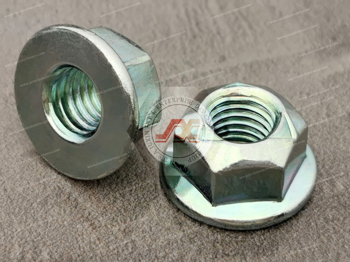
DIN 980V is associated with all-metal prevailing-torque hexagon nuts.
However, the nut itself should not be marketed simply as having an unlimited “extreme temperature” capability.
The actual service temperature depends on:
Nut material
Heat treatment
Thread deformation
Coating
Lubrication
Mating bolt
Assembly temperature
Required prevailing torque
Service environment
For high-temperature joints, the complete fastener system should be validated at the intended service temperature.
Wedge-locking washers use the difference between:
Cam angle
Thread helix angle
to resist loosening under vibration.
The basic mechanism is:
Bolt / Nut
    │
    ▼
Washer Pair
 ┌─────────┐
 │  CAM    │
 │  /\ /\  │
 │ /  V  \ │
 └─────────┘
    │
    ▼
Clamped Joint
When the bolt or nut attempts to rotate, the washer pair must climb the cam surfaces.
The resulting wedging action can increase resistance to rotational loosening.
The suitability of wedge-locking washers depends on:
Joint geometry
Bearing surface
Available space
Washer hardness
Coating
Preload
External vibration
Surface condition
They should not automatically be assumed to outperform every other locking system in every application.
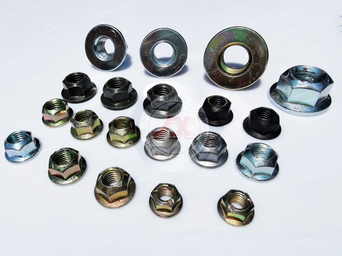
Thread-locking compounds can provide additional resistance to relative thread movement.
Micro-encapsulated thread-locking systems can be applied during fastener production so that the locking agent is integrated into the thread interface.
Potential benefits include:
Controlled application
No separate dispensing operation at final assembly
Thread sealing
Increased resistance to vibration
Consistent application volume
Reduced assembly process steps
However, chemical locking should be specified according to:
Temperature range
Cure condition
Chemical compatibility
Breakaway torque
Prevailing torque
Reusability
Storage life
Assembly time
The locking compound should be considered part of the joint system, not simply an accessory added after the mechanical design is complete.
Selecting an anti-loosening and fatigue-resistant fastener depends on operational temperature, vibration, cyclic loading, assembly method, environmental exposure, and service requirements.
| Industry Sector | Primary Failure Risk | Recommended Fastener Architecture | Standards / Engineering References | Strategic Sourcing Focus |
|---|---|---|---|---|
| Heavy Construction & Mining | Impact shock, transverse vibration, cyclic loading | All-Metal Lock Nuts + High-Strength Bolts | ISO 898-1, ISO 898-2, applicable DIN nut standards, vibration validation | Lot traceability, coating system, prevailing torque, corrosion resistance, impact/fatigue validation |
| Automotive Powertrain & Chassis | Cyclic thermal loading, vibration, joint relaxation, fatigue | High-Strength Bolts + Locking / Friction-Controlled Fastener Systems | VDI 2230, ISO 16047, ISO 898-1 / 898-2, OEM specification | Torque-tension capability, automated feeding, friction consistency, PPAP, traceability |
| Wind Energy & Turbines | High cyclic loading, flange movement, fatigue | High-Strength Bolts / Studs with application-specific locking strategy | VDI 2230 or applicable engineering calculation, ISO 898-1 where applicable, project/OEM specification | Fatigue validation, preload monitoring, coating, NDT where specified, lot traceability |
| Process Piping & Pressure Vessels | Thermal cycling, relaxation, high-temperature exposure | ASTM A193 B7 Studs + ASTM A194 Nuts where specified by the design code | ASME B31.3, ASME B16.5, ASTM A193/A194 and project specification | MTRs, hardness, material traceability, high-temperature suitability, dimensional control |
| Rail Transportation | Long-term vibration, cyclic loading, maintenance cycles | High-strength bolts + application-specific locking system | EN/ISO/OEM/project-specific requirements | Vibration testing, fatigue performance, corrosion protection, maintenance strategy |
| Industrial Machinery | Gear vibration, shock, cyclic loads | High-strength bolts + prevailing torque or other engineered locking solution | ISO 898, VDI 2230, ISO 16047 as applicable | Torque consistency, automated assembly, serviceability, coating/friction |
| Agricultural Equipment | Shock, dirt, vibration and outdoor corrosion | High-strength bolts + prevailing torque nuts | Application-specific ISO/SAE/DIN requirements | Corrosion resistance, serviceability, locking performance, bulk supply |
A coating claim such as:
“1000+ hours salt spray”
should not be inserted into a general product specification unless the exact coating system, test method, substrate, thickness, pretreatment, test conditions, and acceptance criteria are defined.
Similarly, “zero hydrogen embrittlement” is too absolute as a generic procurement statement.
A better RFQ requirement is:
“Hydrogen embrittlement risk shall be controlled according to the specified material, hardness, coating process, baking/process controls, and applicable validation requirements.”
When a customer reports a loose or fractured bolt, replacing the fastener with a stronger grade should not automatically be the first action.
The investigation should begin with the joint.
Determine:
Original tightening method
Torque specification
Torque tool calibration
Torque scatter
Lubrication condition
Coating condition
Assembly operator/process
Torque-angle information if available
Check:
Joint surface condition
Washer condition
Embedding
Surface damage
Hole clearance
Alignment
Joint thickness
Material deformation
Check:
Thread damage
Thread galling
Head-to-shank transition
Corrosion
Plating/coating damage
Cracks
Bending
Surface defects
Evidence of rotational loosening may include:
Witness-mark displacement
Thread wear
Locking-feature deformation
Reduced prevailing torque
Nut movement
Fretting
A fatigue fracture may show:
Crack initiation area
Progressive crack-growth features
Final overload region
Thread-root initiation
Bending-related fracture morphology
Corrosion-assisted cracking
Fractography and metallurgical examination may be required for critical applications.
Calculate or verify:
Preload
Bolt stress
Joint stiffness
Clamped-part stiffness
External axial load
Transverse load
Joint separation
Slip tendency
Fatigue safety
Temperature effects
This is where a VDI 2230-based calculation can be useful for applicable highly loaded joints.
A major source of bolt preload variation is friction.
Consider two nominally identical M12 bolts tightened to the same torque.
If one fastener has:
Higher thread friction
Higher bearing friction
and another has:
Lower thread friction
Lower bearing friction
the resulting clamp forces can differ significantly.
Therefore:
Same torque ≠ automatically same preload.
Thread coating
Bearing surface coating
Lubricant
Friction coefficient
Torque window
Clamp-force window
Test method
Installation speed
Tool condition
Temperature
Lot traceability
ISO 16047 provides a standardized framework for torque/clamp-force testing of applicable threaded fasteners and can be used to characterize friction-related assembly behavior.
A purchasing department may specify:
M10 × 1.5 Class 10.9, 50 N·m
but this leaves several engineering variables undefined.
A stronger RFQ would specify:
M10 × 1.5, Class 10.9, defined coating system, defined friction condition, target clamp-force range, tightening method, torque window, and inspection requirement.
That turns a generic fastener purchase into a controlled joint-performance specification.
| Application Condition | Main Risk | Preferred Engineering Direction |
|---|---|---|
| High transverse vibration | Rotational loosening | Prevailing torque nut, wedge-locking system, thread locking, or validated locking architecture |
| High temperature | Loss of locking function / material relaxation | All-metal prevailing torque nut or application-specific high-temperature fastening system |
| Soft clamped material | Embedding / preload loss | Larger bearing area, washer, joint redesign, controlled preload |
| Long-term cyclic tensile load | Fatigue | Appropriate preload, increased joint elasticity, optimized bolt geometry |
| Short stiff joint | High bolt load variation | Joint redesign, increased clamping length where possible |
| Aluminum housing + steel bolt | Thermal mismatch | Thermal calculation, joint stiffness evaluation, material compatibility |
| Corrosive environment | Corrosion / preload degradation | Appropriate coating system and corrosion validation |
| High-strength plated fastener | Hydrogen embrittlement risk | Appropriate non-electrolytic coating system and process controls |
| Repeated service | Locking degradation | Serviceable prevailing-torque or mechanical locking system |
| Automated assembly | Torque/preload variation | Controlled friction system + torque/clamp-force validation |
For industrial procurement, the following specification structure is recommended.
Fastener type
Head style
Drive style
Thread diameter
Thread pitch
Thread length
Overall length
Bearing diameter
Washer requirement
Shank diameter
Reduced-shank geometry where applicable
Nut style
Locking feature
Material
Property class
Tensile strength
Yield/proof requirement
Hardness
Fatigue requirement where applicable
Temperature requirement
Torque/clamp-force requirement
Prevailing torque
All-metal locking
Wedge locking
Chemical thread locking
Mechanical locking
Reuse requirement
Zinc plating
Zinc-nickel
Zinc-flake
Organic coating
Phosphate
Passivation
Lubricant
Topcoat
Friction coefficient
Material certificate
Mechanical test report
Dimensional inspection
Thread inspection
Coating report
Torque/clamp-force testing
Prevailing torque testing
Lot traceability
Certificate of conformity
PPAP where applicable
Quantity per bag
Quantity per carton
Lot identification
Production date
Part number
Batch number
Traceability label
Export packaging
Enhance your fastener engineering knowledge through the following JUXIN FASTENERS technical resources:
Bolt Exposed Thread Length Standards & High-Vibration Lock Nuts
https://www.juxinfasteners.com/technical-guide/bolt-exposed-thread-length-anti-loosening-fasteners/
Covers bolt-end protrusion, thread engagement, high-vibration locking strategies, and all-metal lock nut selection.
Automotive Wheel Fasteners & Lightweight Aluminum Joinery Engineering Guide
https://www.juxinfasteners.com/automotive-solutions/wheel-hub-bolts-nuts-aluminum-body-fasteners/
Covers automotive wheel bolts, wheel studs, lug nuts, wheel seat geometry, FDS, SPR, and aluminum BIW joining.
Specialized Nut Engineering Guide: Cap Nuts, Wing Nuts & Titanium Flange Nuts
https://www.juxinfasteners.com/industrial-solutions/cap-nuts-wing-nuts-titanium-flange-nuts-engineering-guide/
Covers specialized nut geometry, material selection, and application-specific fastening.
Threaded Inserts for Plastics: Engineering Installation Guide
https://www.juxinfasteners.com/industrial-solutions/thread-insert-nuts-engineering-installation-guide/
Covers threaded inserts for plastics, heat-set inserts, post-molding installation, and polymer boss design.
Precision Knurled Brass Threaded Inserts Guide
https://www.juxinfasteners.com/industrial-solutions/knurled-brass-inserts-after-molding-installation-guide/
Covers knurled brass inserts, heat staking, ultrasonic insertion, plastic boss design, and insert retention.
Automotive Fasteners & Hardware Parts
https://www.juxinfasteners.com/products/automotive-fasteners-hardwares-parts/
Related automotive fastener and hardware solutions for OEM and industrial applications.
One of the most important engineering lessons in bolted-joint design is that changing the fastener alone does not necessarily solve the failure.
Consider a joint that repeatedly loosens.
A conventional purchasing response might be:
“Change Class 8.8 to Class 10.9.”
But if the real cause is:
Insufficient preload
Excessive friction variation
Joint slip
Poor seat geometry
Thermal relaxation
Insufficient clamping length
Surface embedding
Incorrect locking strategy
then increasing tensile strength may not solve the root cause.
The correct engineering sequence is:
        OBSERVED FAILURE
               │
               ▼
        Identify Mechanism
               │
      ┌────────┴────────┐
      │                 │
      ▼                 ▼
 Rotational        Preload Loss
 Loosening         Without Rotation
      │                 │
      ▼                 ▼
 Vibration /       Settlement /
 Micro-Slip        Thermal / Creep
      │                 │
      └────────┬────────┘
               ▼
        Review Joint Design
               │
               ▼
       Optimize Preload
               │
               ▼
      Select Locking System
               │
               ▼
     Control Friction / Coating
               │
               ▼
        Validate Assembly
               │
               ▼
       Validate Under Load
This approach creates a more reliable engineering solution than simply specifying a stronger bolt.
JUXIN FASTENERS supports industrial and OEM-oriented sourcing programs requiring high-strength bolts, locking nuts, custom fasteners, and application-specific fastening components.
Depending on product requirements, manufacturing processes may include:
Multi-station cold heading
Cold forming
Thread rolling
CNC machining
CNC turning
Precision forming
Knurling
Stamping
Heat treatment
Surface treatment
Optical sorting
Dimensional inspection
Thread inspection
Mechanical testing
Application-specific validation
JUXIN FASTENERS can support sourcing programs for:
High-Tensile Bolts
Class 8.8 Bolts
Class 10.9 Bolts
Class 12.9 Bolts
All-Metal Lock Nuts
Prevailing Torque Nuts
DIN 980V Lock Nuts
Flange Bolts
Flange Nuts
Waisted / Reduced-Shank Bolts
Custom Cold-Formed Fasteners
Thread-Forming Fasteners
Automotive Fasteners
Industrial Fasteners
Custom CNC Fasteners
For qualified projects, technical discussions can include:
Fastener material selection
Property-class selection
Locking-system selection
Coating selection
Friction-control requirements
Torque/clamp-force testing
Joint design considerations
Custom geometry
Prototype development
Dimensional inspection
Production quality documentation
For critical applications, final fastener selection should be validated against the actual joint geometry, loading conditions, assembly process, service temperature, and customer specifications.
When requesting a quotation, provide the following information whenever available.
Product type
Part number
Drawing
CAD model
Application
Annual quantity
Prototype quantity
Production location
Diameter
Pitch
Thread class
Thread length
Internal or external thread
Right-hand or left-hand thread
Property class
Tensile strength
Proof load
Yield requirement
Hardness
Fatigue requirement
Temperature range
Required preload
Tightening torque
Torque window
Clamp-force window
Torque-angle requirement
Joint stiffness
External axial load
Transverse load
Vibration environment
Service cycles
Prevailing torque
All-metal lock
Wedge-locking washer
Chemical thread locker
Micro-encapsulation
Reuse requirement
Zinc plating
Zinc-nickel
Zinc-flake
Organic coating
Lubrication
Topcoat
Friction coefficient
Corrosion requirement
Hydrogen embrittlement controls
Material certificate
Mechanical test report
Dimensional inspection
Thread inspection
Coating inspection
Torque/clamp-force report
Prevailing torque report
PPAP
Lot traceability
Certificate of conformity
Bolt loosening and fatigue failure are rarely caused by one isolated variable.
The actual performance of a bolted joint depends on the interaction between:
Fastener Strength + Preload + Joint Stiffness + Friction + Surface Condition + External Load + Vibration + Temperature + Locking System
The most important distinction is between rotational loosening and non-rotational preload loss.
Primarily associated with:
Transverse displacement → interface slip → relative thread movement → rotation → preload loss
Potential solutions include:
Prevailing torque nuts
All-metal lock nuts
Wedge-locking systems
Chemical thread locking
Improved joint design
Controlled friction
Primarily associated with:
Embedding → settlement / relaxation → reduced bolt elongation → preload decay
Potential solutions include:
Increased joint elasticity
Appropriate clamping length
Improved surface condition
Larger bearing areas
Material compatibility
Thermal analysis
Reduced settlement
The critical chain is:
Preload loss → joint slip/separation → increased cyclic bolt loading → local stress concentration → fatigue crack initiation → crack propagation → fracture
Therefore, the strongest anti-loosening strategy is not simply to buy a “stronger bolt.”
It is to engineer the complete joint.
Define the load → calculate the preload → evaluate joint stiffness → control friction → select the locking mechanism → specify the coating → validate the assembly → test the joint under representative service conditions.
For automotive, heavy equipment, wind energy, industrial machinery, rail, and other high-vibration applications, JUXIN FASTENERS can support the sourcing and development of high-strength bolts, all-metal lock nuts, prevailing torque nuts, custom cold-formed fasteners, and application-specific fastening components.
Engineering & Sourcing Contact:
info@juxinfasteners.com
Official Website:
https://www.juxinfasteners.com
Core Product Lines:
High-Tensile Structural Bolts, Class 8.8 / 10.9 / 12.9 Fasteners, DIN 980V All-Metal Lock Nuts, Prevailing Torque Nuts, Flange Bolts, Flange Nuts, Waisted Bolts, Thread-Forming Fasteners, Automotive Fasteners, and Custom Cold-Formed Components.
 MORE NEWS

Sep. 25, 2026

Sep. 25, 2026

Sep. 25, 2026
Contact Us
Tel.:
+86 020 8621 0320
+86 020 3121 6067
E-mail:
Technical Support:
Navigation
SEND INQUIREY