
Call Us
+86 136 6007 9809
Call Us
+86 136 6007 9809

Mar. 29, 2023
In high-volume power tool production, automotive electronics, industrial electrical equipment, consumer electronics,
and precision enclosure manufacturing, securing reliable threaded metal fasteners into thermoplastic components poses significant structural and manufacturing challenges.
Directly tapping a plastic component may provide an economical solution for low-load applications,
but the polymer thread can be vulnerable to thread stripping, creep, stress relaxation, repeated assembly damage, and loss of clamping performance.
Brass threaded inserts for plastic provide a more durable metallic internal thread while preserving the weight and manufacturing flexibility of the surrounding polymer component.
For many injection-molded plastic parts, post-molding installation can provide an alternative to molded-in inserts.
Instead of placing the metal insert inside the injection mold before polymer injection,
the plastic housing is molded first and the knurled brass insert is installed afterward using a controlled thermal, ultrasonic, press-fit, or other application-specific process.
Post-mold insertion can provide several manufacturing advantages:
Simplified injection-molding tooling
Reduced insert-handling complexity inside the mold
Flexible assembly-line configuration
Easier inspection and process adjustment
Separation of molding and insert-installation operations
Potentially shorter molding cycles depending on the component and production process
However, post-molding installation is not automatically better than molded-in insertion for every application.
The correct solution depends on production volume, component geometry, polymer behavior, insert design, required retention force, and total manufacturing cost.
This engineering guide evaluates:
Mechanical Feature Optimization: Stepped outer diameters, diagonal knurling, diamond knurl bands, grooves, chamfers, and other external retention features used in knurled brass threaded inserts.
Manufacturing Efficiency: After-molding insertion workflows that separate injection molding from metal-insert installation and can simplify tooling and production control.
Installation Technology: Heat-set, thermal, ultrasonic, press-in, and other post-molding insertion methods for thermoplastic components.
Structural Design: The relationship between insert geometry, pilot-hole size, boss diameter, polymer type, installation force, pull-out strength, and rotational torque.
Material Selection: Brass grades and other metallic materials selected according to machinability, conductivity, corrosion behavior, strength, and installation requirements.
Procurement Specification: A practical RFQ framework for sourcing custom brass threaded inserts for plastic, including thread, length, material, external geometry, surface treatment, polymer, and performance requirements.
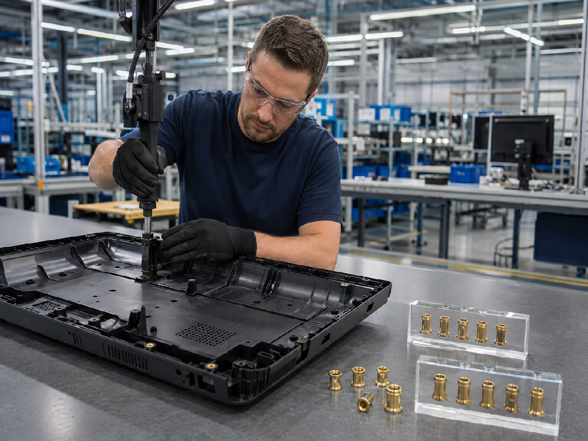
High-performance knurled brass inserts require a material that can be manufactured accurately while providing suitable mechanical and thermal behavior during installation.
Brass is widely used for plastic threaded inserts because it combines:
Excellent machinability
Good thermal conductivity
Good electrical conductivity
Useful corrosion resistance
Suitable strength for many plastic-housing applications
Good compatibility with heat-set and ultrasonic insertion processes
However, material standards such as ASTM B16 or EN 12164 describe particular brass material forms and compositions. They do not automatically constitute a complete product standard for a finished threaded insert.
For procurement, the finished insert drawing should therefore specify:
Brass alloy
Thread size
Thread tolerance
Outside diameter
Length
Knurl geometry
Surface finish
Dimensional tolerances
Required mechanical performance
Applicable inspection requirements
| Material Designation | International / Material Reference | Chemical Profile | Engineering Characteristics | Primary Industrial Application |
|---|---|---|---|---|
| Free-Cutting Brass | ASTM B16 / UNS C36000; EN 12164 CW603N may be used as a material reference where applicable | Copper-zinc alloy with lead content characteristic of free-cutting grades | Excellent machinability, good thermal and electrical conductivity, suitable for precision internal threads and many heat-set applications | Electric power tools, automotive sensor housings, electrical junction boxes, electronic enclosures |
| Ductile / Machining Brass | EN 12164 / EN 12165 grades selected according to required product form and alloy | Copper-zinc alloy selected according to mechanical and manufacturing requirements | Good balance of machinability, strength, thermal conductivity, and insert-forming performance | Consumer appliances, electrical housings, industrial equipment |
| Lead-Free Brass | Applicable lead-free copper alloy specification selected according to application and regulatory requirements | Copper-zinc or other copper alloy chemistry without intentionally added lead, depending on grade | Suitable where lead restrictions or specific environmental requirements apply; exact mechanical and machining behavior depends on alloy | Medical equipment, electrical components, fluid-handling equipment, consumer products |
| Stainless Steel | Grade selected according to application and applicable stainless-steel fastener/material specification | Austenitic or other stainless alloy depending on environment and strength requirements | Higher corrosion resistance and different thermal behavior compared with brass; installation process must be validated accordingly | Marine equipment, medical equipment, chemical environments, high-corrosion applications |
| Aluminum Alloy | Alloy selected according to application and applicable aluminum material specification | Aluminum alloy chemistry depends on required strength, weight, and machinability | Low density and high strength-to-weight ratio; thermal installation behavior differs from brass | Aerospace, lightweight electronics, EV components, portable equipment |
For many brass threaded inserts for plastic, free-machining brass is attractive because the insert requires accurate internal threads and controlled external knurl geometry.
However, the best brass grade is not determined by machinability alone.
The engineering selection should consider:
Thread strength
Insert dimensions
Knurl depth
Installation temperature
Ultrasonic response
Electrical conductivity
Corrosion requirements
Regulatory requirements
Customer material restrictions
Production process
Where lead-free requirements apply, the exact alloy should be specified rather than simply describing the insert as “lead-free brass.”
This is particularly important for automotive electronics, medical devices, electrical equipment, and other applications with restricted-substance requirements.
The external profile of a post-mold knurled brass insert strongly influences its resistance to axial pull-out and rotational movement.
The external geometry creates mechanical engagement with the surrounding polymer.
Depending on the design, this may include:
Straight knurling
Diamond knurling
Diagonal knurling
Opposing knurl bands
Annular grooves
Undercut features
Stepped outer diameters
Chamfered pilot sections
Head or flange features
JUXIN FASTENERS can develop custom external geometries according to the plastic material, installation method, available boss geometry, and required mechanical performance.
                  PRECISION KNURLED INSERT GEOMETRY

            +---------------------------------------+
            |  [Round Head Guide / Chamfer Ring]    |
            |       Leading Alignment Section       |
            +---------------------------------------+
            |  [Stepped Outer Diameter – Step 1]    |
            |      Progressive Polymer Entry        |
            +---------------------------------------+
            |  [Diagonal / Diamond Knurl Band 1]    |
            |      Rotational & Axial Retention     |
            +---------------------------------------+
            |  [Central Annular Relief / Groove]    |
            |      Polymer Flow / Retention Zone    |
            +---------------------------------------+
            |  [Diagonal / Diamond Knurl Band 2]    |
            |      Additional Retention Area        |
            +---------------------------------------+
            |  [Stepped Outer Diameter – Step 2]    |
            |      Controlled Polymer Displacement  |
            +---------------------------------------+
External knurl geometry plays an important role in rotational torque resistance.
A knurled brass insert with properly designed diagonal or diamond features creates multiple mechanical contact areas between the brass insert and polymer.
Opposing or multi-directional knurl patterns can provide resistance against rotation in both directions.
This is particularly relevant where the mating screw is installed using:
Electric screwdrivers
Pneumatic screwdrivers
Automatic screwdriving equipment
Torque-controlled assembly tools
Repeated service cycles
However, knurl geometry alone does not guarantee a specific torque value.
Actual rotational resistance depends on:
Polymer strength
Polymer temperature
Insert diameter
Knurl depth
Knurl pitch
Insert length
Boss diameter
Installation quality
Screw torque
Environmental aging
Therefore, the required rotational torque should be validated using the complete plastic-insert assembly.
A stepped outer diameter can help control how the insert enters the pilot hole and how the softened polymer moves around the external retention geometry.
During heat installation, the thermoplastic surrounding the insert becomes locally softened.
A properly designed external profile allows the polymer to flow around the knurl or groove structure without requiring excessive insertion force.
This can help reduce:
Boss cracking
Excessive radial expansion
Localized polymer damage
Insert misalignment
Installation-force variation
However, the stepped profile should be designed together with the pilot-hole diameter and boss geometry.
A smaller or more aggressive insert profile is not automatically better because excessive displacement can increase hoop stress in brittle or highly reinforced plastics.
Diamond knurled brass inserts use intersecting diagonal features to create multiple mechanical engagement points.
This type of external profile can provide useful resistance against:
Axial pull-out
Clockwise rotation
Counter-clockwise rotation
The final performance is determined by the actual knurl dimensions and the polymer's ability to resist deformation.
For glass-filled nylon inserts, for example, the designer should evaluate the interaction between the knurl geometry and the glass-fiber-reinforced polymer rather than assuming that a larger knurl automatically produces greater retention.
An unknurled leading section or chamfer can help guide the insert into the pilot hole.
This feature is particularly useful for automated heat-set insert installation and high-speed assembly.
The leading section can help:
Center the insert
Reduce initial insertion resistance
Improve alignment
Reduce the chance of angular installation
Protect the first engagement section of the insert
For automated production, insert orientation, tooling alignment, insertion speed, and verticality should be controlled together.
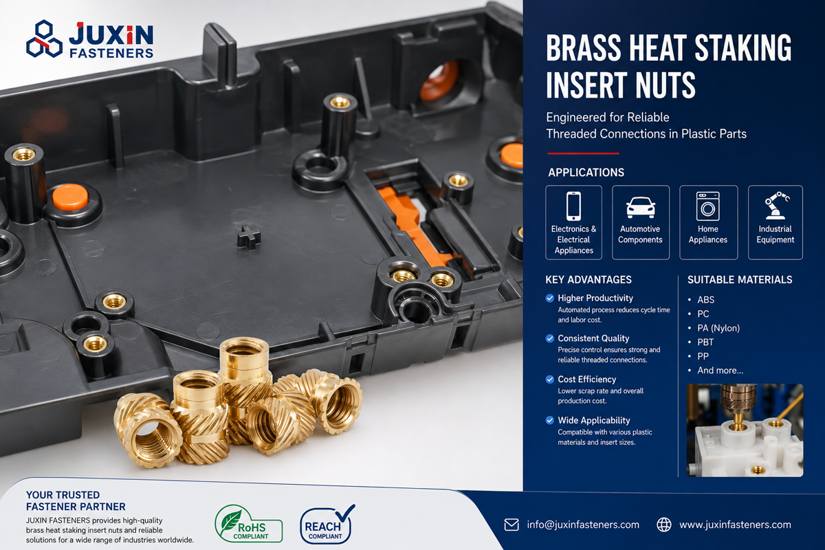
Separating plastic molding from insert installation can provide manufacturing flexibility for certain high-volume plastic components.
Instead of:
Place metal insert in mold → Inject polymer → Cool → Eject
the production sequence becomes:
Injection molding → Fast ejection → Inspection → Post-mold insert installation
This allows the injection-molding process and metal-insert assembly process to be optimized independently.
+-----------------------------------------------------------------------------------------------+
|                                MANUFACTURING WORKFLOW COMPARISON                              |
+-----------------------------------------------------------------------------------------------+
|  MOLDED-IN METHOD:                                                                            |
|  Place metal part in mold --> Inject polymer --> Cool down --> Eject                          |
|  *Considerations: insert placement, mold tooling, insert movement, polymer flow,             |
|  differential thermal expansion, and potential tooling complexity.                            |
|                                                                                               |
|  AFTER-MOLDING METHOD:                                                                        |
|  Injection molding --> Eject plastic part --> Inspect --> Heat / Ultrasonic / Press Insert   |
|  *Potential benefits: simpler molding workflow, flexible assembly stations, easier           |
|  process adjustment, and separation of molding and insert-installation operations.            |
+-----------------------------------------------------------------------------------------------+
| Performance & Operational Metric | Molded-In Fastener Insertion | After-Molding Insertion |
|---|---|---|
| Injection Molding Cycle Time | Insert placement and encapsulation are integrated into molding process and may increase process complexity | Metal insert is installed after molding; the molding cycle can be optimized independently |
| Tooling & Mold Risk | Requires insert positioning and retention inside mold; displaced inserts can potentially damage tooling | Insert installation occurs outside the mold, reducing metal-insert interference with molding tooling |
| Residual Polymer Stress | Metal insert is encapsulated during polymer cooling; differential thermal expansion may affect residual stress | Plastic part cools before insert installation; thermal or ultrasonic energy is localized during assembly |
| Thread Serviceability | Provides an integrated metal thread when properly molded | Provides a metal thread installed after molding and can simplify inspection/replacement during production |
| Scrap & Quality Control | Insert-related defects may be discovered after molding and can affect the molded component | Insert installation can be inspected as a separate assembly operation |
| Capital Efficiency | May require specialized mold features, insert loading systems, or automation | Can use separate insertion equipment and tooling while keeping the molding tool simpler |
| Production Flexibility | Insert location is fixed by molding-tool design | Post-mold insertion can allow greater flexibility in assembly-line configuration |
| High-Volume Automation | Highly suitable when the insert and molding process are already optimized | Highly suitable when automated heat-set, ultrasonic, or press insertion can be integrated downstream |
The correct process should be selected based on total manufacturing economics and engineering performance rather than assuming that post-molding insertion is universally superior.
To achieve reliable pull-out strength and rotational torque resistance in thermoplastic components such as PA66, PBT, ABS, Polycarbonate, and reinforced engineering plastics, the insert and plastic boss must be designed as one mechanical system.
Important design parameters include:
Insert outside diameter
Insert length
Knurl diameter
Knurl depth
Knurl pitch
Pilot-hole diameter
Boss outside diameter
Boss wall thickness
Polymer grade
Glass-fiber content
Installation temperature
Installation force
Insertion speed
Screw tightening torque
Operating temperature
Environmental exposure
During thermal installation, the brass insert is heated and pressed into the thermoplastic component.
The objective is to soften or melt the surrounding polymer locally so that the material flows around the knurled external profile.
The insert should not simply be heated to a universal temperature.
The appropriate process window depends on:
Polymer melting or softening behavior
Glass-transition temperature
Heat-deflection characteristics
Insert geometry
Insert mass
Heating method
Tool design
Insertion speed
Dwell time
Polymer moisture condition
Component geometry
For example, ABS, PC, PA66, and glass-filled PBT do not share one universal heat-staking temperature.
Therefore, the following ranges should be treated as development starting points rather than fixed production standards:
                  HEAT-SET INSERT PROCESS DEVELOPMENT

  Host Polymer Matrix         Typical Thermal Behavior       Process Development Focus
  -----------------------------------------------------------------------------------------
  ABS / Polycarbonate (PC)    Thermoplastic softening /      Establish insert temperature,
                              melt behavior depends on grade insertion speed and dwell time

  Polyamide 66 (PA66)         High-temperature engineering  Control heat input, moisture,
                              thermoplastic                 insertion force and cycle time

  Glass-Filled PBT            Reinforced engineering         Validate polymer flow around knurls,
                              thermoplastic                  boss cracking and retention
Actual production settings should be established experimentally for the specific resin and insert combination.
A controlled heat-set process normally monitors:
Insert temperature
Tool temperature
Insertion force
Insertion depth
Insertion speed
Heating time
Cooling time
Boss deformation
Final insert height
Insert perpendicularity
The goal is to achieve sufficient polymer flow around the knurl without overheating or degrading the surrounding plastic.
Ultrasonic brass inserts are installed using high-frequency mechanical vibration.
The vibration generates localized heat at the plastic-metal interface, allowing the polymer to flow around the external knurl.
Ultrasonic insertion can be highly effective for automated production, but the process requires validation of:
Amplitude
Weld/insertion time
Downforce
Tool geometry
Insert geometry
Polymer grade
Boss geometry
A process that works for unfilled ABS may not work identically for PA66-GF30 or PBT-GF30.
Therefore, ultrasonic insertion parameters should always be developed against the actual material and insert design.
The ultimate axial holding capacity of an embedded knurled insert is related to the effective shear area between the polymer and the external retention geometry.
A simplified engineering relationship can be written as:
F_axial ≈ π × D_eff × L_eng × τ_eff
Where:
D_eff = effective engagement diameter
L_eng = effective engagement length
τ_eff = effective shear strength of the polymer/insert interface
For a knurled insert, the actual load path is more complex than a simple cylindrical shear surface.
The result is influenced by:
Knurl height
Knurl pitch
Groove geometry
Polymer flow
Local stress concentration
Boss geometry
Polymer orientation
Installation quality
Temperature
Aging
Therefore, the equation should be used for conceptual sizing rather than as a guaranteed prediction of finished-part pull-out force.
Rotational resistance is controlled by the shear and bearing interaction between the external knurl profile and surrounding polymer.
A simplified design concept is:
T_resistance ∝ A_engagement × r_eff × τ_eff
Where:
A_engagement = effective polymer engagement area
r_eff = effective radial distance from the insert centerline
τ_eff = effective polymer shear resistance
Increasing insert diameter, engagement length, and effective external retention can increase resistance, but only when the surrounding boss has sufficient structural capacity.
This is why simply increasing knurl depth may increase installation force and cracking risk without producing a proportional improvement in finished-joint performance.
The plastic boss is frequently the limiting component in a threaded insert joint.
A properly designed plastic boss for brass threaded inserts should provide sufficient material around the insert to resist radial expansion and applied assembly loads.
The design should consider:
Boss diameter
Boss height
Wall thickness
Fillet radius
Draft angle
Insert diameter
Knurl depth
Pilot-hole diameter
Polymer shrinkage
Glass-fiber orientation
Screw torque
Stress cracking can occur when installation forces exceed the local strength of the polymer.
The risk may increase with:
Brittle polymer grades
Excessive interference
Large knurl depth
Small boss diameter
Thin boss walls
Excessive installation speed
Excessive heat
Poorly controlled cooling
High glass-fiber loading
Sharp geometric transitions
A practical mitigation strategy is to optimize the complete system rather than simply reducing insert dimensions.
Potential corrective actions include:
Increasing boss diameter
Increasing local wall thickness
Reducing excessive interference
Adjusting pilot-hole diameter
Modifying knurl geometry
Reducing insertion speed
Optimizing thermal energy
Adding a suitable boss fillet
Adjusting polymer grade or reinforcement
Glass-filled PA66 and PBT provide high stiffness and strength but can be less tolerant of aggressive insert interference.
Fiber orientation around the boss can also influence local strength.
Therefore, knurled brass inserts for PA66-GF and PBT-GF should be validated using actual molded production parts.
The pilot-hole diameter should be established from:
Insert dimensions
Resin grade
Fiber percentage
Molding shrinkage
Production tolerance
Installation method
Required retention performance
There should not be one universal +0.08 mm or +0.15 mm correction for every glass-filled polymer.
This is an important distinction for tooling engineers because resin grade and processing conditions can significantly affect the correct pilot-hole dimension.
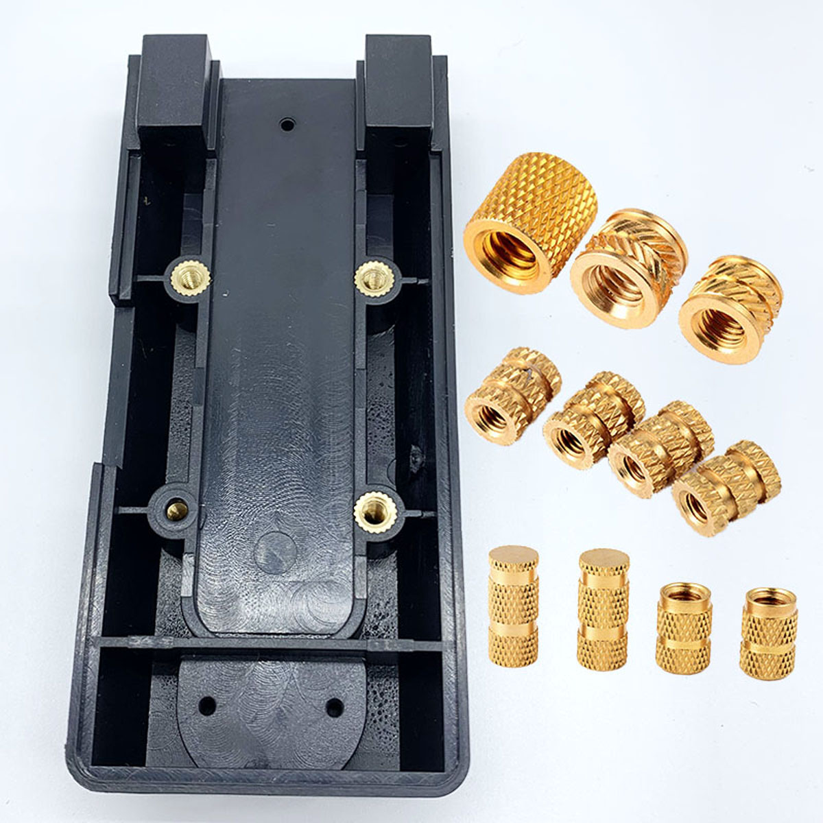
JUXIN FASTENERS supplies knurled brass threaded inserts and other threaded insert solutions for demanding plastic-component applications.
Typical applications include:
Motor housings
Gear covers
Handle assemblies
Battery housings
Switch housings
Charging equipment
Tool body components
Power tools can expose plastic fasteners to:
Dynamic vibration
Repeated impact
Screw-driving torque
Thermal cycling
Repeated service assembly
Knurled brass inserts can provide a reusable metallic thread while distributing load into the surrounding plastic.
For glass-filled nylon housings, insert geometry and boss design should be validated against the actual assembly torque and service environment.
Potential applications include:
Electronic control units
Sensor housings
Battery junction boxes
Automotive connectors
Plastic control modules
Electrical enclosures
EV component housings
Automotive applications may involve wide temperature fluctuations, vibration, humidity, and chemical exposure.
Instead of applying a universal temperature claim such as “−40°C to +150°C” to every insert, the complete assembly should be validated against the actual customer specification and operating environment.
Important validation areas may include:
Thermal cycling
Vibration
Humidity
Chemical exposure
Pull-out retention
Rotational torque
Thread integrity
Dimensional stability
Applications include:
Circuit breakers
Terminal blocks
Switchgear
Electrical control panels
Meter housings
Power-control equipment
Industrial electronic enclosures
Brass can be attractive in electrical applications because of its electrical and thermal conductivity as well as its machinability.
Where electrical grounding or conductivity is part of the design, however, the complete contact path and surface condition must be specified and validated.
Potential applications include:
Laptops
Handheld diagnostic instruments
Smart home equipment
Telecommunications equipment
Small electronic housings
Appliance controls
Small M1.6, M2, M2.5, and M3 brass threaded inserts can be used where compact reusable internal threads are required, subject to the available insert geometry and component design.
For thin-wall electronic housings, the main engineering challenge is often preventing:
Boss bulging
Sink marks
Cracking
Insert misalignment
Cosmetic deformation
Thread distortion
A properly designed post-mold installation process can help maintain consistent appearance and assembly performance.
For procurement specialists and supply chain developers issuing RFQs, specifying only “brass insert” is normally insufficient.
A professional threaded insert procurement specification should identify the complete part geometry and installation requirements.
                    JUXIN FASTENERS ORDERING SPECIFICATION

   [Insert Type] / [Thread Size & Pitch] / [Length]
   / [Material] / [External Geometry] / [Surface Finish]
   / [Plastic Material] / [Installation Method]

   Example:

   Knurled Brass Insert
   / M4 x 0.7
   / 8.5 mm
   / Brass CW603N
   / Dual Diamond / Diagonal Knurl
   / Plain
   / PA66-GF30
   / Heat-Set Installation

   Note:
   This is an RFQ specification example, not a universal JUXIN FASTENERS
   catalog part number. Final dimensions and material should be confirmed
   against the applicable engineering drawing.
| Procurement Parameter | Technical Options | Compliance & Quality Considerations |
|---|---|---|
| Insert Architecture | Single Knurl, Diamond Knurl, Dual Knurl, Stepped Knurl, Grooved, Custom Profile | External geometry should be selected according to polymer and required retention |
| Thread Dimensions | Metric M1.6 to M12 or other available sizes; Unified threads where required | Specify thread size, pitch, tolerance, and mating screw requirements |
| Thread Tolerance | Internal thread according to customer drawing / applicable thread standard | Do not assume one tolerance such as ISO 6H is appropriate for every finished insert |
| Insert Length | Application-specific | Determine according to required engagement and boss height |
| Material | Free-Cutting Brass, Lead-Free Brass, Aluminum, Steel, Stainless Steel | Specify exact material grade rather than generic material names |
| External Geometry | Straight Knurl, Diamond Knurl, Diagonal Knurl, Opposing Knurl, Groove, Undercut | Determines polymer retention and installation behavior |
| Surface Treatment | Plain, Nickel, Zinc, or other specified finish | Select according to corrosion, appearance, friction, electrical, and environmental requirements |
| Plastic Material | PA66, PA66-GF, PBT, PBT-GF, ABS, PC, PC/ABS, PPS, PEEK and other engineering polymers | Resin grade and filler percentage should be specified |
| Installation Method | Heat-Set, Thermal, Ultrasonic, Press-In, Other Post-Mold Method | Must be compatible with insert geometry and polymer |
| Assembly Equipment | Manual, Semi-Automatic, Automatic Insertion System | Tooling and process settings should be validated for production conditions |
| Performance Requirement | Pull-Out Force, Rotational Torque, Installation Force | Define acceptance values based on actual application requirements |
| Environmental Requirement | Temperature, Humidity, Vibration, Thermal Cycling, Chemicals | Specify actual operating and validation conditions |
| Quality Documentation | Material Certificate, Dimensional Report, Inspection Report, Samples, PPAP where required | Documentation should be aligned with customer purchasing requirements |
For custom knurled brass inserts for plastic, procurement teams should provide:
1. Insert Type: Heat-Set / Ultrasonic / Press-In / Self-Tapping / Molded-In / Custom
2. Thread Size: M1.6 / M2 / M2.5 / M3 / M4 / M5 / M6 / M8 / M10 / M12 or specified Unified thread
3. Thread Pitch: Specify metric pitch or Unified thread designation
4. Thread Tolerance: Specify required internal-thread tolerance
5. Insert Length: Specify nominal length
6. Outside Diameter: Specify nominal body and knurl diameter
7. Knurl Geometry: Straight / Diamond / Diagonal / Opposing / Stepped / Custom
8. Material: Brass / Lead-Free Brass / Aluminum / Steel / Stainless Steel
9. Surface Finish: Plain / Nickel / Zinc / Other
10. Plastic Resin: PA66 / PA66-GF / PBT / PBT-GF / ABS / PC / PC-ABS / PPS / PEEK / Other
11. Plastic Thickness: Specify nominal and minimum thickness
12. Boss Dimensions: Specify boss diameter, height, wall thickness, and available installation space
13. Pilot Hole: Specify existing hole diameter and tolerance if known
14. Installation Method: Heat / Ultrasonic / Press / Other
15. Required Pull-Out Force: Specify minimum acceptance value
16. Required Rotational Torque: Specify minimum acceptance value
17. Assembly Screw: Specify screw size, length, thread, and tightening torque
18. Environmental Conditions: Temperature, humidity, chemicals, vibration, thermal cycling
19. Annual Quantity: Estimated yearly demand and batch quantity
20. Quality Documentation: Inspection report, material certificate, PPAP, sample approval, or other customer-specific requirements
Explore the JUXIN FASTENERS technical library to optimize fastening systems across different materials and component categories:
Threaded Inserts for Plastics: Engineering Installation Guide
https://www.juxinfasteners.com/industrial-solutions/thread-insert-nuts-engineering-installation-guide/
In-depth analysis of self-tapping, press-in, heat-set, molded-in, and other threaded insert solutions for plastic components.
Specialized Nut Engineering Guide: Cap Nuts, Wing Nuts & Titanium Flange Nuts
https://www.juxinfasteners.com/industrial-solutions/cap-nuts-wing-nuts-titanium-flange-nuts-engineering-guide/
Material selection and engineering considerations for specialized nut applications.
Bolt Exposed Thread Length Standards & High-Vibration Lock Nuts
https://www.juxinfasteners.com/technical-guide/bolt-exposed-thread-length-anti-loosening-fasteners/
Structural thread engagement, exposed thread length, and locking-nut selection for vibration-sensitive applications.
Self-Clinching Fasteners
https://www.juxinfasteners.com/products/self-clinching-fasteners/
Compare permanent mechanical fastening solutions for sheet metal with threaded inserts used in plastic components.
Weld Fasteners
https://www.juxinfasteners.com/products/weld-fasteners/
Related permanent fastening solutions for fabricated sheet-metal assemblies.
Automotive Fasteners & Hardware Parts
https://www.juxinfasteners.com/products/automotive-fasteners-hardwares-parts/
Related fastening components for automotive and EV manufacturing applications.
A common mistake in plastic fastening is to assume that a more aggressive external knurl will automatically produce a stronger insert.
In reality, insert retention is a system property.
The load path is:
Assembly Screw → Internal Thread → Brass Insert → External Knurl → Polymer Boss → Plastic Component
If the internal thread is strong but the boss cracks, the joint fails.
If the boss is strong but the insert rotates, the joint fails.
If pull-out strength is sufficient but rotational torque resistance is too low, the assembly can still fail during screw installation.
Therefore, engineers should balance:
Insert diameter
Insert length
Knurl geometry
Knurl depth
Pilot-hole diameter
Boss diameter
Boss wall thickness
Polymer grade
Glass-fiber content
Installation temperature
Installation force
Screw torque
Environmental exposure
These are different performance characteristics.
Pull-out strength measures resistance against axial extraction.
Rotational torque resistance measures resistance against rotation.
Increasing insert length may significantly improve pull-out resistance but may have a smaller effect on rotational torque if the boss geometry remains unchanged.
Increasing insert diameter can increase the effective retention radius, but may also increase installation force and hoop stress.
Increasing knurl depth can increase mechanical engagement, but may increase cracking risk in brittle or glass-filled polymers.
This is the type of engineering trade-off that should be evaluated before selecting a knurled brass threaded insert.
For procurement and strategic sourcing teams, the ideal supplier should be capable of supporting both standard brass threaded inserts and custom insert geometries.
JUXIN FASTENERS supports sourcing and manufacturing requirements for:
Knurled brass inserts
Brass threaded inserts
Heat-set brass inserts
Ultrasonic brass inserts
Press-in brass inserts
Self-tapping inserts
Threaded inserts for injection molded plastics
Plastic insert nuts
Custom thread inserts
Aluminum inserts
Steel inserts
Stainless steel inserts
Custom cold-formed fasteners
CNC-machined fastening components
Manufacturing processes may include:
Cold forming
CNC machining
Automatic turning
Stamping
Threading
Knurling
Surface finishing
Dimensional inspection
For custom projects, engineering drawings and actual application conditions are especially valuable.
A complete technical inquiry should include:
2D engineering drawing
3D CAD model where available
Thread size
Insert length
Outside diameter
Knurl geometry
Material
Surface finish
Plastic resin
Glass-fiber percentage
Component thickness
Boss dimensions
Pilot-hole diameter
Installation method
Required pull-out force
Required rotational torque
Assembly screw torque
Operating temperature
Environmental conditions
Annual quantity
Packaging requirements
This information allows the supplier to evaluate the insert as part of the complete plastic fastening system rather than as an isolated metal component.
JUXIN FASTENERS supplies standard and custom fastening components for OEM, automotive, EV, electronics, power tools, industrial machinery, electrical equipment, and other manufacturing applications.
Our manufacturing capabilities include cold forming, CNC machining, turning, stamping, knurling, threading, and inspection processes selected according to product geometry, material, and production requirements.
For knurled brass inserts for plastic, our technical evaluation can focus on:
Brass material selection
Thread size and tolerance
Knurl geometry
Insert length
Pilot-hole requirements
Plastic boss design
Heat-set installation
Ultrasonic insertion
Press-fit installation
Pull-out performance
Rotational torque
Surface treatment
Environmental requirements
Custom dimensions
Contact our engineering and sourcing team for drawings, samples, technical specifications, and custom manufacturing inquiries.
Official Corporate Website:
https://www.juxinfasteners.com
Engineering & Sourcing Support:
info@juxinfasteners.com
Core Manufacturing Capabilities:
Precision Knurled Brass Inserts, Brass Threaded Inserts, Thread Inserts for Plastics, Heat-Set Inserts, Ultrasonic Inserts, Custom Threaded Inserts, Precision Cold-Formed Fasteners, and Custom CNC Turned Hardware.
 MORE NEWS

Sep. 25, 2026

Sep. 25, 2026

Sep. 25, 2026
Contact Us
Tel.:
+86 020 8621 0320
+86 020 3121 6067
E-mail:
Technical Support:
Navigation
SEND INQUIREY