
Call Us
+86 136 6007 9809
Call Us
+86 136 6007 9809

Aug. 21, 2023
Automotive blind rivet nuts provide a practical way to create internal threads in sheet metal, formed panels, brackets, enclosures and assemblies where access to the rear side is limited.
For automotive and EV applications, the fastener must do more than simply provide an internal thread.
The engineering design may need to address sheet thickness, hole geometry, grip range, pull-through resistance,
pull-out resistance, torque-out resistance, spin-out risk, vibration, corrosion, installation access and repeated service.
Large-cap automotive blind rivet nuts are particularly useful when a larger bearing area is required at the visible side of the panel.
Anti-rotation body geometries, such as knurled, semi-hex or hex bodies, can also be selected when rotational resistance is important during screw installation and service.
JUXIN FASTENERS supplies custom and application-specific fasteners for industrial B2B requirements.
For automotive projects, the correct selection should be based on the complete joint rather than the fastener name alone.
An automotive blind rivet nut is a threaded insert installed into a prepared hole from one side of a sheet or component.
During installation, the body of the rivet nut deforms behind the parent material and creates a clamped section.
The internal thread then provides a reusable threaded connection for a mating screw or bolt.
The major advantage is single-sided installation.
This makes blind rivet nuts useful where the rear side of the panel is inaccessible after assembly, where welding is undesirable,
or where a formed sheet does not provide enough material for a conventional tapped thread.

Automotive structures increasingly combine stamped steel, aluminum, coated sheet metal, composite panels and lightweight assemblies.
Creating a reliable internal thread in these materials can require different fastening approaches depending on thickness, access and load.
Blind rivet nuts can provide:
Single-sided installation
Internal metric or other specified threads
Installation into relatively thin sheet
Serviceable threaded attachment
Integration into existing sheet-metal manufacturing processes
Flexible placement where rear access is restricted
Options for different body and flange geometries
Custom configurations for OEM assemblies
The correct design depends on the parent material and the actual joint loads.
Automotive blind rivet nuts can be used across many non-identical applications.
Typical examples include:
Body panels
Door structures
Interior trim support brackets
Instrument panel brackets
Seat-related brackets
Underbody shields
Wheel-area components
Electrical enclosures
Battery-related enclosure components
Thermal-management equipment
Charging equipment
Sensor brackets
Wiring and cable-management brackets
HVAC components
Commercial vehicle bodywork
Truck and bus equipment
Service-access panels
Industrial vehicle structures
The appropriate rivet nut design should always be selected from the actual assembly requirements.
A large-cap rivet nut has a larger flange or head diameter than a conventional configuration.
The purpose is not simply to make the fastener look stronger.
A larger bearing surface can change how installation forces and service loads are transferred into the parent sheet.
This can be valuable where the surrounding sheet is relatively thin or where a larger contact area is required around the hole.
However, flange diameter should not be treated as a universal indicator of joint strength.
No.
This is an important Information Gain point for automotive fastener selection.
Pull-through behavior depends on the complete joint, including:
Flange diameter
Flange thickness
Parent-sheet thickness
Parent-sheet material
Hole diameter
Hole quality
Edge distance
Applied load
Load direction
Installation condition
Local sheet deformation
Fastener geometry
A larger cap may increase the bearing area, but it does not independently determine the final failure load.
For engineering validation, the actual fastener and actual parent material should be tested under the intended assembly conditions.
A standard-head rivet nut may be sufficient when the panel and load conditions are favorable.
A large-cap design can become attractive when the engineer wants greater flange coverage or a different load-transfer interface.
The selection should therefore begin with the joint requirement rather than the assumption that the largest available flange is always preferable.
A rivet nut must resist rotation when the mating screw is installed or removed.
This is different from resisting axial pull-out.
A fastener can have acceptable axial retention while still experiencing rotational movement if the body-to-hole interface is not suitable for the application.
This distinction is especially important in automotive assembly.
Knurled rivet nuts use external surface geometry to increase mechanical interaction with the parent material.
The knurl can help resist rotation after installation when properly matched to the hole and parent material.
However, the performance of a knurled body depends on the actual installation condition.
Hole size, material thickness, material strength and installation deformation all affect the result.
Hex and semi-hex body configurations create a non-round interface with the mounting hole.
This geometry can provide a mechanical anti-rotation feature when the hole and installation process are properly matched.
For automotive applications where assembly torque is significant, the engineer should consider body geometry together with the mating screw, installation torque and parent sheet.
Large-cap and anti-rotation features solve different parts of the joint problem.
The large cap primarily addresses the interface around the front side of the panel.
The anti-rotation body addresses rotational behavior inside the mounting hole.
Combining these features can be useful when both bearing area and rotational resistance are important.
The two features should therefore be evaluated separately before being considered as one complete design.
One of the most frequently overlooked factors in rivet nut selection is the mounting hole.
The rivet nut does not operate independently of the hole.
Important parameters include:
Nominal hole diameter
Hole tolerance
Hole roundness
Burr condition
Punching quality
Laser-cut edge condition
Coating thickness
Parent material
Local sheet deformation
A rivet nut selected without controlling the hole condition can produce inconsistent installation results.
An oversized hole can reduce the effectiveness of an anti-rotation body.
For a round knurled rivet nut, insufficient engagement may reduce the mechanical interaction between the external knurl and the parent sheet.
For a hex or semi-hex rivet nut, an unsuitable hole geometry can prevent the body from functioning as intended.
Therefore, the mounting-hole specification should be treated as part of the fastener specification.
Grip range describes the range of parent-material thicknesses for which a particular rivet nut configuration is designed to be installed.
It should not be treated simply as the nominal thickness of one sheet.
Assemblies may include:
Single sheet
Overlapping sheets
Brackets
Coated panels
Washers
Reinforcement layers
Local stamped features
The total material stack-up should therefore be considered when selecting the rivet nut.
Automotive assemblies frequently contain more than one layer.
Before selecting the rivet nut, the engineer should identify:
Minimum stack thickness
Maximum stack thickness
Hole diameter
Accessibility
Required thread
Required flange geometry
Required anti-rotation performance
Installation tool access
This information allows the supplier to select a suitable body length and grip range.
These terms should not be used interchangeably.
The installed fastener or its flange moves through or damages the parent sheet under axial loading.
The installed insert separates from the parent material under an axial load.
The fastener or its interface fails under rotational loading.
The rivet nut rotates in the hole rather than remaining stationary while the mating screw is tightened or removed.
These are different failure modes and require different engineering considerations.
Automotive production often uses powered screwdriving or bolting equipment.
If the rivet nut begins rotating before the mating screw reaches the required assembly condition, several problems can occur:
Assembly torque may not be achieved as intended.
The joint may require rework.
The fastener may become difficult to remove.
The parent sheet may be damaged.
Production cycle time may increase.
Serviceability may be affected.
For this reason, anti-rotation should be treated as a specific engineering requirement rather than an assumed benefit.
Thin automotive panels can be sensitive to local deformation.
The flange geometry, installation condition and parent material must work together.
A larger flange can distribute contact over a broader area, but the engineer should still evaluate:
Local panel stiffness
Edge distance
Hole diameter
Material thickness
Material condition
Installation deformation
Service loading
A large head does not eliminate the need for joint validation.
Automotive panels may be manufactured from different materials.
Common examples include:
Carbon steel
High-strength steel
Stainless steel
Aluminum alloys
Coated steel
Other engineered sheet materials
The same rivet nut geometry should not automatically be assumed suitable for every material.
The deformation behavior of the parent sheet can materially affect installation and joint performance.
Steel rivet nuts are widely considered when the assembly requires a robust threaded insert and the parent structure is compatible with steel fastening components.
Material and finish selection should consider:
Mechanical requirements
Corrosion environment
Parent material
Mating screw material
Coating compatibility
Assembly conditions
Service environment
The exact material grade should be specified according to the drawing or customer requirement.
Stainless steel rivet nuts can be considered where corrosion resistance is important or where the assembly requires a stainless fastening material.
However, stainless steel selection should not be reduced to simply choosing “304” or “316.”
The complete environment should be evaluated, including:
Moisture
Salt exposure
Chemical exposure
Temperature
Mating materials
Galvanic interaction
Surface condition
Where stainless steel fastener grades are specified, the applicable ISO 3506 requirements should be checked for the relevant fastener type and scope.
ISO 3506-1 and ISO 3506-2 cover specified stainless steel bolts/screws/studs and nuts respectively, rather than serving as a generic standard for every rivet-nut geometry.
Aluminum rivet nuts can be considered where weight reduction and material compatibility are important.
However, lower density does not automatically mean a lower-mass or better-performing joint.
The engineer should consider:
Required thread capacity
Parent sheet material
Corrosion environment
Joint loads
Installation behavior
Mating fastener material
For EV applications, the complete enclosure fastening system should be evaluated rather than selecting aluminum inserts solely for weight.
When dissimilar metals are joined, galvanic corrosion may become a system-level concern.
This can be particularly relevant in automotive structures containing:
Aluminum panels
Steel brackets
Stainless fasteners
Zinc-coated components
Moisture or road-salt exposure
Material selection, surface treatment, isolation and environmental exposure should therefore be considered together.
For carbon-steel automotive rivet nuts, the surface finish can be an important part of the specification.
Possible requirements may include:
Zinc-based protective coatings
Passivation
Other specified corrosion-protection systems
Customer-defined finishes
The exact coating should be specified by the customer drawing or purchasing specification rather than assumed from the product name.
Surface treatment is not independent of dimensional control.
Coating can influence:
External dimensions
Hole interaction
Thread condition
Assembly behavior
Corrosion performance
For tight automotive assemblies, the supplier should understand whether dimensions are specified before or after finishing.
Closed-end rivet nuts have a closed rear section.
This can be useful where the engineer wants the threaded insert to have a closed internal cavity rather than an open-through configuration.
Potential applications include selected:
Enclosures
Vehicle equipment housings
Electrical assemblies
Battery-related structures
Outdoor equipment
However, closed-end construction should not automatically be described as waterproof.
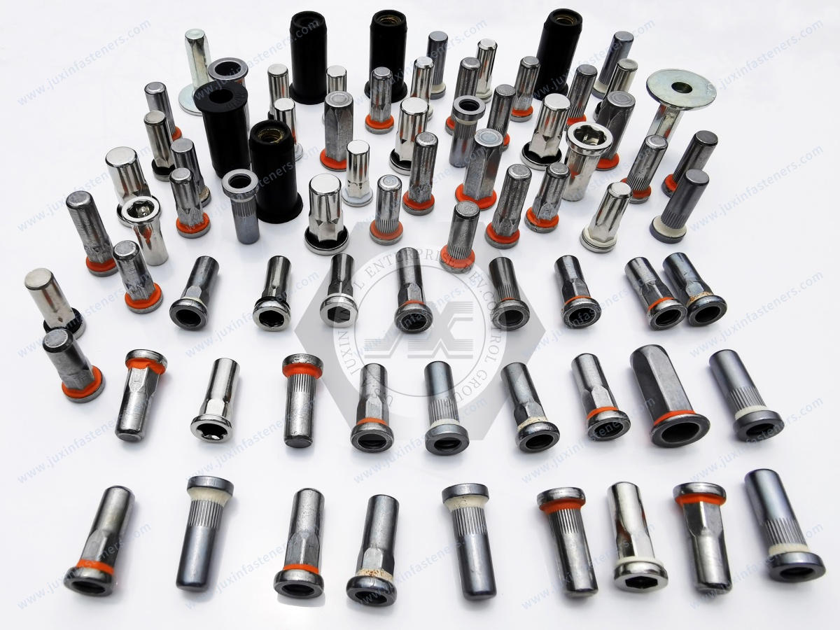
This distinction is particularly important for EV and automotive enclosure applications.
A closed-end rivet nut can help prevent a direct open passage through the insert, but enclosure ingress protection is an assembly-level requirement.
If an automotive enclosure has a required IP rating, the complete enclosure design, joint interface, gasket system, fastener installation and validation method must be evaluated.
The rivet nut alone should not be represented as automatically achieving a particular IP rating.
Where sealing is specifically required, a dedicated sealing rivet nut design may be considered.
The sealing feature and its interface with the parent panel should be defined by the application.
Important questions include:
What is the sealing interface?
What is the parent panel material?
What is the panel thickness?
What environmental exposure exists?
Is the requirement water resistance, fluid resistance or an enclosure IP rating?
What validation method applies?
The word “sealed” should therefore be tied to a defined engineering requirement.
Thread size should be selected according to the complete joint.
Important factors include:
Mating screw diameter
Required clamp load
Joint thickness
Available flange area
Service load
Installation space
Assembly tooling
Service access
M6 or M8 should not be presented as universally correct for automotive applications.
The rivet nut and mating screw work as one fastening system.
The engineer should consider:
Screw diameter
Thread pitch
Screw material
Screw strength
Screw length
Under-head geometry
Washer use
Coating
Installation torque
Service requirements
A rivet nut cannot be evaluated independently of the mating screw.
A mating screw creates rotational loading during installation and removal.
If the torque exceeds the rotational resistance of the installed rivet nut, spin-out may occur.
This means that the correct engineering question is not simply:
“What is the maximum torque of this rivet nut?”
A better question is:
“What rotational load must the installed rivet nut withstand in this specific joint?”
That distinction improves both product selection and validation.
Blind rivet nuts are installed through controlled deformation.
Installation stroke affects the final shape of the collapsed body behind the panel.
Too little deformation may result in inadequate installation.
Excessive or inappropriate deformation may damage the insert or parent material.
The supplier and customer should therefore agree on the installation method and required setting condition for application-specific parts.
Installation force is influenced by the fastener geometry, material and installation process.
The parent sheet also influences the final result.
A thin or soft panel may respond differently from a thicker or stronger sheet.
Therefore, the same rivet nut can behave differently when installed into different parent materials.
Automotive production may use powered installation tools to improve assembly consistency.
However, tool compatibility should be confirmed against the specific rivet nut design.
The relevant variables may include:
Thread mandrel
Installation stroke
Setting force
Tool nose
Access space
Fastener geometry
Production sequence
JUXIN FASTENERS can evaluate the required installation information from the customer drawing and application specification.
The hole should be controlled before installation.
Potential issues include:
Burrs
Excessive clearance
Irregular punching
Coating build-up
Distortion
Local cracking
Incorrect hole diameter
Poor hole preparation can create fastener failures that are incorrectly attributed to the rivet nut itself.
The distance from the rivet nut hole to a panel edge can affect local sheet deformation.
A fastener located too close to an edge may interact differently with the surrounding material than a fastener installed in a larger uninterrupted panel area.
Therefore, edge distance should be considered during design validation.
Large-cap automotive rivet nuts can be useful in selected body-panel applications where a broader front-side bearing interface is required.
Typical considerations include:
Panel thickness
Hole diameter
Flange diameter
Flange thickness
Body geometry
Thread
Grip range
Surface finish
Assembly access
The final selection should follow the drawing and validation requirements.
Automotive doors and interior structures can contain thin stamped components with restricted rear access.
Blind rivet nuts can provide threaded attachment points for:
Brackets
Trim-support components
Electrical components
Cable-management parts
Serviceable equipment
The fastener should be selected according to the local panel and assembly requirements.
Instrument-panel structures and electrical brackets can combine thin sheet, limited access and repeated service requirements.
For these applications, the design engineer should evaluate:
Thread size
Fastener head clearance
Anti-rotation requirement
Grip range
Installation access
Mating screw
Service removal
EV battery systems can contain extensive sheet-metal and enclosure fastening requirements.
Blind rivet nuts may be considered for selected:
Enclosure brackets
Covers
Service components
Cable-management structures
Thermal-management equipment
Electrical interfaces
Access panels
For battery enclosures, however, sealing, electrical isolation, corrosion and ingress protection should be treated as separate system requirements.
For related applications, see JUXIN FASTENERS' sealing blind rivet nut solutions for EV battery enclosures.
A fastener can contribute to an enclosure interface without independently defining the enclosure's environmental protection.
Where a customer requires an IP classification, the complete enclosure assembly must be validated against the applicable specification.
This prevents a common sourcing mistake: specifying an “IP-rated rivet nut” without defining how the fastener participates in the actual enclosure sealing system.
Underbody applications can expose fasteners to:
Water
Road contamination
Salt
Dirt
Temperature cycling
Mechanical vibration
Maintenance operations
Material and surface-treatment selection should therefore be based on the actual environment.
Corrosion protection should not be specified by a generic label alone.
Truck, bus and commercial vehicle structures may require threaded inserts in:
Body panels
Equipment cabinets
Service structures
Interior components
Electrical systems
Auxiliary equipment
The selection process remains the same: define the parent material, hole, grip, thread, loading and environment first.
The same large-cap and anti-rotation rivet nut principles can be applied outside automotive manufacturing.
Potential industries include:
Industrial machinery
Electrical equipment
HVAC equipment
Telecommunications
Renewable-energy equipment
Transportation equipment
Robotics
Automation
Commercial equipment
This makes automotive rivet nut technology relevant to a wider industrial fastening knowledge graph.
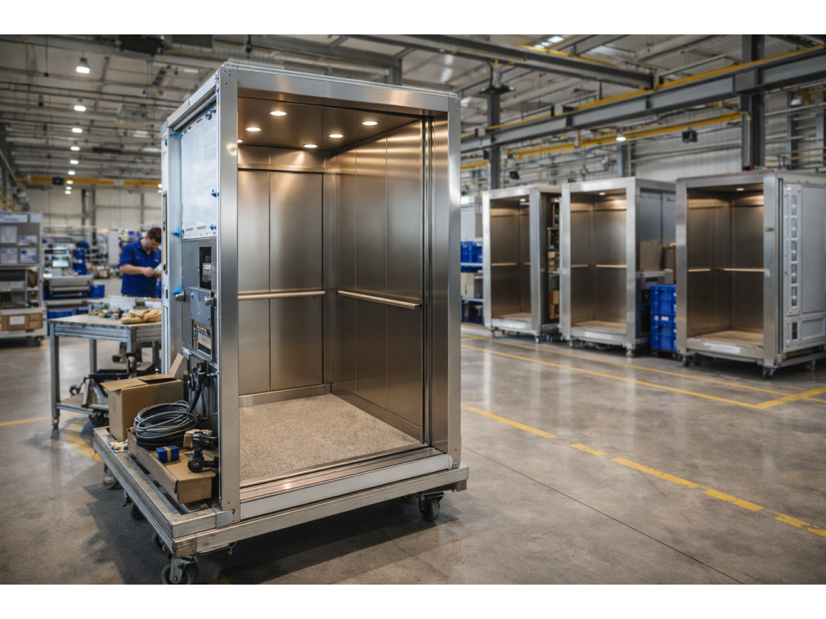
Thin enclosure panels often require internal threads without welding or rear-side access.
Rivet nuts can provide attachment points for:
Brackets
Cable-management components
Covers
Electronics
Grounding-related hardware
Service components
For telecommunications equipment, the engineer should also consider material compatibility, electrical requirements and corrosion environment.
The product name may be similar, but the engineering requirements can be different.
Automotive applications may emphasize:
High-volume assembly
Consistent installation
Vibration
Corrosion
Packaging
Serviceability
Automated tooling
Traceability requirements
Industrial equipment may place greater emphasis on:
Custom geometry
Lower-volume production
Maintenance
Special materials
Different environmental conditions
The supplier should therefore evaluate the application rather than simply match the product name.
One of the most useful distinctions for engineers is that head size and mechanical strength are not interchangeable.
A larger flange changes the interface with the parent sheet.
It does not automatically increase:
Thread strength
Body tensile strength
Torque-out resistance
Pull-out resistance
Fatigue resistance
Each characteristic should be evaluated separately.
The anti-rotation behavior of a rivet nut is created by the interaction between:
Fastener body + mounting hole + parent material + installation condition.
This means that changing the panel material or hole diameter can change the result even when the rivet nut itself remains unchanged.
This is why application-specific validation is more useful than relying only on catalog descriptions.
Procurement teams sometimes request a rivet nut using only:
“Thread + length.”
That information may be insufficient.
A better RFQ identifies:
Thread
Minimum stack thickness
Maximum stack thickness
Hole diameter
Parent material
Head geometry
Body geometry
Material
Finish
Installation method
This creates a much clearer sourcing requirement.
A small change in hole geometry can change the interaction between the insert and the parent sheet.
Depending on the design, an unsuitable hole can increase the risk of:
Rotation
Local deformation
Poor installation
Reduced retention
Inconsistent assembly
The hole should therefore be included on the engineering drawing whenever possible.
Instead of asking only:
“Which rivet nut is strongest?”
The engineer should ask:
“What failure mode must the joint prevent?”
If the concern is pull-through, flange and sheet interaction become important.
If the concern is spin-out, body geometry and hole interaction become important.
If the concern is corrosion, material and surface treatment become important.
If the concern is sealing, the complete enclosure interface must be evaluated.
This approach produces a more efficient engineering selection process.
A practical selection sequence is:
Step 1: Identify the application.
Step 2: Identify the parent material.
Step 3: Measure the actual sheet or stack thickness.
Step 4: Define the mounting-hole diameter and tolerance.
Step 5: Select the required thread.
Step 6: Define the grip range.
Step 7: Determine whether a standard or large-cap head is required.
Step 8: Determine whether anti-rotation geometry is required.
Step 9: Select open-end or closed-end construction.
Step 10: Select material and surface treatment.
Step 11: Define the mating screw.
Step 12: Define installation tooling and process.
Step 13: Validate the complete joint.
A production drawing should ideally define the characteristics that matter to the application.
Depending on the project, this may include:
Thread specification
Thread tolerance
Overall length
Head diameter
Head thickness
Body diameter
Body geometry
Grip range
Mounting-hole requirement
Material
Surface treatment
Installation requirements
Inspection requirements
A clear drawing reduces ambiguity between engineering, procurement and the supplier.
Procurement teams can use the following checklist when requesting quotations:
Part number
Drawing revision
Thread
Quantity
Annual volume
Material
Surface finish
Head style
Head diameter
Body style
Grip range
Hole diameter
Parent material
Application
Installation method
Packaging requirements
Inspection requirements
Documentation requirements
Delivery location
This information makes supplier comparison more meaningful than comparing unit prices alone.
Supplier-development teams should ask:
Can the supplier manufacture the specified geometry?
Can the supplier control the critical dimensions?
Can the supplier work from a customer drawing?
Can the supplier provide material and inspection documentation when required?
Can the supplier support application-specific samples?
Can the supplier identify risks related to hole, grip and installation?
Can the supplier distinguish product capability from customer validation requirements?
These questions help separate product trading from engineering-oriented supply.
Quality requirements should be defined according to the drawing and purchase specification.
Potential inspection items include:
Thread dimensions
Head diameter
Head thickness
Overall length
Body dimensions
Hole-interface dimensions
Surface condition
Material identification
Coating or finish
Visual appearance
Additional functional tests should be defined when the application requires them.
Material documentation should correspond to the actual material requirement.
For example, ASTM A493 covers stainless steel wire and wire rod intended for cold heading or cold forging applications. It should not be presented as a generic finished rivet-nut product standard.
Where a customer requires material certificates, the required document type should be specified in the purchasing documentation.
Automotive rivet nuts do not become compliant simply because a supplier lists a collection of unrelated standards.
The correct approach is to identify the actual scope of each standard.
For stainless steel fasteners, relevant ISO 3506 requirements may apply to particular mating fastener types, while material specifications such as ASTM A493 may apply to raw material used in manufacturing.
For the rivet nut itself, the final engineering requirement should normally be established through the applicable product specification, customer drawing, supplier specification and agreed validation method.
A long list of standards may look impressive but can create confusion if the standards do not actually govern the purchased component.
For an automotive sourcing project, a short and accurate specification is more useful:
Product geometry + material + finish + thread + grip + hole + functional requirements + inspection requirements.
This gives engineering and procurement a common technical reference.
Automotive assemblies rarely contain only one type of fastener.
Depending on the application, the complete fastening system may include:
Blind rivet nuts
Self-clinching fasteners
Weld nuts
Weld screws
Custom bolts
High-strength bolts
Locking nuts
Stainless steel fasteners
CNC-machined components
Plastic fasteners
For related automotive fastening requirements, see industrial and automotive bolts and nuts.
Modern vehicles increasingly combine metal structures with polymer components.
Plastic fasteners may be useful for:
Cable management
Trim
Lightweight covers
Clips
Spacers
Brackets
Insulation-related components
See the JUXIN FASTENERS automotive plastic fastener solutions when a project combines metal threaded fastening with lightweight polymer components.
Some automotive fastening systems require custom spacers, sleeves, shafts, pins or other machined components around the main fastener.
For projects involving custom stainless components, see stainless steel CNC machining parts.
The objective is to develop the complete assembly rather than treat each component as an isolated commodity.
Where the application requires higher-strength mating hardware, the screw or bolt must be evaluated together with the rivet nut.
A high-strength screw does not automatically make a rivet-nut joint stronger.
The weakest component or interface can still determine the joint performance.
For related requirements, see high-strength bolts and nuts.
For OEM sourcing, the most useful starting point is normally the technical requirement rather than a generic product category.
A supplier should understand:
Application → drawing → parent material → hole → grip → thread → fastener geometry → material → finish → installation → validation → volume.
This sequence reduces the risk of selecting a nominally similar part that does not perform correctly in production.
Prototype approval and production approval should be treated as related but different stages.
During prototype development, the focus may be:
Geometry
Fit
Installation
Initial joint behavior
Assembly access
During production development, additional requirements may include:
Dimensional consistency
Surface finish consistency
Packaging
Batch identification
Inspection
Process control
Supply continuity
The exact quality documentation should be defined by the customer.
Automotive purchasing decisions are influenced by more than piece price.
Important commercial factors can include:
Annual demand
Part complexity
Material cost
Surface treatment
Tooling requirements
Packaging
Inspection requirements
Shipping
Lead-time expectations
Forecast stability
Engineering changes
A supplier quotation becomes more accurate when these requirements are known.
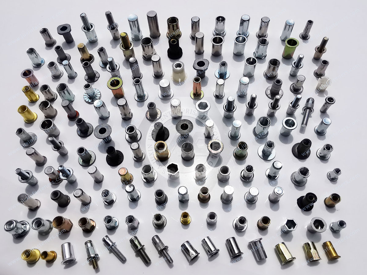
Custom rivet nuts may be appropriate when standard catalog dimensions do not meet the application.
Possible custom features include:
Large flange
Special flange thickness
Knurled body
Semi-hex body
Hex body
Closed-end body
Special grip range
Special thread
Custom length
Custom material
Custom finish
Custom development should be based on an engineering drawing or clearly defined specification.
JUXIN FASTENERS supports B2B customers requiring application-specific fastening components.
For automotive and industrial rivet nut projects, the sourcing process can be based around the customer's actual:
Drawing
Part specification
Application
Parent material
Hole requirement
Thread
Grip range
Material
Finish
Quantity
This approach allows engineering and procurement teams to evaluate the fastener against the actual assembly rather than a generic catalog description.
For the fastest and most accurate technical evaluation, provide:
1. 2D drawing or technical specification
2. 3D model if available
3. Thread requirement
4. Parent sheet material
5. Sheet thickness or stack thickness
6. Mounting-hole diameter
7. Required grip range
8. Head/flange requirement
9. Anti-rotation requirement
10. Open-end or closed-end requirement
11. Material requirement
12. Surface-treatment requirement
13. Mating screw specification
14. Application environment
15. Prototype and annual production quantity
16. Inspection and documentation requirements
This information allows the supplier to understand both the engineering and commercial requirements.
The most important principle is simple:
Do not select an automotive blind rivet nut by thread size alone.
The complete fastening system includes:
Parent sheet + hole + rivet nut body + flange + grip range + installation + mating screw + service environment.
Large-cap designs can help address bearing-area requirements.
Knurled, semi-hex and hex bodies can address rotational resistance when correctly matched to the mounting hole and parent material.
Closed-end designs can address specific enclosure and assembly requirements, but they should not automatically be treated as waterproof or IP-rated components.
Material and surface treatment should be selected according to the actual environment and mating materials.
If you are developing automotive body panels, EV enclosure components, commercial vehicle structures, electrical brackets or industrial sheet-metal assemblies,
JUXIN FASTENERS can review your required rivet nut configuration based on the actual application.
For an OEM or supplier-development RFQ, send the available drawing or specification to:
Email: info@juxinfasteners.com
Please include the required thread, parent material, sheet thickness, hole diameter, grip range, head geometry, anti-rotation requirement, material, surface finish and expected quantity.
JUXIN FASTENERS can then evaluate the required configuration and provide a product proposal based on your specified engineering and sourcing requirements.
 MORE NEWS

Sep. 25, 2026

Sep. 25, 2026

Sep. 25, 2026
Contact Us
Tel.:
+86 020 8621 0320
+86 020 3121 6067
E-mail:
Technical Support:
Navigation
SEND INQUIREY