
Call Us
+86 136 6007 9809
Call Us
+86 136 6007 9809

Jun. 10, 2024
Automotive Grounding Bolts and Screws for Reliable Vehicle Electrical Connections
Automotive grounding bolts and screws are used to secure electrical ground terminals to suitable metallic vehicle structures.
These connections may form part of the low-voltage electrical return path, protective bonding arrangement or equipment grounding system, depending on the vehicle architecture.
In modern automotive manufacturing, a grounding fastener must satisfy both mechanical and electrical requirements.
A bolt may provide adequate mechanical retention while the electrical connection remains unreliable because of paint, oxidation,
contamination, insufficient contact pressure or unsuitable surface treatment.
Conversely, an initially low-resistance connection may deteriorate if the joint loosens or the contact interface corrodes.
For automotive electrical engineers, the central concern is the electrical performance of the completed connection.
For mechanical and manufacturing engineers, the challenge is creating a repeatable joint compatible with the vehicle structure and assembly process.
For production managers, installation consistency, inspection accessibility and rework prevention are important operational considerations.
For procurement and supplier-development teams, the objective is sourcing grounding fasteners that meet the approved drawing and the customer's functional requirements.
JUXIN FASTENERS supplies industrial bolts, hex flange screws, self-tapping screws and drawing-based OEM fastening components for international manufacturing applications.
This guide focuses on automotive grounding fastener design, electrical contact interfaces and OEM production requirements,
rather than treating grounding bolts as ordinary mechanical fasteners.
What Is an Automotive Grounding Bolt?
An automotive grounding bolt is a threaded fastener used in a vehicle electrical grounding or bonding connection.
Depending on the design, it may secure:
A cable terminal or ring lug
A grounding strap
A conductive bracket
An electrical module ground connection
A designated vehicle body grounding point
Common English terms include:
Automotive grounding bolt
Automotive grounding screw
Vehicle ground bolt
Chassis grounding bolt
Automotive earth bolt
Grounding hex flange bolt
The term earth bolt is used in some international markets, while ground bolt and grounding bolt are common in North American technical usage.
Terminology Note
Hitch bolt is generally associated with towing or trailer hitch hardware.
It should not be used as the primary term for an automotive electrical grounding fastener unless it is the specific designation on the customer's drawing.
How Vehicle Grounding Connections Work
Many conventional vehicle electrical systems use metallic body or chassis structures as part of the low-voltage current return path.
A grounding connection may include:
An electrical cable
A crimped terminal
A grounding bolt or screw
A metallic mounting surface
A threaded hole or mating nut
A protective coating or sealing system
The electrical connection depends on the complete current path.
Important Engineering Principle
The presence of a metal bolt does not automatically establish a suitable electrical connection.
The electrical current path must be intentionally designed and verified.
Grounding vs. Electrical Bonding
These terms are related but not always identical.
Grounding
In automotive systems, grounding commonly refers to connecting an electrical circuit or component to the designated vehicle reference or return network.
Electrical Bonding
Bonding refers to establishing electrical continuity between conductive components.
Depending on the application, bonding may be required for:
Electrical safety
Electromagnetic compatibility
Fault-current management
Equipotential connection
Important Distinction
A chassis grounding connection used for a low-voltage return path should not automatically be treated as a qualified high-voltage protective bonding connection.
The electrical architecture and applicable vehicle requirements determine the necessary performance.
Why Automotive Grounding Connections Fail
Grounding problems may result from mechanical, electrical or environmental factors.
Potential contributors include:
Paint or coating at the contact interface
Oxidation
Contamination
Inadequate contact pressure
Fastener loosening
Corrosion
Damaged cable terminals
Incorrect assembly
Unsuitable material combinations
The consequences depend on the affected electrical circuit.
Possible symptoms include:
Intermittent electrical operation
Voltage drop
Unstable sensor signals
Control module faults
Reduced electrical equipment performance
Engineering Recommendation
Diagnose the complete connection and current path rather than assuming the bolt itself is the root cause.
Painted Vehicle Structures and Electrical Contact
Automotive body panels commonly receive protective coatings.
These may include:
Electrophoretic coatings
Primer
Paint
Other corrosion protection layers
Many protective coatings are electrically insulating.
This creates a design challenge when a grounding connection must be established after painting.
Common Engineering Approaches
Depending on the OEM design, a grounding point may use:
A controlled uncoated contact area
A designated conductive interface
A specially designed coating-penetrating fastener
A suitable serrated or contact-forming component
Another validated bonding method
Critical Limitation
Not every grounding bolt can penetrate paint.
Coating penetration depends on the fastener geometry, coating properties, host material and installation process.
Coating-Penetrating Grounding Screws
Certain grounding screws are designed to create conductive contact through a specified surface coating.
Possible design features include:
Specialized thread geometry
Thread-forming or cutting features
Contact-forming surfaces
Application-specific flange geometry
These features may expose or contact the underlying metal during installation.
However, performance must be verified for the intended coating and substrate.
Engineering Consideration
A screw that establishes contact through one coating system may not perform identically with another coating thickness or composition.
Manufacturing Consideration
Coating variation can affect installation torque and electrical contact behavior.
Procurement Consideration
A replacement grounding screw should be qualified against the actual coated component, not only a bare metal test specimen.
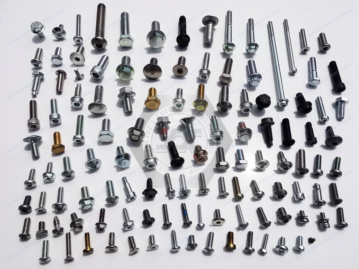
Hex Flange Bolts for Automotive Grounding
Hexagon flange bolts may be used to secure electrical terminals or grounding straps to compatible mounting points.
The integrated flange provides a defined bearing surface.
Potential benefits include:
A larger bearing area than some non-flanged head designs
Convenient installation with suitable tooling
Compatibility with selected automated assembly systems
Reduced need for a separate washer in designs where the flange fulfills that function
Important Distinction
A flange head alone does not guarantee electrical conductivity through a painted surface.
A smooth flange may contact an insulating coating without establishing the intended electrical path.
The contact interface must be designed accordingly.
Flange Geometry and Contact Pressure
The flange diameter and bearing surface influence how installation load is distributed.
A larger flange may reduce local bearing pressure for a given clamp load.
However, the optimal geometry depends on the terminal, host material and contact design.
Engineering Recommendation
Evaluate flange geometry together with the electrical terminal and contact surface.
Serrated Flanges and Contact-Forming Features
Some fastening arrangements use serrations or other contact-forming features.
These may be intended to:
Disrupt surface films
Establish localized metal contact
Influence rotational resistance
However, serrations are not automatically suitable for every grounding connection.
Potential concerns include:
Damage to protective coatings
Corrosion at exposed metal
Damage to soft terminals
Variation in contact performance
Engineering Recommendation
Validate the complete joint rather than assuming that serrations guarantee low electrical resistance.
Thread-Forming Grounding Screws
Thread-forming screws may be used in compatible metallic components.
They form a mating thread during installation.
Important design factors include:
Host material
Pilot hole geometry
Sheet thickness
Screw thread design
Installation torque
Thread engagement
Required clamp load
Important Limitation
Thread-forming capability and electrical grounding capability are separate characteristics.
A thread-forming screw does not automatically establish an approved grounding connection.
Electrical Contact Resistance
Electrical contact resistance is a critical consideration in grounding and bonding connections.
The measured resistance depends on the complete interface.
Relevant factors include:
Contact materials
Surface condition
Contact pressure
Oxidation
Coating
Contamination
Temperature
Environmental exposure
Why Low Resistance Matters
Excessive resistance in a current-carrying connection may create unwanted voltage drop and localized heating.
The acceptable resistance depends on the circuit and applicable OEM requirements.
Engineering Recommendation
Specify the required electrical performance and test method rather than relying on a general claim such as "excellent conductivity."
Voltage Drop and Current-Carrying Connections
For a current-carrying connection, electrical resistance can create voltage drop.
The basic relationship is:
V = I × R
Where:
V is voltage drop
I is current
R is electrical resistance
This relationship illustrates why connection resistance matters.
However, the permissible resistance must be established for the actual electrical system.
Important Limitation
A mechanically secure bolt does not necessarily provide the required current-carrying capability.
The complete conductor, terminal and contact interface must be evaluated.
Grounding Bolt Installation Torque
Installation torque influences the mechanical condition of the joint.
However, the relationship between tightening torque and clamp load depends on:
Thread friction
Bearing-surface friction
Surface finish
Lubrication
Material
Joint stiffness
Why Torque Control Matters
Insufficient tightening may produce inadequate contact pressure.
Excessive tightening may damage:
Threads
Cable terminals
Sheet metal
Contact surfaces
Engineering Recommendation
Use an installation specification validated for the complete grounding connection.
Do not assume that a higher tightening torque always produces better electrical performance.
Grounding Screw Installation into Coated Sheet Metal
For coating-penetrating or thread-forming designs, installation may involve both thread formation and joint tightening.
The torque profile can therefore include several stages.
Potential stages include:
Initial engagement
Coating interaction
Thread formation
Joint seating
Final tightening
Manufacturing Risk
If installation torque is used as the only acceptance criterion, the process may not distinguish between proper seating and excessive resistance during thread formation.
Production Recommendation
Validate the installation method using the actual coated panel and mating terminal.
Contact Interface Design
A grounding connection may use a ring terminal or grounding strap secured under a bolt head or flange.
Important considerations include:
Terminal hole diameter
Terminal thickness
Contact surface area
Terminal material
Surface finish
Stack-up thickness
Required clamp load
Service accessibility
Why Stack-Up Matters
Changes in terminal thickness or washer arrangement can influence screw engagement and joint stiffness.
Engineering Recommendation
Define the complete assembly stack-up on the applicable drawing.
Material Selection for Grounding Bolts
Potential materials include:
Carbon steel
Alloy steel
Selected stainless steels
The correct choice depends on:
Mechanical loading
Corrosion environment
Electrical contact requirements
Surface treatment
Mating materials
Carbon Steel
May be suitable for many automotive grounding fastener designs when appropriately specified and protected.
Alloy Steel
May be considered where additional mechanical requirements justify its use.
Stainless Steel
May be considered for selected corrosion-resistant applications, subject to mechanical and electrical interface requirements.
Important Distinction
The bulk electrical conductivity of the screw material is not the only factor determining connection resistance.
The actual contact interface may govern performance.
Surface Treatment and Corrosion Protection
Potential finishes include:
Zinc plating
Zinc-nickel plating
Black oxide
Zinc-flake coating systems
Other specified protective finishes
Not every finish is suitable for every grounding application.
Engineering Considerations
Electrical contact behavior
Corrosion exposure
Friction characteristics
Coating thickness
Contact surface compatibility
Installation conditions
Why Corrosion Is Particularly Important
A grounding point may initially pass an electrical resistance test but deteriorate after environmental exposure.
The connection should therefore be evaluated for the intended service conditions.
Galvanic Corrosion
Different metals in electrical contact may experience galvanic corrosion when exposed to a suitable electrolyte.
Potential combinations include:
Steel fastener and aluminum structure
Steel fastener and copper terminal
Mixed-metal mounting assemblies
The risk depends on the complete material and environmental system.
Engineering Recommendation
Review galvanic compatibility and protective measures for the complete joint.
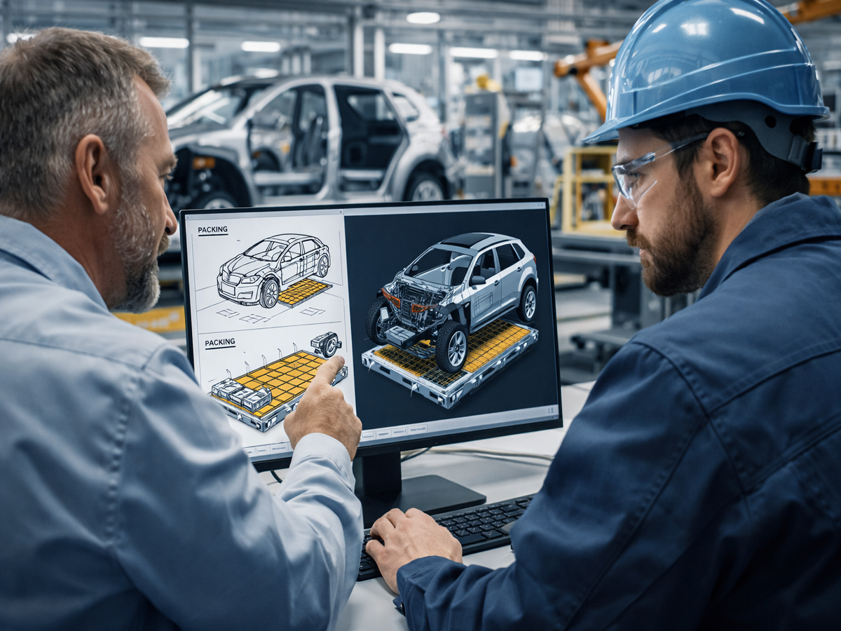
Vibration and Grounding Joint Reliability
Automotive grounding connections may experience vibration and thermal cycling.
Potential failure mechanisms include:
Loss of preload
Relative movement
Contact fretting
Corrosion
Thread loosening
Important Distinction
Electrical contact stability and mechanical loosening resistance are related but separate performance requirements.
A locking feature may help resist unwanted rotation, but it does not automatically maintain the required electrical contact resistance.
Joint Design Recommendation
Evaluate both mechanical retention and electrical continuity under the intended service conditions.
Grounding Fastener Applications in Conventional Vehicles
Potential applications include:
Chassis grounding points
Engine grounding straps
Electrical module ground connections
Body grounding connections
Auxiliary electrical equipment
Each application has different current, environmental and mechanical requirements.
Engine Grounding
Engine grounding connections may experience vibration and temperature variation.
Body Grounding
Body grounding connections may involve coated sheet metal and corrosion protection systems.
Electronic Modules
Electronic module grounding may require attention to electrical noise, contact resistance and installation repeatability.
Important Engineering Principle
Grounding fastener selection must follow the electrical system design.
Grounding and Bonding in Electric Vehicles
Electric vehicles introduce additional electrical safety considerations.
Potential applications include:
Low-voltage chassis grounding
Electrical module grounding
Conductive enclosure bonding
Battery enclosure bonding points
Power electronics equipment mounting
Critical Safety Distinction
A low-voltage grounding connection is not automatically suitable for high-voltage protective bonding.
High-voltage vehicle systems may require specific continuity, fault-current and electrical safety validation.
The appropriate requirements depend on the vehicle architecture and applicable standards.
ISO 6469-3 provides relevant electrical safety requirements for electrically propelled road vehicles.
Its applicability must be assessed according to the vehicle and system.
Battery Enclosure Grounding
Battery enclosures may include designated conductive bonding points.
These connections must be designed in coordination with:
Enclosure material
Protective coatings
Electrical safety requirements
Mechanical loading
Corrosion exposure
Inspection access
Important Limitation
A generic grounding bolt should not be assumed suitable for a battery enclosure protective bonding connection without project-specific qualification.
Electrical Cabinets and Industrial Equipment
Grounding bolts and screws may also be used in suitable industrial electrical assemblies.
Examples include:
Electrical cabinets
Power distribution enclosures
Industrial controllers
HVAC control systems
Machinery electrical housings
Robotics equipment
The applicable electrical safety requirements depend on the equipment and market.
Rail and Aerospace Applications
Rail and aerospace electrical bonding systems may have additional material, testing and approval requirements.
General automotive grounding fasteners should not be represented as qualified for these applications without the necessary project-specific evidence.
Automotive Grounding Fastener Quality Control
Incoming fastener inspection may include:
Thread dimensions
Head and flange geometry
Screw length
Material specification
Surface finish
Visual condition
However, these checks do not establish electrical performance of the installed grounding joint.
Functional Grounding Connection Validation
Depending on the application, validation may include:
Electrical resistance measurement
Voltage-drop evaluation
Mechanical attachment testing
Vibration testing
Environmental exposure
Corrosion testing
Post-exposure electrical verification
The required methods and acceptance criteria should be defined by the OEM or system designer.
Important Quality Principle
A fastener can pass dimensional inspection while the completed grounding connection fails its electrical performance requirement.
Common Grounding Connection Problems
| Problem | Potential cause | Engineering review |
|---|---|---|
| High contact resistance | Insulating coating or contamination | Contact interface |
| Intermittent electrical operation | Contact movement or poor connection | Mechanical and electrical condition |
| Excessive installation torque | Thread-forming or friction variation | Screw and hole compatibility |
| Terminal damage | Excessive clamp load | Installation specification |
| Corrosion near contact | Exposed metal or mixed materials | Corrosion protection |
| Grounding point loosens | Joint design or preload loss | Mechanical retention |
| Electrical performance varies by lot | Coating or surface variation | Incoming and process control |
| Replacement screw fails | Different geometry or coating | Functional equivalence |
| Post-aging resistance increases | Environmental degradation | Aging and corrosion validation |
Production-Line Installation and Inspection
For high-volume automotive manufacturing, grounding fastener installation should be repeatable.
Production considerations may include:
Fastener feeding
Terminal positioning
Coating condition
Installation torque
Screw seating
Electrical testing
Traceability where required
Production Manager Considerations
A grounding fastener that requires frequent installation adjustment may increase cycle time and rework.
Manufacturing Recommendation
Where electrical performance is critical, consider a validated electrical inspection method in addition to mechanical assembly monitoring.
Supplier Qualification for Automotive Grounding Bolts
A supplier qualification process should distinguish fastener conformance from completed electrical connection performance.
Drawing Conformance
Confirm:
Thread
Head geometry
Flange dimensions
Length
Material
Surface finish
Functional Requirements
Confirm:
Intended contact mechanism
Mating surface
Electrical performance criteria
Installation requirements
Environmental exposure
Production Compatibility
Review:
Feeding system
Installation tools
Pilot hole or mating thread
Coating condition
Assembly cycle
Quality Documentation
Define:
Inspection requirements
Material documentation
Lot identification
Sample approval
Customer-specific qualification requirements
Commercial Requirements
Review:
MOQ
Annual forecast
Packaging
Lead time
Delivery conditions
Second-Source Qualification
A replacement grounding bolt should not be approved solely because its nominal dimensions match.
Functional equivalence may depend on:
Contact-forming geometry
Coating interaction
Installation torque
Electrical resistance
Corrosion performance
Mating component compatibility
Procurement Principle
A mechanically interchangeable bolt is not automatically an electrically equivalent grounding fastener.
OEM Grounding Bolt RFQ Checklist
For an accurate technical and commercial review, provide:
Fastener Specification
2D drawing or 3D model
Thread designation
Head and flange geometry
Screw length
Material
Surface finish
Electrical Requirements
Grounding or bonding function
Required electrical performance
Current or fault requirements where applicable
Test method and acceptance criteria
Mating Component
Host material
Panel thickness
Coating type and thickness
Hole or mating thread specification
Cable terminal material and geometry
Production Requirements
Installation method
Torque requirements
Assembly equipment
Inspection requirements
Commercial Requirements
Sample quantity
Initial order quantity
Annual forecast
Packaging
Delivery destination
Frequently Asked Questions
What is an automotive grounding bolt?
It is a fastener used to secure a designated electrical ground or bonding connection to a suitable vehicle structure.
Is an automotive hitch bolt the same as a grounding bolt?
Not generally. Hitch bolt usually refers to towing hardware. Grounding bolt is the more appropriate term for electrical grounding applications.
Can a grounding screw penetrate vehicle paint?
Some specialized designs may create conductive contact through specified coatings, but performance must be validated.
Do hex flange bolts automatically provide electrical grounding?
No. The flange geometry alone does not guarantee electrical continuity.
Can grounding screws be installed in coated sheet metal?
Yes, in suitable qualified designs. The screw, coating, substrate and installation process must be compatible.
Does a higher tightening torque improve grounding?
Not necessarily. Excessive torque may damage the terminal or mating thread.
What is the difference between grounding and bonding?
Grounding generally refers to a designated electrical reference or return connection, while bonding establishes electrical continuity between conductive components.
Can automotive grounding bolts be used in EV battery enclosures?
Only where the fastener and complete connection meet the applicable project-specific requirements.
What should purchasing check when qualifying a grounding bolt supplier?
Drawing conformance, contact mechanism, material, coating, installation compatibility and electrical validation requirements.
Can JUXIN FASTENERS review custom grounding bolt drawings?
Yes. Customers can submit drawings and electrical connection requirements for technical feasibility and quotation review.
JUXIN FASTENERS: Automotive Grounding Bolts and Custom OEM Fasteners
JUXIN FASTENERS supplies industrial bolts, screws and drawing-based fastening components for international OEM manufacturing.
Relevant products include:
Automotive grounding bolts
Hex flange screws
Grounding screws
Self-tapping screws
Custom drawing-based bolts
Related industrial fastening components
The appropriate fastener geometry, material, surface finish and electrical contact requirements must be confirmed for each application.
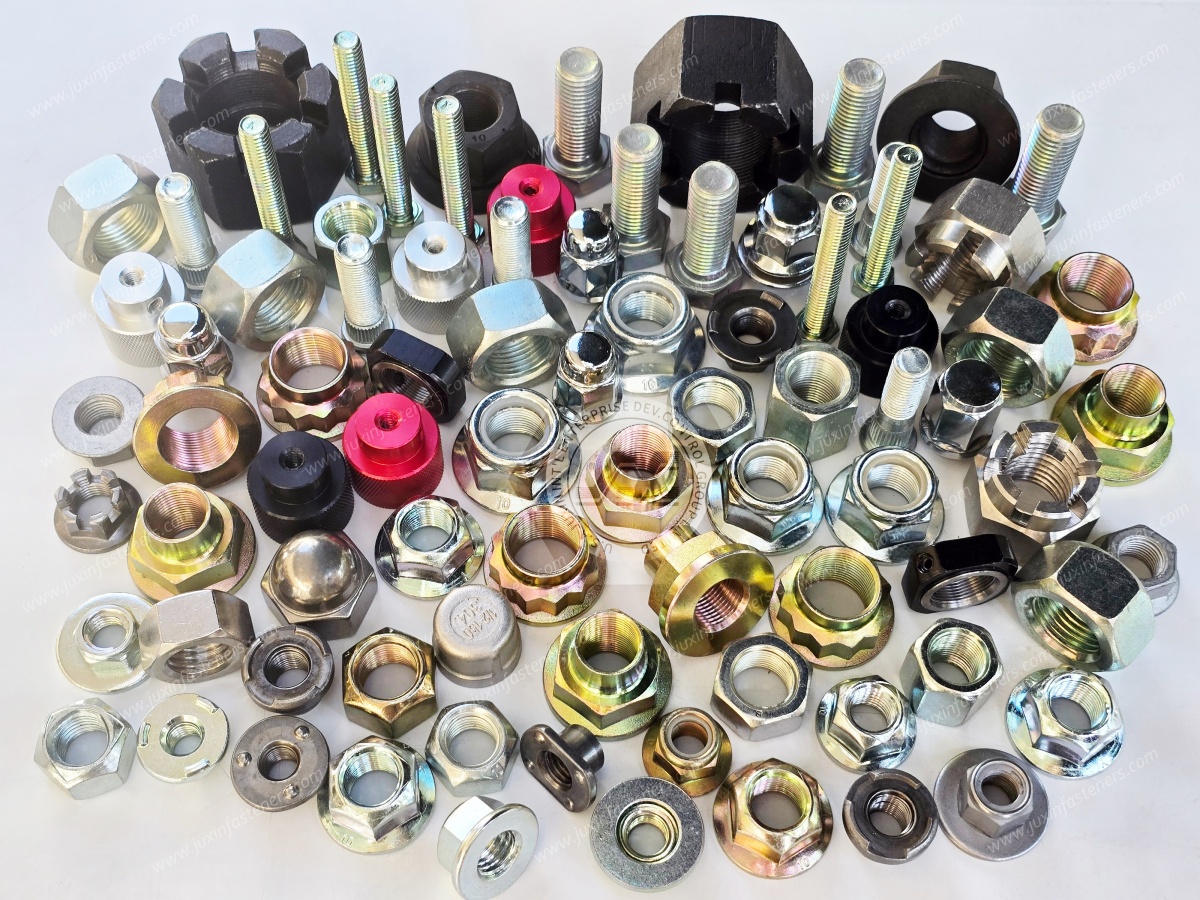
Request an Automotive Grounding Bolt Drawing Review and RFQ
If you are sourcing grounding bolts for vehicle body connections, developing a coated sheet metal grounding point or qualifying an alternative grounding fastener supplier, contact JUXIN FASTENERS.
For efficient technical review, provide:
Fastener drawing + mating material and coating + electrical performance requirements + installation method + annual purchasing volume
JUXIN FASTENERS can review the submitted requirements and discuss suitable standard or drawing-based fastening options.
Company: JUXIN FASTENERS
Website: https://www.juxinfasteners.com/
Email: info@juxinfasteners.com
Send your automotive grounding bolt drawings and OEM RFQ requirements to JUXIN FASTENERS for technical evaluation and quotation.
Contact Us
Tel.:
+86 020 8621 0320
+86 020 3121 6067
E-mail:
Technical Support:
Navigation
SEND INQUIREY



