
Call Us
+86 136 6007 9809
Call Us
+86 136 6007 9809

Aug. 26, 2023
Blind rivet nuts, also known as rivet nuts, blind threaded inserts, nutserts, or blind nuts,
provide an internal threaded connection in applications where access to the rear side of the parent material is limited or unavailable.
They are widely considered when engineers need to add a reusable threaded mounting point to thin sheet metal,
formed panels, tubular profiles, hollow structures, electrical enclosures, automotive components,
HVAC equipment, industrial machinery, appliances, and other assemblies where conventional through-bolting or welding is inconvenient.
The important engineering point is that a blind rivet nut should not be evaluated as an isolated fastener.
The final joint depends on the interaction between the rivet nut, mounting hole, parent material, grip range, installation process, mating screw, assembly load, and service environment.
For that reason, product selection should begin with the application rather than simply selecting a thread size from a catalog.
JUXIN FASTENERS supplies blind rivet nut solutions for OEM and industrial applications where engineers and procurement teams need to define thread type,
body geometry, grip range, material, surface treatment, head configuration, installation method, and application requirements.
This guide explains the engineering mechanics, material selection principles, anti-rotation options, installation considerations,
industrial applications, and procurement information needed to develop a controlled blind rivet nut specification.

A blind rivet nut is a tubular threaded fastener designed to create an internal thread in a component that can normally be accessed from only one side.
The fastener typically contains:
An internal threaded section
A flange or head
A deformable body section
A blind-side deformation zone
An external body geometry selected for the parent material and application
During installation, a suitable tool engages the internal thread and causes the deformable portion of the rivet nut body to form against the rear side of the panel.
The result is a mechanically retained threaded insert.
The exact deformation mechanism depends on the rivet nut design, material, dimensions, grip range, installation tooling, and application.
Blind rivet nuts solve a specific manufacturing problem: creating an internal threaded connection without requiring access to both sides of the workpiece.
Typical reasons for selecting them include:
One-sided installation
Limited rear-side access
Thin sheet-metal construction
Hollow structures
Tubular profiles
Enclosures
Serviceable threaded connections
Replacement of certain welded threaded components
Integration into formed sheet-metal assemblies
Simplification of assembly access
They can also allow a manufacturer to separate the creation of the threaded mounting point from the joining of the final component.
Direct tapping requires sufficient parent-material thickness and suitable material properties to create and retain the required thread.
In thin sheet metal, the available thread engagement may be limited.
A blind rivet nut moves the internal thread into a separate fastener rather than relying entirely on the thickness of the parent sheet.
This can be useful where:
The sheet is relatively thin
The parent material is difficult to tap
A reusable internal thread is required
Rear-side access is restricted
The design requires a standardized threaded mounting point
However, a rivet nut does not automatically provide a stronger joint than a tapped hole.
The actual joint capability depends on the complete assembly.
Weld nuts can provide a robust threaded connection, but welding introduces a thermal joining process.
Depending on the component and manufacturing process, welding may require consideration of:
Heat input
Surface condition
Distortion
Weld spatter
Post-processing
Coating condition
Access for welding equipment
Fixture design
Blind rivet nuts provide a mechanical installation alternative where welding is undesirable or impractical.
They are particularly relevant when the panel has already been coated, formed, painted, or assembled into a structure where welding access is restricted.
The correct choice depends on the complete manufacturing process rather than on the fastener alone.
Through-bolting generally requires access to both sides of the joint.
That can be straightforward on an open frame but difficult inside:
Tubes
Box sections
Enclosures
Automotive body structures
HVAC housings
Electrical cabinets
Machinery frames
A blind rivet nut allows the mating screw to be installed from the accessible side.
This can reduce assembly-access requirements.
Single-sided installation is one of the defining characteristics of blind rivet nuts.
The operator can normally install the insert from the accessible side while the deforming section forms behind the parent material.
This is especially useful where the rear side is:
Completely enclosed
Physically inaccessible
Too narrow for a hand tool
Occupied by another component
Located inside a hollow profile
The exact tooling method should be selected according to the product design and production environment.
The general installation sequence is:
Prepare the mounting hole.
Confirm hole diameter and condition.
Select the appropriate rivet nut.
Engage the installation mandrel or tool interface.
Position the rivet nut in the hole.
Operate the installation tool.
Form the blind-side deformation.
Confirm seating and installation condition.
Install the mating screw.
The deformation should create the intended mechanical retention without unnecessarily damaging the parent material.
The installation mandrel transfers the installation motion into the rivet nut.
The mandrel must be compatible with:
Internal thread
Fastener dimensions
Installation tool
Rivet nut design
Production method
The mandrel is not simply a generic rod.
Its engagement with the internal thread is part of the installation system.
Improper engagement can damage threads or affect installation consistency.
Blind rivet nuts depend on controlled deformation of the body.
The installation process changes the geometry of the blind section so that it bears against the rear surface of the parent material.
The engineering objective is to obtain sufficient retention while avoiding excessive deformation.
Too little deformation can result in insufficient retention.
Excessive deformation can damage the insert, distort the panel, or create an inconsistent joint.
Therefore, installation settings should be established for the actual rivet nut, material, thickness, hole condition, and tooling system.
One of the most important engineering principles is that the rivet nut and panel must be treated as one mechanical system.
The relevant variables include:
Rivet nut material
Rivet nut geometry
Panel material
Panel thickness
Hole diameter
Hole tolerance
Grip range
Installation condition
Load direction
Mating screw
Assembly torque
Environmental exposure
A rivet nut that performs appropriately in one sheet material may behave differently in another.
The mounting hole is a functional part of the joint.
The hole must be compatible with the selected rivet nut design.
Important variables include:
Nominal hole diameter
Actual measured diameter
Hole tolerance
Roundness
Burr condition
Edge deformation
Coating thickness
Hole-making process
The correct hole dimension should come from the applicable product drawing or controlled supplier specification.
A hole that is too small can interfere with installation.
A hole that is too large can reduce the intended interface between the rivet nut body and parent material.
Therefore, the nominal hole size alone is not enough.
OEM drawings should control the hole dimension and manufacturing tolerance.
Hole quality becomes particularly important for anti-rotation and thin-sheet applications.
Engineers should consider:
Drilled holes
Punched holes
Laser-cut holes
Stamped holes
Deburred holes
Coated holes
Different manufacturing processes can create different edge conditions.
A production validation should therefore use representative production holes rather than relying only on ideal laboratory samples.
Burrs can interfere with seating and alter the interface between the rivet nut and panel.
In some applications, excessive burrs may also affect:
Installation consistency
Flange seating
Hole size
Rotation resistance
Panel damage
The hole preparation process should therefore be part of the joint specification.
Grip range describes the parent-material thickness or assembly thickness that a particular rivet nut configuration is designed to accommodate.
It is one of the most important selection parameters.
Grip range should not be selected from the nominal sheet thickness alone.
The actual stack-up may include:
One sheet
Multiple sheets
Coatings
Washers
Brackets
Spacers
Laminated materials
A common engineering mistake is to treat grip range as identical to the thickness of one sheet.
For a multi-layer assembly, the effective stack-up may be different from the thickness of the primary panel.
The correct selection therefore requires the actual assembly condition.
If the selected rivet nut is outside its intended grip range, deformation may not occur as intended.
Potential consequences include:
Poor seating
Inconsistent retention
Panel deformation
Incomplete deformation
Excessive deformation
Variable installation results
For OEM applications, grip range should be specified on the engineering drawing.
Thread size should be selected according to the mating component and joint requirements.
Common industrial configurations include metric and inch threads.
The specification should define:
Nominal thread
Pitch
Thread class where applicable
Thread length
Mating screw
Required assembly condition
JUXIN FASTENERS can review the complete fastener specification rather than treating thread size as the only selection parameter.
The rivet nut and mating screw must be considered together.
Relevant factors include:
Thread form
Thread diameter
Pitch
Thread engagement
Screw material
Screw coating
Assembly torque
Service environment
A high-strength mating screw does not automatically create a high-strength rivet-nut joint.
The parent panel and rivet nut interface may remain the governing failure location.
Thread engagement should be evaluated according to the actual insert geometry and mating screw.
The objective is to establish an appropriate threaded connection without:
Bottoming the screw
Interfering with the blind end
Reducing usable thread
Damaging the insert
Creating unnecessary installation depth
For blind or closed-end configurations, screw length requires particular attention.
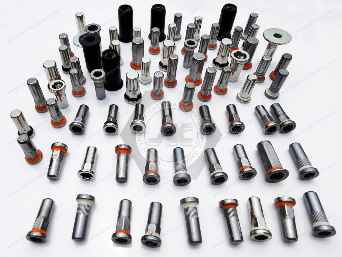
Open-end rivet nuts have an open internal passage through the body.
They are commonly used where the application does not require a closed end.
Potential advantages include:
Broad application flexibility
Conventional threaded mounting
Availability in multiple body configurations
Suitability for many general industrial assemblies
The choice should still be based on the complete application.
Closed-end rivet nuts provide a closed distal end.
They can be considered when the design needs separation between the internal thread and the rear side of the component.
Typical applications may include:
Enclosures
Electrical housings
Battery-related structures
Equipment exposed to contamination
Assemblies where a closed threaded insert architecture is preferred
Closed-end construction alone does not establish a particular IP rating or waterproof performance.
Sealing blind rivet nuts incorporate a design intended to reduce the path for fluid or environmental ingress around the fastener interface.
They can be useful in applications where environmental sealing is important.
However, sealing performance must be evaluated at the assembly level.
Relevant variables include:
Fastener design
Panel material
Hole geometry
Mating screw
Seal interface
Installation condition
Enclosure design
A sealing rivet nut should therefore not automatically be described as an IP-rated component.
IP classifications such as those defined under IEC 60529 relate to the protection provided by an enclosure or equipment assembly.
Therefore, an OEM requiring a particular IP level should validate:
Enclosure construction
Panel joints
Fastener interfaces
Gaskets
Sealing washers
Cable entries
Service openings
Rivet nut interfaces
A closed-end or sealing rivet nut can contribute to the design but does not independently establish the final enclosure rating.
The head or flange controls how the rivet nut interfaces with the front surface of the panel.
Important considerations include:
Head diameter
Head thickness
Head profile
Bearing area
Flush requirements
Counterbore requirements
Visual requirements
The correct geometry depends on the parent panel and assembly design.
Flat-head rivet nuts provide a bearing surface against the front side of the panel.
They are useful where a conventional flange interface is acceptable.
The engineer should evaluate:
Available surface area
Panel thickness
Edge distance
Adjacent components
Cosmetic requirements
Countersunk designs can be used where a reduced surface projection is required.
However, the countersink geometry must be compatible with the parent panel.
The engineer should specify:
Countersink angle
Countersink diameter
Head geometry
Panel thickness
Flushness requirement
Countersinking a thin sheet can itself influence the remaining material around the hole.
Knurled or ribbed body designs introduce additional mechanical interaction between the insert and mounting hole.
They can be considered where rotation resistance is an important design requirement.
The effectiveness depends on:
Knurl geometry
Hole size
Parent material
Panel thickness
Installation condition
Knurling should not be treated as a universal guarantee against spin-out.
Hex and semi-hex configurations can provide a geometric anti-rotation interface when the mounting hole is designed appropriately.
This can be valuable in applications where assembly torque or repeated service could otherwise encourage rotation.
The hole geometry must match the body geometry.
Anti-rotation performance is not determined by the rivet nut body alone.
It depends on the interface between:
Body geometry
Hole geometry
Parent material
Installation deformation
Assembly torque
Service loads
This is why a product description such as “anti-rotation rivet nut” should still be supported by application-specific validation.
Pull-out describes a failure mode where the rivet nut is displaced from the parent material under axial loading.
Possible governing mechanisms include:
Insert deformation
Panel deformation
Pull-through
Local material failure
Insufficient installation
Inappropriate grip selection
The measured result belongs to a specific fastener-panel combination.
Pull-through can occur when the parent material around the installed insert fails before the insert itself reaches its own material limit.
This is especially relevant in thin sheet.
The parent panel therefore needs to be evaluated together with the rivet nut.
Torque-out refers to rotational failure of the insert or its interface with the parent material under applied torque.
It is different from axial pull-out.
An application requiring high assembly torque should therefore specify and validate torque-related behavior separately.
Spin-out occurs when the rivet nut rotates within the mounting hole instead of maintaining the required fixed orientation.
Potential contributors include:
Oversized hole
Weak parent material
Insufficient anti-rotation geometry
Installation problems
Excessive assembly torque
Poor interface control
Pull-out and torque-out should not be treated as interchangeable performance measurements.
A rivet nut may resist one load mode differently from another.
OEM validation should therefore define the actual load cases relevant to the application.
Some applications introduce transverse loading across the rivet nut and panel.
Shear behavior depends on:
Fastener geometry
Panel thickness
Hole geometry
Load direction
Mating component
Joint configuration
A rivet nut selected only from an axial retention requirement may not be sufficient for a joint dominated by shear.
Offset brackets can introduce bending moments into the fastener system.
This is common in:
Equipment brackets
Electrical enclosures
Automotive mounting systems
HVAC assemblies
Machinery panels
The joint should therefore be evaluated based on the actual bracket geometry rather than simply the nominal screw diameter.
Thin sheet metal is one of the primary application areas for blind rivet nuts.
They can provide an internal thread without requiring a thick parent material.
Typical materials include:
Carbon steel
Stainless steel
Aluminum
Certain coated sheet-metal systems
The correct insert geometry depends on the panel and application.
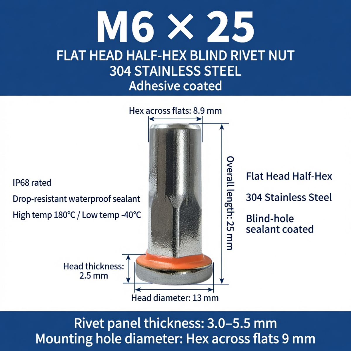
Automotive applications may use blind rivet nuts in:
Body panels
Interior structures
Brackets
Trim systems
Underbody components
Equipment mounting
Serviceable assemblies
Automotive applications can involve vibration, thermal cycling, corrosion exposure, and high production volumes.
The fastener specification should reflect the actual vehicle assembly.
Electric vehicle structures can involve aluminum and steel panels, enclosure assemblies, brackets, covers, and service components.
Blind rivet nuts may provide threaded attachment points where rear-side access is limited.
Relevant considerations include:
Panel material
Panel thickness
Stack-up
Sealing requirements
Corrosion compatibility
Assembly torque
Thermal cycling
Service access
For battery enclosure applications, sealing must be validated as part of the complete enclosure system.
JUXIN FASTENERS also provides dedicated sealing blind rivet nut solutions for EV battery enclosures.
Electrical cabinets and equipment housings frequently require internal mounting points for:
Brackets
Covers
Control components
Cable-management hardware
Internal assemblies
Blind rivet nuts can be useful where the rear side of the panel cannot be reached after enclosure formation.
HVAC housings may contain thin sheet-metal panels, brackets, service components, insulation interfaces, and confined structures.
Blind rivet nuts can provide threaded mounting points without requiring conventional rear-side nut installation.
The engineering review should include:
Sheet material
Coating
Environment
Condensation exposure
Assembly access
Service requirements
Industrial equipment can use blind rivet nuts for:
Guard panels
Covers
Brackets
Electrical components
Access panels
Internal mounting systems
The correct selection depends on the load and service conditions.
Appliance housings often use formed sheet metal where welding, tapping, or through-bolting may introduce manufacturing constraints.
Blind rivet nuts can provide repeatable threaded attachment points for:
Internal brackets
Control assemblies
Panels
Covers
Service components
The interface should be evaluated for appearance, corrosion, assembly torque, and panel deformation.
Tubular and hollow structures are particularly suited to one-sided fastening.
Examples include:
Frames
Equipment profiles
Vehicle structures
Machinery housings
Enclosed brackets
The main advantage is access.
The rear side of the tube does not need to be physically reached during normal installation.
Specialized blind fastening systems can also be considered for composite and non-metallic panels.
However, composite materials should not be treated as mechanically equivalent to sheet metal.
Important variables include:
Laminate construction
Core structure
Local reinforcement
Panel crushing
Hole quality
Load distribution
For softer substrates, specialized expandable architectures such as jack nuts may be more appropriate.
See the Jack Blind Rivet Nut engineering guide.
Carbon steel rivet nuts can be considered where mechanical requirements, cost, and environmental conditions support steel construction.
Surface treatment may be required depending on the application.
Possible considerations include:
Zinc-based coatings
Zinc-nickel systems
Other specified finishes
Coating thickness
Hydrogen-related process considerations where applicable
Galvanic compatibility
The final coating should be specified according to the actual application.
Stainless steel can be selected where corrosion resistance or material compatibility is important.
Common engineering discussions may include stainless grades and application-specific material requirements.
ISO 3506 covers certain stainless steel fastener categories, but its scope is product-specific and should not be automatically applied to every
blind rivet nut design. ISO 3506-1, for example, addresses bolts, screws and studs, while ISO 3506-6 provides general selection information for stainless steels and nickel alloys used for fasteners.
For a rivet nut, the applicable material and product specification should therefore be defined on the drawing or purchase specification.
Aluminum rivet nuts can be considered where low mass and material compatibility are important.
However, lower density does not automatically mean a lighter complete joint.
The engineer should consider:
Insert mass
Panel material
Joint loads
Corrosion compatibility
Thread requirements
Installation behavior
Service environment
For dedicated aluminum closed-end applications, see the aluminum closed-end blind rivet nut solution.
Material selection should consider both the insert and the parent material.
Relevant questions include:
What is the panel material?
What is the fastener material?
Is the environment corrosive?
Is galvanic coupling possible?
What is the service temperature?
What is the assembly torque?
Is weight reduction important?
Is the joint structural or primarily mounting-related?
Material selection should never be reduced to “steel versus stainless versus aluminum.”
When dissimilar metals are joined in an electrically conductive and environmentally suitable electrolyte, galvanic corrosion can become a design consideration.
Potential combinations include:
Aluminum panel + steel insert
Aluminum panel + stainless insert
Steel panel + stainless insert
The actual risk depends on the materials, surface conditions, environment, electrical contact, and exposure.
The joint should therefore be reviewed as a complete material system.
Surface treatment can influence:
Corrosion behavior
Appearance
Friction
Assembly characteristics
Electrical contact
Environmental compatibility
Potential finishes should be specified rather than assumed.
For JUXIN FASTENERS OEM programs, the required finish should be defined by the customer drawing or purchase specification.
Corrosion test results should be interpreted carefully.
A laboratory corrosion test is not automatically equivalent to a guaranteed field-service lifetime.
When a customer requires a specific corrosion test method, the RFQ should identify:
Test method
Specimen configuration
Coating system
Acceptance criteria
Test duration
Reporting requirements
ASTM B117, for example, is a laboratory salt-spray test method and should not be presented as a direct prediction of service life.
Coating thickness can influence fit and installation.
Potential effects include:
Effective hole size
Body clearance
Thread condition
Installation friction
Electrical contact
Surface appearance
Therefore, coated panels and finished production components should be included in validation.
Installation stroke is the amount of tool movement required to achieve the intended deformation.
It is product-specific.
The correct setting depends on:
Rivet nut geometry
Material
Grip range
Parent material
Tool
Installation method
Generic stroke values should not be applied across different rivet nut designs.
Installation force is another product- and application-specific parameter.
It can be influenced by:
Material
Wall thickness
Body geometry
Grip range
Mandrel design
Tool configuration
Production settings should be established using the actual approved fastener and assembly.
Blind rivet nut tools may include:
Manual tools
Hand-operated setting tools
Pneumatic systems
Battery-powered systems
Production-line installation equipment
The correct tool depends on production volume, access, insert design, and process requirements.
The tool should be compatible with the specific fastener rather than selected only by thread size.
Over-installation can cause unnecessary deformation.
Potential consequences include:
Panel damage
Insert distortion
Thread damage
Inconsistent installation
Reduced dimensional control
The production process should therefore define appropriate installation conditions.
Under-installation can result in insufficient deformation and inadequate retention.
Potential causes include:
Incorrect tool setting
Wrong grip range
Incomplete stroke
Tool malfunction
Incorrect fastener selection
Installation verification should be part of production quality control.
Thin sheet can deform during installation or service.
The engineer should consider:
Panel thickness
Material strength
Hole proximity to edges
Hole proximity to bends
Local reinforcement
Installation load
The insert may remain intact while the panel becomes the governing failure point.
Vibration can influence the complete threaded joint.
Relevant factors include:
Mating screw
Assembly torque
Joint preload
Insert retention
Panel stiffness
Load direction
Joint movement
A blind rivet nut should not automatically be described as vibration-proof.
The complete joint needs to be evaluated for the expected service environment.
Automotive, EV, HVAC, industrial, and outdoor equipment can experience temperature changes.
Different materials may expand and contract at different rates.
This can affect:
Joint interfaces
Panel stress
Fastener preload
Coating behavior
Sealing interfaces
Thermal-cycle validation should use the actual material combination and assembly configuration.
Moisture exposure can affect the fastener system through:
Corrosion
Galvanic interaction
Coating degradation
Contamination
Sealing interfaces
For outdoor and enclosure applications, environmental requirements should be defined during the engineering stage.
When blind rivet nuts are installed into plastic or composite structures, long-term deformation can become important.
Plastic is not one single engineering material.
PA6, PA66, POM, PP, PC, PVDF, PEEK, and reinforced polymers can behave differently under:
Load
Temperature
Moisture
Chemical exposure
Time
Specialized threaded insert solutions should therefore be selected according to the actual polymer and loading condition.
Grip range should not be treated as a catalog checkbox.
It affects how the rivet nut deforms and interfaces with the parent structure.
A useful engineering selection process is:
Actual stack-up → grip requirement → rivet nut geometry → installation condition → validation
This is more reliable than selecting a rivet nut based only on thread size.
The hole is often treated as a manufacturing detail.
For blind rivet nuts, it is part of the mechanical interface.
Hole diameter, tolerance, roundness, burrs, and parent material all influence installation and retention.
Therefore, a fastener drawing without a controlled mounting-hole specification may leave an important part of the joint undefined.
In a thin panel, the insert itself may not be the weakest part of the system.
The governing failure may occur through:
Pull-through
Panel tearing
Local deformation
Hole enlargement
Edge failure
This is why supplier data should be interpreted together with the actual parent material.
Axial retention and rotational retention are different engineering problems.
A design that requires high assembly torque needs more than an axial pull-out assessment.
The RFQ should identify the actual load cases.
A high-strength screw can still be installed into a joint whose governing limitation is:
Rivet nut retention
Panel thickness
Hole geometry
Local sheet deformation
Thread engagement
The complete joint should therefore be designed around the weakest relevant interface.
A closed-end rivet nut physically closes the end of the fastener.
That does not automatically make the entire enclosure waterproof.
Water or contaminants can still enter through:
Panel interfaces
Screw interfaces
Gaps
Adjacent joints
Other enclosure openings
Sealing requirements should therefore be validated at assembly level.
Knurling, ribs, hex bodies, and semi-hex bodies can improve mechanical interaction with the panel.
However, their effectiveness depends on the mounting hole and parent material.
The same rivet nut geometry can therefore behave differently in different panels.
A plastic panel cannot be specified simply as “plastic.”
Engineers should identify:
Polymer family
Reinforcement
Thickness
Temperature
Moisture exposure
Long-term loading
Chemical environment
This information can materially change the appropriate threaded insert architecture.
Choosing stainless steel only because the application is “outdoor” may not be sufficient.
The complete material system should be reviewed.
An aluminum panel with a stainless insert, for example, requires a different corrosion assessment from a steel panel with a carbon-steel insert.
A rivet nut specification does not fully define the finished joint.
Installation also matters.
The process should control:
Tool
Mandrel
Stroke
Installation force where applicable
Fastener orientation
Hole condition
Grip range
Operator or machine settings
A practical engineering workflow is:
1. Identify the application.
2. Identify the parent material.
3. Measure actual panel thickness.
4. Determine the complete stack-up.
5. Define the mounting hole.
6. Select the thread.
7. Define grip range.
8. Select head geometry.
9. Select body geometry.
10. Determine whether anti-rotation is required.
11. Determine open-end, closed-end, or sealing configuration.
12. Select material.
13. Select surface treatment.
14. Check mating screw compatibility.
15. Define installation method.
16. Identify load cases.
17. Review environmental conditions.
18. Validate the complete assembly.
A controlled drawing should ideally define:
Part number
Thread
Thread pitch
Head type
Head dimensions
Body geometry
Overall length
Grip range
Material
Surface treatment
Mounting-hole requirement
Applicable dimensional tolerances
Special application requirements
Inspection requirements
The more precisely the joint is defined, the easier it becomes for procurement to compare suppliers accurately.
Procurement teams should request information that allows suppliers to quote the same technical product.
A useful RFQ should include:
Drawing
Thread
Material
Surface treatment
Grip range
Head geometry
Body geometry
Mounting-hole information
Annual volume
Packaging requirements
Inspection requirements
Required documentation
Application description
This reduces the risk of comparing technically different products under the same commercial description.
Supplier development teams should evaluate:
Manufacturing capability
Product understanding
Material control
Dimensional control
Thread inspection
Surface-treatment control
Traceability requirements
Change control
Packaging
Sample validation
Production consistency
Technical communication
The supplier should understand the application rather than simply quote a catalog part.
For OEM programs, material documentation may need to match the customer's specification.
Depending on the project, documentation can include:
Material declarations
Inspection reports
Certificates requested by the customer
Surface-treatment documentation
Dimensional inspection records
Batch identification
The required documentation should be agreed during RFQ and supplier qualification.
Typical dimensional and functional checks may include:
Overall dimensions
Head dimensions
Body dimensions
Thread condition
Hole compatibility
Surface condition
Material verification where specified
Installation condition
The exact inspection plan should reflect the customer drawing and quality requirements.
Internal threads should be checked according to the applicable drawing and thread specification.
Inspection methods can include appropriate gauges or measurement systems selected for the thread type and tolerance.
Thread inspection should confirm that the mating screw can engage correctly without damaging the insert.
Important dimensions can include:
Head diameter
Head thickness
Body diameter
Overall length
Thread dimensions
Grip-related dimensions
Anti-rotation geometry
The critical-to-function dimensions should be identified during product development.
Before production release, the rivet nut should be installed into representative parent material.
Validation should consider:
Actual hole
Actual sheet
Actual grip
Actual tool
Actual installation method
Actual mating screw
This is more meaningful than validating the insert in isolation.
Application validation should reproduce the expected service condition as far as practical.
Depending on the application, this may include:
Axial loading
Torque loading
Shear loading
Vibration
Thermal cycling
Moisture
Corrosion exposure
The test method should be agreed between the customer and supplier.
Production control should focus on the characteristics that influence joint performance.
These can include:
Material
Dimensions
Thread
Body geometry
Surface treatment
Tooling
Installation-related characteristics
Packaging
The exact control plan should be developed according to the customer requirements.
OEM customers should know when a change could affect product performance.
Potential changes may involve:
Material
Surface treatment
Tooling
Manufacturing process
Geometry
Supplier source
Packaging
Formal change-control requirements should be established for production programs.
Packaging should protect the fasteners from:
Contamination
Mechanical damage
Corrosion exposure
Mixing of part numbers
Identification should clearly distinguish:
Part number
Size
Material
Batch where required
Quantity
Customer reference where applicable
Blind rivet nuts can support many industrial sectors, including:
Body panels
Interior components
Brackets
Trim
Underbody structures
Service components
Battery enclosure structures
Covers
Brackets
Electrical equipment
Thermal-management-related assemblies
Cabinets
Switchgear
Control panels
Enclosures
Internal brackets
Housings
Brackets
Service panels
Sheet-metal assemblies
Covers
Guards
Mounting brackets
Frames
Equipment panels
Internal brackets
Housing assemblies
Covers
Service components
Lightweight panels
Equipment housings
Interior structures
Serviceable assemblies
JUXIN FASTENERS provides blind rivet nut solutions for OEM and industrial applications requiring controlled threaded attachment in thin-sheet and limited-access structures.
Available solution categories can include:
Standard blind rivet nuts
Open-end rivet nuts
Closed-end rivet nuts
Sealing rivet nuts
Knurled rivet nuts
Ribbed-body rivet nuts
Hex-body rivet nuts
Semi-hex rivet nuts
Large-head configurations
Aluminum rivet nuts
Carbon steel rivet nuts
Stainless steel rivet nuts
Custom blind threaded inserts
Product selection should be based on the customer's drawing and application requirements.
For EV and automotive applications, engineers may also review:
Closed-End Sealing Blind Rivet Nuts for EV Battery Applications
Automotive Blind Rivet Nuts with Large-Cap and Anti-Rotation Designs
These pages address specific application conditions within the broader blind rivet nut product family.
For non-metallic panels and lightweight assemblies, engineers should also consider the parent material before selecting a conventional metal rivet nut.
Related solutions include:
Plastic and composite applications require separate consideration of creep, stress relaxation, moisture, temperature, chemical exposure, and local panel strength.
A practical engineering question is not:
“Which rivet nut is strongest?”
A better question is:
“Which rivet nut architecture matches the parent material, geometry, installation process, load case, and service environment?”
The selection process should therefore begin with the joint.
A technically useful blind rivet nut RFQ should include:
Product
Blind rivet nut / threaded insert
Thread
Metric or inch thread, including pitch where applicable
Geometry
Head, body, knurl, rib, hex, semi-hex, or other configuration
Grip
Actual panel thickness or complete stack-up
Material
Carbon steel, stainless steel, aluminum, or specified alternative
Surface treatment
Required coating or finish
Panel
Material, thickness, hole diameter, tolerance, and manufacturing method
Application
Automotive, EV, electrical, HVAC, industrial, appliance, transportation, or other
Installation
Tool type and process conditions if already defined
Environment
Moisture, corrosion, temperature, vibration, chemicals, or other requirements
Volume
Prototype, pilot, annual production volume, or forecast
Quality
Inspection and documentation requirements
A generic description such as “M6 rivet nut” can represent many different products.
Different suppliers may quote different:
Head dimensions
Body geometries
Materials
Grip ranges
Surface treatments
Thread configurations
Anti-rotation designs
A controlled drawing allows procurement teams to compare technically equivalent products rather than comparing different fasteners under the same basic name.
Prototype validation should use the intended production architecture as early as practical.
Important questions include:
Does the selected rivet nut fit the actual hole?
Is the grip correct?
Does the installation process deform the panel?
Does the mating screw engage correctly?
Is anti-rotation sufficient?
Does the joint survive the expected loading?
Does the selected surface treatment suit the environment?
The answers should be documented before production release.
The same part number can behave differently when installed into different parent materials.
For example, changing:
Steel to aluminum
Thick sheet to thin sheet
Flat panel to formed panel
One hole-making process to another
can change the mechanical interface.
Therefore, supplier data should always be interpreted in the context of the customer's actual assembly.
Engineers sometimes focus heavily on the fastener material.
However, the parent panel may govern the actual failure.
This is especially important in:
Thin aluminum
Thin steel
Plastic
Composite structures
The insert can remain intact while the surrounding material deforms or tears.
Installation is not merely an operator task.
It is part of the manufacturing process.
A controlled production program should consider:
Tool selection
Tool settings
Fastener orientation
Hole preparation
Grip selection
Installation verification
Consistent installation can be as important as selecting the correct fastener geometry.
Open-end and closed-end rivet nuts should not be treated as interchangeable catalog variants.
The choice can affect:
Rear-side configuration
Screw length
Contamination path
Sealing architecture
Assembly requirements
The application should determine the configuration.
If an enclosure requires environmental protection, the rivet nut should be evaluated as one element of the enclosure system.
The complete design may include:
Sealing rivet nut
Screw
Washer
Gasket
Panel
Joint interface
Adjacent openings
The final enclosure performance must be validated as an assembly.
Procurement cannot reliably control a technical fastener if the engineering definition is incomplete.
The RFQ should therefore translate the joint requirement into measurable product characteristics.
The minimum definition should normally include:
Thread
Material
Grip
Head
Body
Hole
Surface treatment
Application
Environment
Quantity
Quality requirements
Blind rivet nuts are not simply substitutes for conventional nuts.
They are a fastening architecture designed around one-sided installation and mechanical deformation.
The correct selection depends on the interaction between:
Rivet nut + hole + parent material + grip + installation + mating screw + load + environment.
For engineering teams, the most important selection parameters are:
Parent material
Panel thickness
Stack-up
Hole diameter
Hole tolerance
Thread
Grip range
Head geometry
Body geometry
Anti-rotation requirement
Open or closed end
Sealing requirement
Material
Surface treatment
Installation method
Load case
Environmental conditions
For procurement and supplier development teams, the objective is to convert those engineering requirements into a controlled RFQ and supplier specification.
JUXIN FASTENERS supports OEM and industrial customers sourcing blind rivet nuts, blind threaded inserts, and customized threaded fastening solutions.
For an application review, please provide as much of the following information as available:
2D drawing
3D model if available
Thread size and pitch
Parent material
Panel thickness
Complete stack-up
Mounting-hole diameter
Required grip range
Head and body geometry
Material requirement
Surface treatment
Open-end or closed-end requirement
Sealing requirement
Mating screw
Installation method
Application industry
Environmental conditions
Expected annual volume
Quality and documentation requirements
JUXIN FASTENERS can review the technical requirements and help identify the appropriate blind rivet nut architecture for the application.
For OEM sourcing, supplier development, engineering review, samples, and production RFQs:
Email: info@juxinfasteners.com
Website: www.juxinfasteners.com
 MORE NEWS

Sep. 25, 2026

Sep. 25, 2026

Sep. 25, 2026
Contact Us
Tel.:
+86 020 8621 0320
+86 020 3121 6067
E-mail:
Technical Support:
Navigation
SEND INQUIREY