
Call Us
+86 136 6007 9809
Call Us
+86 136 6007 9809

Aug. 26, 2023
Blind rivet nuts, also known as rivet nuts, blind threaded inserts or nutserts, provide an internal threaded mounting point in applications where access to the rear side of the parent material is limited or unavailable.
They are widely considered for thin sheet-metal assemblies, electrical enclosures, automotive components, EV-related structures, HVAC equipment, industrial machinery, appliance panels, tubular sections and other assemblies where conventional tapping or through-bolting is impractical.
The fundamental advantage is simple:
A blind rivet nut creates a reusable internal thread through single-sided installation.
The installation process forms the fastener against the blind side of the parent material,
creating a mechanical interface that allows a screw or other mating threaded component to be installed from the accessible side.
However, selecting a blind rivet nut is not simply a matter of choosing a thread size.
The final joint depends on the relationship between:
Fastener + hole + parent material + grip range + installation process + mating screw + applied load + environment.
This guide explains those relationships for design engineers, structural engineers, manufacturing engineers, procurement teams and supplier-development professionals.
JUXIN FASTENERS provides blind rivet nut solutions for OEM and industrial applications, with product selection based on customer drawings,
specifications, material requirements, application conditions and production requirements.
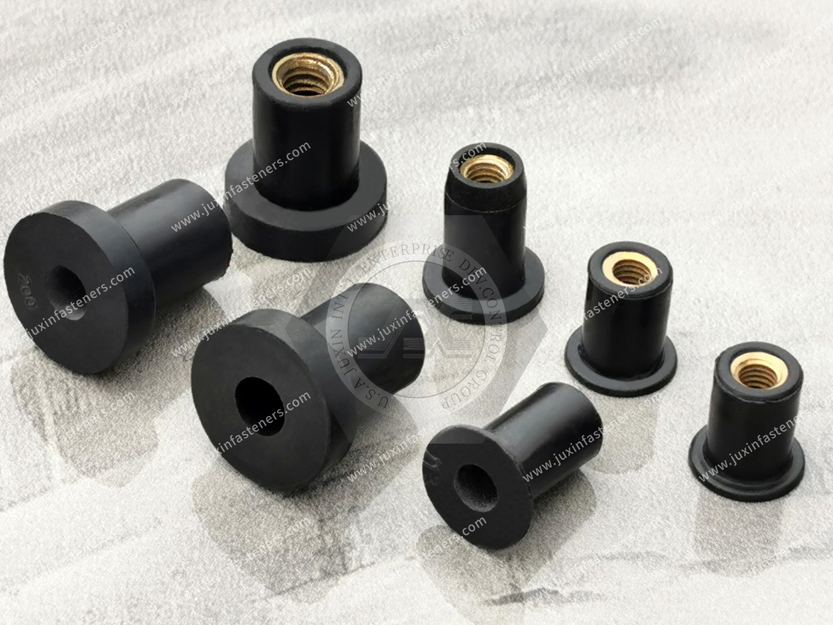
A blind rivet nut is a threaded insert designed to be installed from one accessible side of a panel or structure.
The fastener normally contains:
An internal thread
A tubular body
A flange or head
A deformable section
An installation interface for the appropriate tool
During installation, the tool pulls or deforms the body so that the blind side forms against the rear surface of the parent material.
The resulting assembly provides an internal thread without requiring access to the rear side during installation.
Blind rivet nuts can solve several common manufacturing problems.
They can be considered when:
The sheet is too thin for conventional tapping.
The rear side of the panel cannot be reached.
The structure is hollow.
A reusable threaded connection is required.
Welding is undesirable.
The parent surface has already been coated.
A removable screw connection is preferred.
A threaded mounting point must be added after panel fabrication.
Their value is therefore both mechanical and manufacturing-related.
A conventional tapped hole depends on the parent material itself providing sufficient thread engagement.
This can become difficult when the material is thin.
A blind rivet nut adds a separate threaded component to the panel.
This allows the designer to establish a dedicated internal thread without relying entirely on the thickness of the parent sheet.
The two approaches should nevertheless be compared according to:
Material thickness
Required thread engagement
Load
Assembly access
Hole preparation
Production process
Service requirements
Weld nuts and blind rivet nuts both provide internal threads, but they use different installation principles.
A weld nut is attached by welding.
A blind rivet nut is mechanically deformed into the parent material.
Blind installation can therefore be useful where:
Welding access is limited.
Heat input is undesirable.
Pre-coated surfaces must be preserved.
Post-weld finishing would add process steps.
The assembly is already partially enclosed.
The appropriate solution depends on the actual production process and joint requirements.
Through-bolting normally requires access to both sides of the assembly.
That can be impractical for:
Closed enclosures
Tubular structures
Hollow profiles
Installed panels
Confined equipment
A blind rivet nut provides the internal thread from one accessible side.
This changes the assembly architecture and can simplify component installation.
The defining feature of a blind rivet nut is that installation can be performed from one accessible side.
The installer prepares a hole, positions the insert and uses an appropriate installation tool.
The tool then deforms the body into the intended blind-side configuration.
The exact installation mechanism depends on the product design and tooling.
Therefore, installation instructions should always be based on the specific blind rivet nut rather than a generic assumption.
A simplified installation sequence is:
Prepare the specified mounting hole.
Position the blind rivet nut.
Engage the appropriate installation tool.
Apply the specified installation action.
Form the blind-side section.
Release the tool.
Inspect the installed fastener.
Install the mating screw.
The actual process parameters are product-specific.
Many blind rivet nut installation systems use a threaded mandrel or comparable pulling interface.
The tool engages the insert and generates the force needed to deform the body.
The relationship between:
Mandrel engagement
Tool movement
Fastener geometry
Grip condition
Parent material
determines how the insert forms.
This is why tool setup cannot be determined from thread size alone.
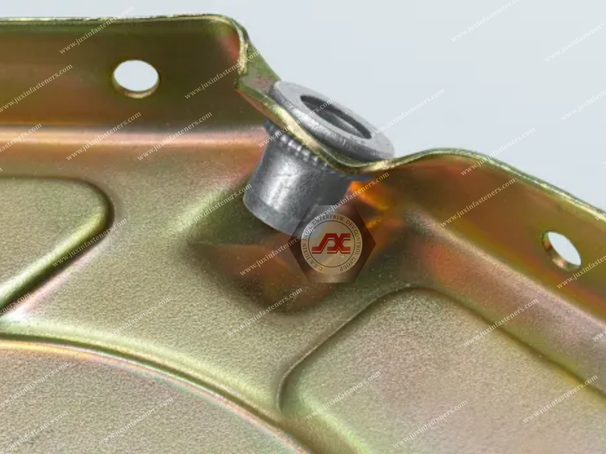
The blind-side portion of the insert is intentionally designed to deform during installation.
The resulting shape creates a mechanical bearing interface behind the panel.
The parent material is captured between the accessible-side flange and the formed blind-side section.
The exact deformation geometry varies by fastener design.
A key engineering principle is that the blind rivet nut should not be evaluated independently from the parent panel.
The installed system includes:
Blind rivet nut + mounting hole + parent material + installation process.
The same insert may behave differently when installed into:
Thin steel
Thick steel
Aluminum
Stainless steel
Plastic
Composite material
This is why application-specific validation matters.
The mounting hole is a critical part of the joint.
A hole that is too small can interfere with insertion.
A hole that is too large can reduce the intended interface between the fastener and parent material.
The correct hole size should therefore come from the product specification or approved drawing.
Nominal hole diameter is not the whole story.
The production process can create variation in:
Hole diameter
Roundness
Burr height
Edge condition
Local deformation
Hole position
These variables can influence installation consistency and joint behavior.
Burrs can interfere with seating and installation.
Depending on the application, excessive burrs may affect:
Flange seating
Hole diameter
Fastener alignment
Parent-material deformation
Installed height
Hole preparation should therefore be included in the manufacturing process specification.
Grip range describes the material condition that the fastener is designed to accommodate during installation.
It should not be treated simply as a marketing number.
The selected grip must correspond to the actual parent material and stack-up.
For a single panel, grip may closely correspond to sheet thickness.
For a multi-layer assembly, however, the effective grip condition can involve the combined thickness of the materials participating in the joint.
Examples include:
Two stacked sheets
A sheet and bracket
A panel with reinforcement
A coated assembly
Multiple layers of different materials
Therefore, procurement should provide the actual assembly condition rather than only a nominal panel thickness when requesting a quotation.
If the fastener is not appropriate for the actual grip condition, the intended blind-side deformation may not occur correctly.
Possible consequences include:
Insufficient retention
Excessive deformation
Panel damage
Incorrect installed height
Variable joint performance
Grip selection should therefore be treated as a functional parameter.
The internal thread must match the mating screw.
Common requirements may include:
Metric thread
UNC thread
Other customer-specified thread systems
Thread size, pitch and tolerance should be identified on the engineering drawing.
A nominal diameter alone does not completely define a thread.
The blind rivet nut should be selected together with the mating screw.
The designer should check:
Thread size
Thread pitch
Thread tolerance
Screw length
Required engagement
Washer use
Assembly torque
Joint stack-up
A blind rivet nut cannot be evaluated properly without considering the mating hardware.
The available internal thread must provide sufficient engagement for the intended assembly.
The required engagement depends on:
Thread size
Fastener material
Mating screw material
Joint load
Assembly design
Applicable engineering requirements
A longer internal thread is not automatically necessary for every application.
Open-end rivet nuts have an open passage through the body.
They are commonly considered for general sheet-metal applications where the screw can extend into or through the insert.
Potential applications include:
Electrical cabinets
Machinery panels
Automotive brackets
Appliance structures
Industrial enclosures
The screw length and clearance behind the insert should be checked during design.
Closed-end blind rivet nuts have a closed distal end.
They can be useful where the designer wants the screw to terminate within the insert rather than pass through the fastener.
Potential benefits can include:
Separation of the screw from the rear environment
Controlled thread termination
Reduced direct passage through the insert
However, a closed-end design should not automatically be described as waterproof.
Sealing performance depends on the complete fastener and assembly design.
Some blind rivet nuts are designed with sealing features to address specific environmental requirements.
These can be considered for applications involving:
Moisture exposure
Contamination
Enclosure interfaces
Battery-related structures
Outdoor equipment
The actual sealing capability must be validated at the system level.
A sealing rivet nut should not automatically be assigned an IP67 or IP68 rating simply because the insert contains a sealing feature.
For EV enclosure applications, see the JUXIN FASTENERS solution for Sealing Blind Rivet Nuts for EV Battery Enclosures.
IP ratings such as IP67 or IP68 describe the performance of the relevant enclosure or assembly under the applicable test conditions.
They are not automatically properties of an individual blind rivet nut.
Where an IP requirement exists, engineers should evaluate:
Fastener sealing interface
Screw interface
Washer or gasket
Panel interface
Enclosure geometry
Installation condition
Test method
For road-vehicle applications, relevant requirements may include ISO 20653 where applicable; IEC 60529 is also widely used for enclosure degrees of protection.
The flange provides the accessible-side bearing interface.
Important dimensions may include:
Head diameter
Head thickness
Flange shape
Counterbore or countersink requirements
Surface contact area
The appropriate geometry depends on the parent material and application.
Flat-head configurations are often used where a defined bearing surface is required.
They can be suitable for:
General sheet-metal assemblies
Electrical equipment
Automotive components
Industrial machinery
The head should be compatible with the panel geometry and required surface condition.
Countersunk configurations can be considered where the fastener head must sit closer to or within the panel surface.
This can be useful when:
Surface clearance is restricted.
A flush interface is required.
A mating component sits directly over the insert.
The parent material must be designed to accept the countersunk geometry.
Knurling can increase mechanical interaction between the insert body and parent material.
However, the effectiveness of the interface depends on:
Hole size
Parent material
Installation condition
Knurl geometry
Applied torque
Panel deformation
Knurling should therefore not be treated as an unconditional guarantee against rotation.
Hex or semi-hex body configurations can provide additional geometric resistance to rotation when the hole and parent material are suitable.
These designs can be useful where rotational resistance is an important requirement.
However, the complete interface remains critical.
The hole must be compatible with the body geometry.
A blind rivet nut does not resist rotation because of one feature alone.
The installed interface may depend on:
Body geometry + hole geometry + parent material + installation condition + applied torque.
This is an important distinction when comparing:
Round bodies
Knurled bodies
Hex bodies
Semi-hex bodies
The correct configuration should be selected from the actual application.
Pull-out describes axial displacement of the insert from the parent material under an applied load.
The result can depend on:
Panel material
Panel thickness
Hole diameter
Fastener geometry
Installation condition
Load direction
Pull-out should therefore be validated in the actual substrate.
Pull-through involves the fastener and/or parent material moving through the panel under load.
This can become particularly relevant in thin sheet metal.
The governing factor may be the panel rather than the fastener material.
Torque-out relates to rotational loading applied to the installed insert.
It should not be confused with pull-out.
A fastener may have adequate axial retention but insufficient resistance to rotation under a particular assembly torque.
Spin-out occurs when the insert rotates within the parent material during screw installation or removal.
Potential contributing factors include:
Hole size
Body geometry
Parent material
Installation condition
Applied torque
Panel deformation
This is one reason why anti-rotation geometry must be matched to the actual panel.
These are different engineering questions.
Pull-out asks:
How does the insert resist axial displacement?
Torque-out asks:
How does the insert resist rotation?
A specification that addresses one does not automatically address the other.
A blind rivet nut assembly may also experience lateral forces.
The joint response depends on:
Insert diameter
Panel thickness
Material strength
Screw geometry
Bracket design
Load direction
The application should be validated under the loads that actually occur in service.
If a bracket or component is mounted away from the panel surface, the insert and screw can experience a bending moment.
Longer screw projection, larger offsets and external loads can increase this effect.
The complete bracket geometry should therefore be included in engineering analysis.
Thin sheet metal is a major application for blind rivet nuts.
They can be considered when the parent material does not provide enough thickness for a conventional tapped thread.
Typical applications include:
Control cabinets
Electrical enclosures
Machinery panels
Automotive brackets
HVAC housings
Appliance panels

Automotive applications can include:
Body components
Brackets
Interior structures
Underbody components
Equipment mounting
Battery-related assemblies
The selected insert should be matched to the actual panel material, thickness, vibration condition, corrosion environment and assembly process.
EV battery systems can involve aluminum and steel structures, enclosed assemblies and demanding environmental conditions.
Blind rivet nuts can be considered for:
Battery enclosure components
Brackets
Covers
Mounting points
Thermal-management components
Auxiliary equipment
Where sealing is required, the fastener should be evaluated together with the complete enclosure.
For aluminum closed-end applications, see Aluminum Closed-End Blind Rivet Nuts: Lightweight, Sealed & Anti-Rotation Threaded Fastening Solutions.
Electrical equipment frequently uses thin sheet-metal cabinets and panels.
Blind rivet nuts can establish mounting points for:
Brackets
Covers
Cable-management components
Internal supports
Equipment modules
Where electromagnetic, environmental or grounding requirements exist, these should be treated as separate system-level requirements rather than assumed from the insert itself.
HVAC equipment commonly combines formed sheet metal with brackets and enclosed panels.
Blind rivet nuts can provide mounting points for:
Equipment supports
Covers
Brackets
Internal components
Service-related hardware
Material and finish should be selected according to the environmental conditions.
Industrial equipment can use blind rivet nuts for:
Guards
Covers
Mounting brackets
Machine panels
Equipment structures
Enclosures
They can be useful where the rear side of the structure is inaccessible during assembly.
Appliance assemblies often contain thin formed panels and enclosed structures.
Blind rivet nuts can provide reusable threaded attachment points without requiring rear-side nut access.
The selection should consider:
Panel thickness
Appearance
Load
Installation sequence
Service requirements
Blind rivet nuts can be useful in hollow structures where through-bolting is difficult.
Potential applications include:
Tubular frames
Hollow profiles
Equipment structures
Vehicle components
Machinery frames
The designer should confirm that there is sufficient clearance for the installation tool and the blind-side deformation.
Blind threaded inserts can also be considered for selected non-metallic structures.
However, plastic, fiberglass and composite materials behave differently from metals.
Relevant factors include:
Creep
Stress relaxation
Local crushing
Hole deformation
Pull-through
Temperature
Moisture
The correct insert architecture should therefore be selected for the specific substrate.
Carbon steel is widely considered for industrial applications where mechanical performance and cost are important.
Potential applications include:
Automotive structures
Machinery
Electrical enclosures
General sheet metal
Industrial equipment
Surface treatment should be specified according to the service environment and customer requirements.
Stainless steel can be selected when corrosion resistance or material compatibility is important.
Potential applications include:
Outdoor equipment
Marine-related equipment
HVAC systems
Industrial equipment
Moisture-exposed assemblies
Where applicable, ISO 3506 may be relevant to stainless steel fastener classifications within its scope. The exact product specification should determine whether and how the standard applies.
Aluminum blind rivet nuts can be considered where weight reduction is important.
However, lower density does not automatically mean equivalent mechanical performance to steel.
Engineers should consider:
Load
Thread durability
Parent material
Galvanic compatibility
Corrosion environment
Installation behavior
For a focused aluminum solution, see the JUXIN FASTENERS guide to Aluminum Closed-End Blind Rivet Nuts.
The fastener material should be evaluated together with the parent material.
Important combinations include:
Carbon steel + carbon steel
Stainless steel + stainless steel
Steel + aluminum
Stainless steel + aluminum
Metal insert + polymer substrate
The objective is not simply to choose the strongest material.
The engineer must balance:
Strength + corrosion + compatibility + weight + installation + cost.
Dissimilar metals can create galvanic-corrosion considerations when an electrolyte is present.
This can be important for:
Steel-to-aluminum assemblies
Stainless-to-aluminum assemblies
Outdoor equipment
Moisture-exposed structures
Surface treatment, environmental exposure and electrical contact should be considered together.
Surface treatment can influence corrosion behavior and appearance.
Potential systems may include:
Zinc-based coatings
Zinc-nickel coatings
Passivation for applicable stainless products
Other customer-specified finishes
The finish should be selected according to the fastener material, parent material and service environment.
Corrosion test methods should be selected according to the customer specification and application.
ASTM B117 is an example of a laboratory salt-spray test method.
However, salt-spray exposure time should not be interpreted as a direct conversion to real-world service life.
Application-specific corrosion validation remains important.
Installation can mechanically affect the fastener surface and the surrounding panel.
Potential considerations include:
Coating damage
Local surface deformation
Flange seating
Tool contact
Post-installation corrosion protection
The installation process should therefore be compatible with the specified surface-treatment system.
Stroke is the amount of tool movement used during a particular installation process.
The correct stroke depends on the fastener design and application.
It should not be inferred simply from:
Thread size
Panel thickness
Insert length
Incorrect installation settings can produce inconsistent deformation or panel damage.
Installation force is similarly product-specific.
The correct process depends on:
Fastener geometry
Material
Grip
Parent material
Tool
Installation method
Generic force values should not be transferred between different fastener designs without validation.
Blind rivet nut tools may include:
Manual tools
Pneumatic tools
Battery-powered tools
Other production installation systems
The correct tool should be compatible with the insert architecture and required production process.
Tool compatibility should be confirmed with the fastener supplier.
Excessive installation can deform the fastener or parent panel beyond the intended condition.
Possible consequences include:
Panel distortion
Damaged threads
Excessive deformation
Inconsistent installed height
Surface damage
Controlled installation is therefore part of joint quality.
Insufficient installation can prevent the blind-side section from forming correctly.
Potential consequences include:
Reduced retention
Rotation
Movement
Incorrect installed geometry
Visual inspection alone may not always be sufficient for demanding applications.
The parent panel can deform during installation.
This can be particularly relevant when working with:
Very thin sheet
Soft aluminum
Plastic
Composite panels
The installation condition should be validated against the actual substrate.
Vibration can influence the behavior of the complete threaded assembly.
Engineers should consider:
Screw loosening
Insert rotation
Panel deformation
Bracket movement
Fatigue
Where self-locking hardware is required, the insert and mating nut/screw should be considered together.
For related locking solutions, see Nylon Insert Locknuts and Self-Locking Fasteners.
Thermal cycling can change the relationship between the fastener, parent material and mating hardware.
Different materials may expand and contract at different rates.
This can affect:
Joint preload
Interface movement
Hole condition
Long-term retention
Demanding applications should include relevant thermal validation.
Environmental exposure can affect:
Corrosion
Surface treatment
Parent material
Sealing interfaces
Thread condition
The fastener specification should therefore include the actual service environment rather than simply stating “corrosion resistant.”
When blind threaded inserts are used in polymer structures, long-term behavior can differ from metal-to-metal joints.
Plastic materials can exhibit creep and stress relaxation under sustained load.
Therefore, the initial installation result may not represent long-term joint behavior.
Application-specific validation is particularly important for loaded polymer assemblies.
Grip range is more than a catalog dimension.
It connects the fastener geometry to the actual structure.
A correct selection requires knowing:
What material is being clamped?
How thick is it?
Are multiple layers involved?
Is there a coating or reinforcement?
This is why a good RFQ includes the complete stack-up.
Engineers sometimes specify the insert carefully but treat the hole as an afterthought.
That can create installation and retention problems.
The hole controls the interface between the fastener and parent material.
Therefore:
Fastener specification without hole specification is incomplete engineering.
In a thin panel, the parent material may fail before the insert material reaches its own mechanical limit.
The governing failure may be:
Pull-through
Local yielding
Hole enlargement
Panel cracking
Rotation
Therefore, a fastener's material strength should not be treated as the same thing as joint strength.
A joint can have good axial retention but poor rotational resistance.
Conversely, a geometry may resist rotation well while the parent panel remains vulnerable to axial pull-through.
This is why application validation should define the relevant failure mode before selecting the test method.
The mating screw and blind rivet nut form a joint.
Increasing screw strength does not automatically increase the capacity of:
The insert
The panel
The hole
The blind-side deformation
The complete assembly must be evaluated.
Closed-end construction can prevent a screw from passing completely through the insert.
That is different from sealing the entire assembly.
If water or dust ingress is a design concern, the engineer must evaluate the complete enclosure interface and applicable protection requirements.
Knurling, ribs, hex bodies and semi-hex bodies can all influence rotation resistance.
But the final behavior depends on the interaction between:
Fastener geometry + hole + parent material + installation process + applied torque.
This is more useful than simply labeling one geometry “high torque.”
PA, POM, PP, PC, PVDF, PEEK and other polymers can behave differently under:
Load
Temperature
Moisture
Chemicals
Long-term stress
A threaded insert selected for one polymer should not automatically be transferred to another polymer without validation.
The strongest available material may not be the best material for the complete assembly.
An insert must be considered together with:
Parent material
Coating
Environment
Moisture
Electrical contact
Temperature
This is particularly important in aluminum structures.
A technically correct fastener can still produce an inconsistent joint if:
The hole is incorrect.
The grip is wrong.
The tool is unsuitable.
Installation parameters are incorrect.
The panel is damaged during installation.
Therefore, production validation must include the installation process.
A practical selection process is:
What component will be attached?
Steel, stainless steel, aluminum, plastic, composite or another substrate?
What is the actual material thickness?
Is there one layer or multiple layers?
What hole diameter and tolerance are available?
Metric, UNC or another specified thread system?
Which grip range is required?
Round, knurled, hex, semi-hex or another configuration?
Flat, countersunk or another configuration?
Does the application require an open or closed distal end?
Carbon steel, stainless steel, aluminum or another specified material?
What corrosion and appearance requirements apply?
Which tool and installation process will be used?
Pull-out, pull-through, torque, shear, bending or combined loading?
Moisture, corrosion, vibration, temperature, chemicals or other exposure?
Which application-specific tests are required?
What drawing, quality, packaging, documentation and volume requirements apply?
A complete drawing should ideally identify:
Part number
Product type
Thread designation
Thread size and pitch
Thread tolerance where applicable
Overall dimensions
Head dimensions
Body geometry
Grip range
Material
Surface treatment
Critical tolerances
Applicable standards
Inspection requirements
Application information can be added where necessary.
Procurement teams should avoid requesting only:
“M6 blind rivet nuts.”
A more useful RFQ description is:
“M6 blind rivet nut, specified head/body geometry, defined grip range, specified parent material and thickness, required surface treatment, application environment and annual quantity.”
This produces more comparable supplier quotations.
Supplier-development teams can evaluate:
Drawing interpretation
Material control
Dimensional control
Thread control
Surface-treatment control
Installation validation
Inspection capability
Lot identification
Packaging
Change-control procedures
Production capacity
The exact requirements should follow the OEM's quality system and purchasing agreement.
Depending on customer requirements, procurement documentation may include:
Material identification
Dimensional inspection records
Surface-treatment information
Lot identification
Certificate or declaration documents where applicable
Documentation requirements should be agreed during sourcing rather than assumed for every order.
Important characteristics may include:
Thread dimensions
Head dimensions
Body dimensions
Overall length
Material
Surface treatment
Critical tolerances
The inspection plan should be based on the approved drawing.
Internal threads can be evaluated using appropriate gauges and dimensional methods.
Depending on the specification, inspection may involve:
Go/no-go gauges
Dimensional measurement
Functional mating checks
Other customer-specified inspection methods
The inspection method should match the applicable thread specification.
Dimensional consistency is particularly important for automated or repetitive assembly.
Critical dimensions may include:
Hole-related body diameter
Head diameter
Head thickness
Thread dimensions
Overall length
Grip-related dimensions
The customer and supplier should identify critical-to-function characteristics.
The most meaningful installation validation uses the actual production materials.
This should include:
Actual panel material
Actual panel thickness
Actual hole
Actual fastener
Actual installation tool
Actual mating hardware
This helps prevent the common problem of approving a fastener in a laboratory condition that does not match production.
Depending on the application, validation may include:
Pull-out testing
Pull-through testing
Torque testing
Rotation testing
Shear testing
Vibration testing
Thermal cycling
Corrosion exposure
Environmental testing
The appropriate test plan should be defined from the actual service conditions.
Production consistency depends on controlling the characteristics that affect the final joint.
These may include:
Raw material
Forming
Thread production
Heat treatment where applicable
Surface treatment
Dimensional inspection
Packaging
The exact process-control plan should reflect the customer's specification.
After approval, changes to critical product characteristics should be controlled.
Potentially significant changes include:
Material
Thread
Body geometry
Head geometry
Grip range
Surface treatment
Manufacturing process
OEM customers may have formal change-notification requirements.
Blind rivet nuts should be packaged to prevent:
Part mixing
Thread damage
Surface damage
Contamination
Quantity errors
Production packaging should also support lot and part identification where required.
The same basic fastening architecture can serve multiple industrial sectors, but the engineering requirements differ.
Body panels, brackets, structural components and equipment mounting.
Battery enclosure components, brackets, covers and auxiliary systems.
Control cabinets, electrical enclosures and equipment mounting.
Sheet-metal housings, brackets and service components.
Guards, covers, panels, frames and mounting structures.
Thin formed panels and internal equipment mounting.
Lightweight panels, equipment structures and serviceable mounting points.
The correct fastener should always be selected from the application rather than the industry name alone.
JUXIN FASTENERS supports OEM and industrial requirements involving blind rivet nuts and related threaded fastening components.
Product discussions can cover, depending on the confirmed application and product specification:
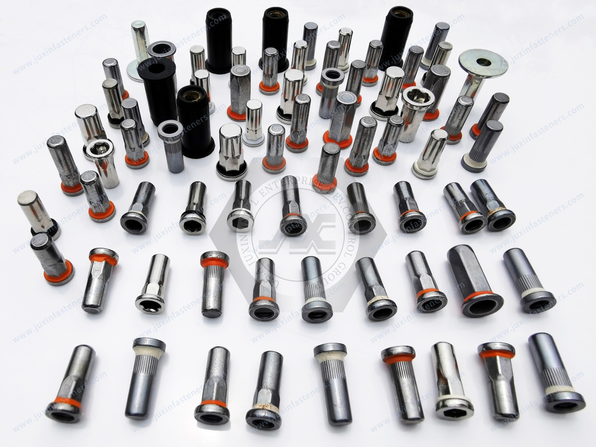
Open-end blind rivet nuts
Closed-end blind rivet nuts
Sealing blind rivet nuts
Knurled-body rivet nuts
Hex-body rivet nuts
Semi-hex rivet nuts
Aluminum rivet nuts
Stainless steel rivet nuts
Carbon steel rivet nuts
Custom blind rivet nuts
Application-specific head and body configurations
The exact material, geometry, finish, dimensional tolerance and installation requirements should be confirmed from the customer's drawing or specification.
For automotive applications involving large-cap and anti-rotation designs, see Automotive Blind Rivet Nuts: Large-Cap Design & Anti-Rotation Engineering Solutions.
For EV applications requiring a broader reliability-oriented engineering approach, see EV Blind Rivet Nuts: High-Reliability Fastening Solutions for Electric Vehicle Manufacturing.
For specialized soft-material applications, see the JUXIN FASTENERS solution for Jack Blind Rivet Nuts: Four-Leg Petal Expansion & Soft-Material Fastening Solutions.
When the parent structure is polymer-based rather than sheet metal, the insert architecture may need to be reconsidered.
Plastic fastening requires attention to:
Material creep
Stress relaxation
Temperature
Moisture
Chemical exposure
Hole deformation
Long-term loading
See the Automotive Plastic Fasteners Guide for related material and application considerations.
The engineer should start with the joint rather than the catalog.
Ask:
What is the parent material?
What is the thickness?
What is the stack-up?
What hole is available?
What thread is required?
What grip range is required?
Is anti-rotation important?
Is an open or closed end required?
Is sealing required?
What load is applied?
What environment is involved?
How will the insert be installed?
What validation is required?
This produces a more robust selection than choosing a product from thread size alone.
A procurement RFQ should translate the engineering requirement into measurable product information.
Recommended RFQ information includes:
2D drawing
3D model if available
Thread size and pitch
Head geometry
Body geometry
Grip range
Parent-material type
Parent-material thickness
Hole diameter
Material
Surface treatment
Environmental conditions
Mating screw
Annual volume
Prototype requirements
Quality documentation
Packaging requirements
When several suppliers receive only a generic description, each supplier may quote a slightly different product.
That makes price comparison difficult.
A controlled drawing establishes the common technical baseline.
Procurement can then compare:
Product conformity + quality + commercial terms + supply capability
rather than simply comparing unit prices between different products.
The prototype should represent the production joint as closely as practical.
Important variables include:
Production panel
Production hole
Production fastener
Production tool
Production mating screw
Production installation process
Changing these variables after validation may change the joint behavior.
A blind rivet nut does not have one universal performance value independent of the installation environment.
The same insert can behave differently depending on:
Material
Thickness
Hole
Grip
Installation
Loading direction
This is why supplier datasheets should be interpreted in the context of the actual application.
A strong insert can still fail to meet the application requirement if the parent panel is too weak or too thin.
The failure may occur through:
Panel pull-through
Local deformation
Hole enlargement
Rotation
Cracking
Therefore, joint validation should include the actual parent structure.
The product specification alone does not guarantee consistent production joints.
Installation is another manufacturing variable.
Control of:
Hole preparation
Grip
Tool
Installation setting
Fastener orientation
Inspection
can be essential to production consistency.
Open-end and closed-end configurations should not be treated as simple cosmetic variations.
They affect:
Screw passage
Rear-side exposure
Thread termination
Environmental interface
Assembly architecture
The correct configuration should follow the actual application requirement.
A sealing feature on a blind rivet nut can contribute to an environmental sealing strategy.
But the final result also depends on:
Panel interface
Screw
Washer
Gasket
Fastener installation
Enclosure geometry
Test conditions
Therefore, sealing claims should be made against the validated assembly rather than the fastener alone.
Many sourcing problems begin before the RFQ is released.
If the RFQ does not define:
Thread
Grip
Hole
Material
Finish
Geometry
Environment
suppliers may quote different interpretations of the same product description.
A precise engineering definition therefore improves commercial purchasing accuracy.
Blind rivet nuts provide reusable internal threads through single-sided mechanical installation.
Their main applications include:
Thin sheet metal
Hollow structures
Electrical enclosures
Automotive components
EV assemblies
HVAC equipment
Industrial machinery
Appliance panels
Selected polymer and composite structures
Reliable selection depends on more than nominal thread size.
The engineer should evaluate:
Parent material → thickness → stack-up → hole → grip → geometry → thread → installation → load → environment → validation.
The procurement team should then convert those requirements into a controlled drawing and RFQ.
If you are sourcing blind rivet nuts for an OEM or industrial application, JUXIN FASTENERS can review your requirement based on the available engineering and procurement information.
Please provide, where available:
2D drawing
3D model
Thread specification
Parent-material type
Panel thickness
Stack-up
Hole diameter
Required grip range
Head/body geometry
Material
Surface treatment
Environmental requirements
Mating screw information
Annual production volume
Validation requirements
Quality and packaging requirements
For engineering evaluation, supplier development and OEM sourcing:
Email: info@juxinfasteners.com
JUXIN FASTENERS can review the application and discuss the appropriate blind rivet nut configuration, material, dimensions, surface treatment, installation requirements and production specification.
 MORE NEWS

Sep. 25, 2026

Sep. 25, 2026

Sep. 25, 2026
Contact Us
Tel.:
+86 020 8621 0320
+86 020 3121 6067
E-mail:
Technical Support:
Navigation
SEND INQUIREY