
Call Us
+86 136 6007 9809
Call Us
+86 136 6007 9809

Aug. 23, 2023
Modern automotive manufacturing, electrical enclosure fabrication, industrial automation, appliance production,
electronics equipment and sheet-metal assembly often require a reliable external thread on a panel or structure where access to the rear side is restricted.
This creates a different fastening problem from installing an internal threaded insert.
A design engineer may need a fixed male thread extending from a sheet-metal panel so that a bracket, cover, grounding component,
cable-management part or other component can be secured with a nut. When the rear side of the panel cannot be reached during assembly,
a conventional welded stud or through-bolt may create additional manufacturing constraints.
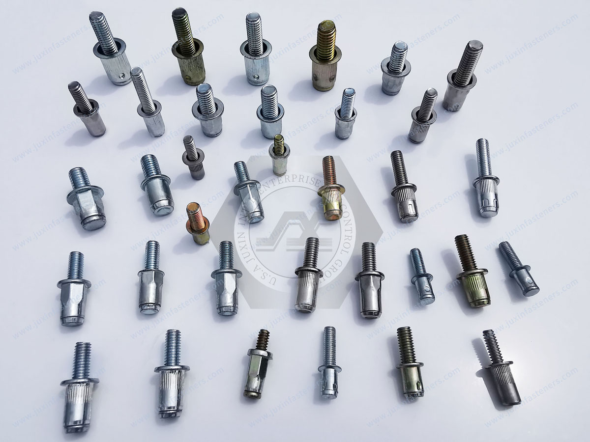
Blind threaded studs, also called blind rivet studs or pull-up studs in some industrial applications, provide a single-sided mechanical installation approach.
The stud is inserted through a prepared hole and mechanically deformed so that the blind-side portion engages the parent material.
The result is an external threaded mounting point without requiring access to the rear surface during installation.
The engineering objective is not simply to select a stud with the correct thread size. The complete fastening system includes:
The parent sheet or hollow structure
Hole diameter and hole quality
Material thickness and stack-up
Stud body geometry
Flange geometry
Blind-side deformation
Grip range
Installation stroke
Installation force
Anti-rotation characteristics
External thread dimensions
Mating nut or threaded component
Assembly torque
Environmental conditions
Required validation
For OEM and industrial procurement teams, these factors should be converted into a controlled drawing and RFQ specification rather than treated as generic catalog characteristics.
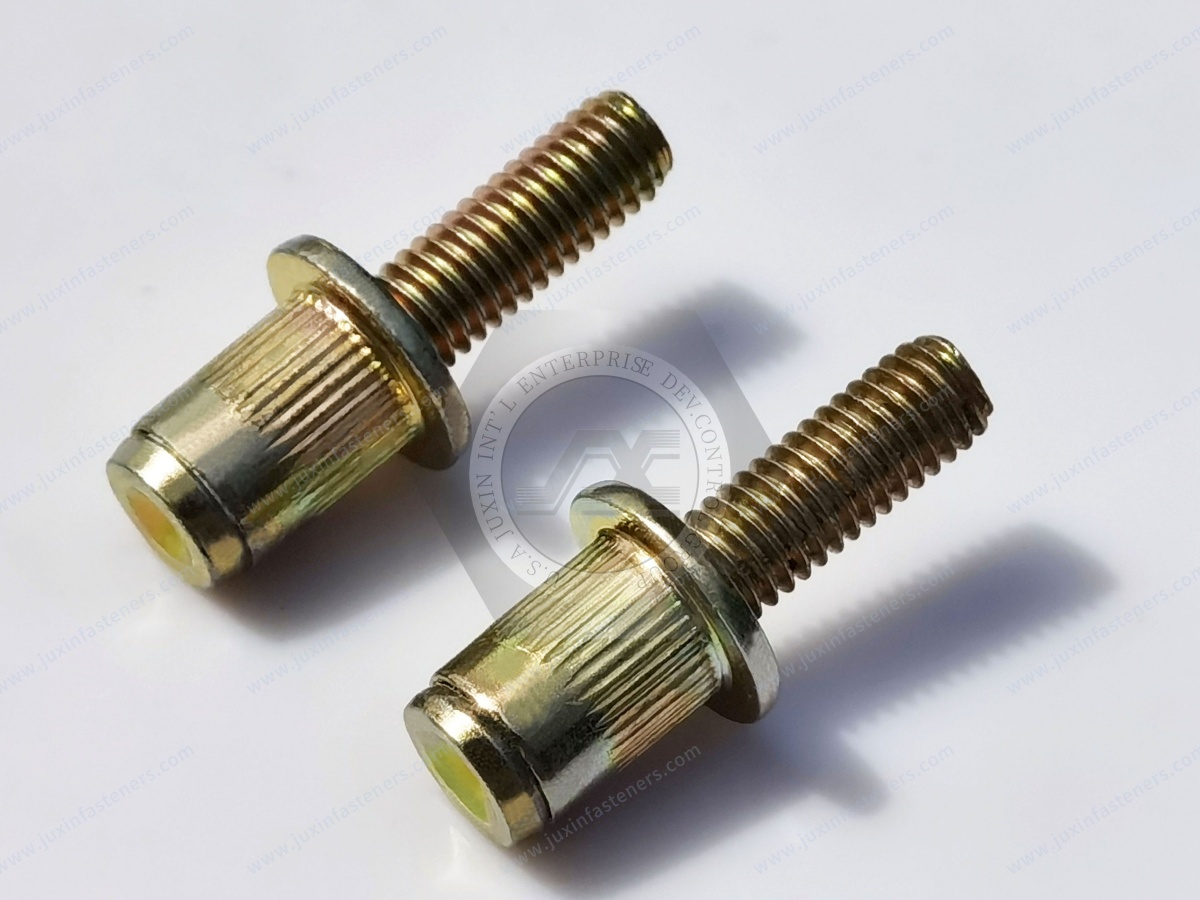
A blind threaded stud is a mechanically installed fastening component that creates an external male thread in a panel or other parent structure using installation access from one side.
Unlike a conventional bolt passing through a panel, the blind stud does not require the assembler to hold a nut or other component on the inaccessible rear side during installation.
Unlike a rivet nut, which creates an internal female thread, a blind threaded stud creates an external male thread.
This distinction is important when selecting the fastening architecture.
A typical blind threaded stud may include:
An externally threaded stud section
A flange or head
A tubular or deformable body
A blind-side deformation area
Optional knurled or other anti-rotation geometry
A defined grip range
A specified installation interface
The exact architecture varies according to the product design and application.
For this reason, engineers should evaluate the actual drawing and installation system rather than assuming that every product marketed as a “blind stud” has the same geometry or performance characteristics.
The most important distinction is the type of thread produced.
A blind rivet nut provides an internal thread.
A blind threaded stud provides an external thread.
This changes the way the mating component is mounted.
A rivet nut may be selected when a screw must be inserted into the panel from the accessible side.
A blind threaded stud may be selected when a component with a clearance hole needs to be placed over the projecting stud and secured with a nut.
The selection therefore begins with the assembly architecture.
Panel → internal threaded insert → mating screw
Panel → projecting external stud → bracket or component → mating nut
This simple difference has significant implications for component packaging, service access and assembly sequence.
For internal-thread fastening applications, see the JUXIN FASTENERS guide to Blind Rivet Nuts: Engineering Principles, Installation Mechanics & Industrial Solutions.
Weld studs remain an established fastening method for many metal assemblies.
However, welding introduces a thermal process at the installation point.
Depending on the welding method and parent material, welding can affect:
Surface coatings
Paint
Plating
Local appearance
Thermal distortion
Manufacturing sequence
Heat-sensitive surrounding components
Corrosion protection
A blind threaded stud uses mechanical deformation rather than fusion welding at the installation point.
This can make cold-mechanical installation attractive when the assembly process needs to avoid introducing welding heat into the panel.
The correct selection still depends on the application. A blind stud should not automatically be treated as a universal replacement for a welded stud.
The engineer should compare:
Required joint load
Panel material
Panel thickness
Hole design
Installation access
Production tooling
Surface finish
Environmental exposure
Assembly torque
Service requirements
Validation requirements
The defining feature of a blind threaded stud is its ability to be installed from one accessible side of the parent material.
This is particularly useful when the rear side of the panel is:
Enclosed
Difficult to access
Already assembled
Structurally inaccessible
Part of a hollow section
Hidden inside an enclosure
Located against another component
The installation process normally involves positioning the stud in the prepared hole and using an appropriate installation tool to deform the blind-side portion.
The deformation creates the mechanical engagement with the parent material.
The exact tool interface and installation sequence depend on the specific blind stud design.
Blind threaded studs rely on controlled mechanical deformation rather than thermal fusion.
During installation, the deformable portion of the stud changes geometry so that it engages the rear side of the parent panel.
The final joint therefore depends on the interaction between:
Stud geometry
Parent material
Hole geometry
Grip condition
Installation process
This is one of the most important engineering principles for the product category.
A blind stud should not be evaluated as an isolated metal component.
It is part of a mechanically formed sheet-metal joint.
Installation stroke refers to the controlled movement used by the installation system to form the blind-side portion of the stud.
The required stroke is product-specific.
It should not be replaced by a generic assumption based only on panel thickness.
Too little deformation may result in insufficient mechanical engagement.
Excessive deformation may affect the panel, stud geometry or installation consistency.
For production applications, the supplier and customer should establish the correct installation parameters for the specific stud, parent material, hole and grip condition.
Installation stroke and installation force are related but different engineering variables.
Installation stroke describes the movement used to form the joint.
Installation force describes the mechanical force required during that process.
The actual values depend on the blind stud design and installation conditions.
This distinction matters because a tool capable of producing sufficient force is not necessarily correctly configured for the required stroke.
Production engineers should therefore validate the complete installation process rather than selecting tooling based on force alone.
A common sourcing mistake is to specify the blind threaded stud without sufficiently defining the parent material.
The parent sheet influences joint behavior through:
Material strength
Hardness
Thickness
Ductility
Hole condition
Local stiffness
Surface condition
Edge distance
Proximity to bends or formed features
A stud installed into a thin aluminum panel is not mechanically equivalent to the same stud installed into a thicker steel panel.
The product selection must therefore be based on the actual assembly condition.
Grip range is one of the most important specifications when selecting a blind threaded stud.
Grip range describes the range of parent-material conditions for which the particular stud geometry and installation process are intended to form the joint correctly.
It should not be interpreted simply as “the sheet thickness.”
For example, the effective material condition may include:
One panel
Multiple stacked panels
A bracket and panel combination
Coated material
Local reinforcement
Material overlap
The RFQ should therefore identify the actual minimum and maximum stack condition.
Production assemblies rarely consist of a theoretical single sheet.
The actual joint may include several layers.
For example:
Panel + reinforcement + coating
or
Panel + bracket + coating
The total assembly condition can affect the deformation position of the blind stud.
A supplier should therefore receive the real stack-up when the application requires controlled installation behavior.
This is more useful than specifying only a nominal sheet thickness.
The mounting hole is not simply an opening through which the stud passes.
Its diameter directly affects the relationship between the stud body and parent material.
Important hole parameters include:
Nominal diameter
Diameter tolerance
Roundness
Burr condition
Edge condition
Hole location
Material deformation around the hole
An oversized hole can change the available engagement between the stud and parent material.
An undersized or damaged hole can interfere with installation.
The correct hole specification should therefore be established from the blind stud drawing and validated in the actual parent material.
Hole quality can affect installation consistency.
Drilling, punching, laser cutting and other manufacturing processes may produce different hole characteristics.
Potential variables include:
Burrs
Taper
Local distortion
Work hardening
Coating damage
Edge sharpness
Production teams should define acceptable hole conditions as part of the assembly process.
This is particularly important for high-volume OEM production where small process variations can become repeated joint variations.
Knurling is one approach used to increase resistance to rotation.
The knurled geometry interacts with the parent material around the hole during installation.
This can improve resistance to rotational movement compared with a purely smooth cylindrical interface, depending on the product design and parent material.
However, knurling should not be described as an absolute guarantee of torque resistance.
The actual result depends on:
Knurl geometry
Hole diameter
Parent material
Material thickness
Installation condition
Local panel deformation
Applied torque
Joint design
Hexagonal or partially hexagonal body designs can provide another approach to controlling rotation.
The non-circular geometry creates a mechanical interface with the parent hole.
This can be particularly useful when the mating assembly applies meaningful rotational torque to the stud.
However, a hex body does not automatically mean that the complete joint has a specified torque-out capability.
The complete assembly still requires validation.
A blind threaded stud can experience rotational movement when torque is applied to the external thread.
This is commonly described as spin-out or evaluated through torque-out resistance.
The engineering question is:
Can the installed stud remain rotationally stable under the specified assembly torque?
The answer depends on the entire stud-to-panel interface.
Therefore, “anti-rotation” should be treated as a design requirement rather than simply a product-name feature.
Pull-out evaluates a different direction of loading.
A stud may resist rotation effectively while still having insufficient resistance to axial loading.
This is why procurement specifications should not use “anti-rotation” as a substitute for overall joint strength.
Relevant failure modes can include:
Rotation
Axial pull-out
Pull-through
Local panel deformation
Stud deformation
Thread damage
Panel cracking
Each should be considered according to the actual application.
Some blind threaded stud applications subject the projecting stud to lateral loading.
Examples include:
Brackets
Cable supports
Equipment mounts
Interior automotive components
Electrical hardware
Shear behavior depends on the stud cross-section, unsupported length, parent panel, loading direction and complete joint geometry.
The designer should not assume that a stud with a large thread diameter automatically provides a high-capacity sheet-metal joint.
External thread length must match the mating component.
Important considerations include:
Bracket thickness
Washer thickness
Nut dimensions
Required thread engagement
Available clearance
Component stack-up
Service access
An unnecessarily long stud can create packaging problems.
An insufficiently long stud can prevent the mating nut from achieving the intended engagement.
Thread length should therefore be specified at drawing level.
Blind threaded studs can be specified with the external thread required by the assembly.
Common industrial requirements may include metric or inch thread systems depending on the target market and equipment.
The RFQ should identify:
Thread diameter
Thread pitch
Thread class where applicable
Thread length
End condition
Mating nut requirement
The supplier should not infer the thread specification solely from the application name.
The blind threaded stud and mating nut form one fastening interface.
The engineer should confirm:
Thread compatibility
Nut type
Washer requirements
Assembly torque
Material compatibility
Coating compatibility
Service environment
For locking requirements, a suitable prevailing-torque or other locking nut may be considered where appropriate.
JUXIN FASTENERS also supplies Nylon Insert Locknuts for Self-Locking Fastening Applications.
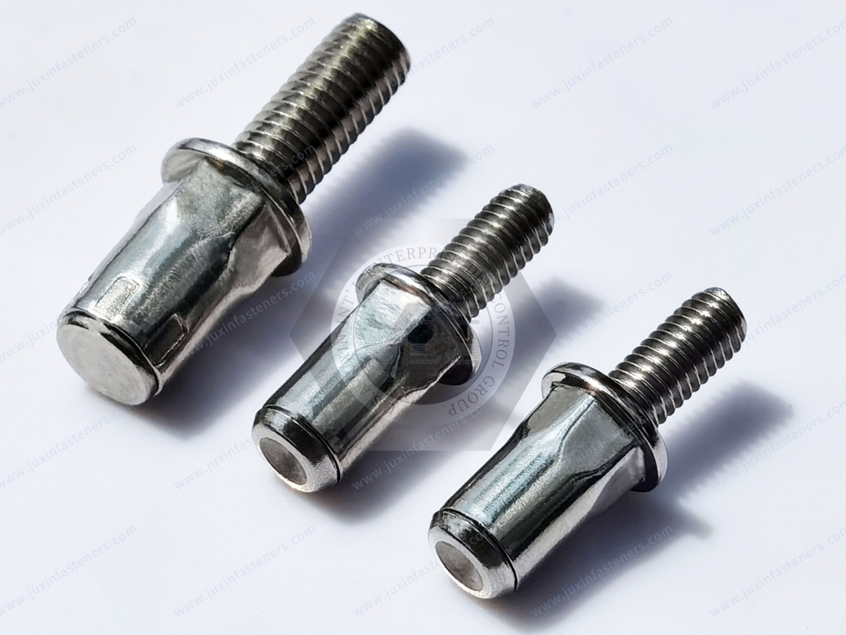
The assembly direction often determines whether an external or internal thread is preferable.
Choose an external threaded stud when:
The mounted component can pass over the stud
A nut can be installed from the accessible side
A projecting threaded point is desirable
The rear side is inaccessible
A fixed stud position simplifies assembly
Choose an internal threaded insert when:
A screw should enter the fastening point from the accessible side
The mounted component cannot pass over a projecting stud
Internal thread engagement is preferred
The fastening architecture should be decided together with the product design.
Automotive assemblies frequently contain thin sheet-metal structures, brackets and enclosed components where rear-side access is restricted.
Potential applications include:
Body brackets
Interior mounting points
Electrical equipment
Control modules
Brackets
Covers
Cable-management components
HVAC-related assemblies
Structural sheet-metal subassemblies
The appropriate product depends on the parent material, joint loading, corrosion environment and production process.
For broader automotive fastening requirements, see Industrial & Automotive Bolts and Nuts.
Electrical cabinets and equipment enclosures often require mounting points for:
Brackets
Cable-management systems
Covers
Electrical components
Support hardware
Internal mounting assemblies
Single-sided installation can simplify assembly where the inside or rear side of the enclosure is difficult to access during production.
The external thread also provides a convenient fixed mounting point for components secured with nuts.
Automation equipment may contain:
Guarding
Sheet-metal frames
Control cabinets
Sensor brackets
Cable supports
Access panels
Equipment covers
Blind threaded studs can provide repeatable external mounting points where the design requires one-sided installation.
The final selection should consider vibration, service frequency, assembly torque and the mechanical condition of the parent material.
Electronic equipment housings may use thin sheet metal combined with painted, plated or otherwise finished surfaces.
A cold-mechanical fastening method can be attractive when the manufacturing process needs to avoid introducing welding heat at the installation point.
However, the surface finish, hole preparation and installation sequence should be evaluated together.
Appliance and HVAC equipment commonly uses formed sheet-metal structures with limited access to certain surfaces.
Blind threaded studs can be considered for:
Brackets
Panels
Covers
Mounting hardware
Internal supports
The correct product depends on the sheet material, thickness, environmental exposure and assembly requirements.
Electric vehicle manufacturing increasingly uses aluminum and other lightweight sheet structures.
Blind threaded studs may be considered for selected:
Brackets
Electrical component mounting
Battery-related support components
Enclosure hardware
Cable and component attachment points
However, battery enclosure applications require particular attention to sealing, corrosion compatibility, electrical considerations and assembly validation.
A blind threaded stud should not automatically be described as a sealing or IP-rated component unless the specific design and assembly have been validated for that requirement.
For sealed blind fastening requirements, see Sealing Blind Rivet Nuts for EV Battery Enclosures.
Aluminum sheet introduces specific engineering considerations.
Compared with many steel sheet applications, aluminum can have different:
Material strength
Hardness
Ductility
Local deformation behavior
Thermal expansion
Galvanic compatibility considerations
The blind stud design and installation process should therefore be validated specifically in the intended aluminum alloy and thickness.
A product that performs appropriately in steel should not automatically be assumed to behave identically in aluminum.
Stainless steel panels may be selected for:
Corrosion-exposed equipment
Food-processing equipment
Industrial machinery
Electrical equipment
Architectural or appearance-sensitive assemblies
When stainless steel is used as the parent material, the stud material and surface finish should be considered together.
Potential issues include:
Galvanic compatibility
Appearance
Corrosion behavior
Hole deformation
Installation force
Local surface damage
The surface treatment of a blind threaded stud should be selected according to the application environment.
Potential requirements may involve:
Zinc-based finishes
Zinc-nickel systems
Stainless steel construction
Other application-specific finishes
The correct choice depends on the parent material and environmental exposure.
A coating designation alone should not be treated as a complete corrosion-service specification.
When dissimilar metals are combined, galvanic corrosion can become a system-level consideration in the presence of a suitable electrolyte.
This is particularly relevant to combinations such as:
Steel stud + aluminum panel
Stainless steel stud + aluminum panel
Coated carbon steel stud + conductive metal panel
The engineer should consider:
Material pairing
Surface treatment
Moisture exposure
Electrical contact
Joint geometry
Service environment
The fastening material should be selected as part of the complete corrosion-control strategy.
One potential advantage of cold-mechanical installation is that the fastening operation does not require welding heat at the installation point.
This can create additional manufacturing-sequence options.
Depending on the application, engineers may evaluate installation relative to:
Painting
Powder coating
Plating
Anodizing
Other finishing processes
However, it is not correct to assume that every blind stud can automatically be installed after every coating process.
The actual hole condition, coating thickness, accessibility, installation tooling and required electrical or corrosion performance must be validated.
In applications where the fastening design permits installation after finishing, the production process may be separated into:
Sheet-metal fabrication
Surface finishing
Blind stud installation
Component assembly
This can reduce the need to expose a welded fastening operation to already-finished panels.
The benefit is therefore primarily a process-sequencing opportunity, not an automatic performance guarantee.
Manufacturing engineering teams should evaluate the actual process flow before changing the installation sequence.
Finished sheet metal can be sensitive to:
Scratching
Tool contact
Local deformation
Coating damage
Contamination
Installation tooling should therefore be evaluated together with the finished panel.
Where appearance is critical, the assembly process should include appropriate controls for tool contact and panel protection.
Knurling and hex geometry work through interaction with the parent material.
Therefore, the same anti-rotation geometry may behave differently in:
Thin steel
Thick steel
Aluminum
Stainless steel
Harder sheet
Softer sheet
The correct design should match the parent material and hole condition.
This is an important Information Gain point for procurement: anti-rotation geometry cannot be specified independently from the receiving hole.
The distance between the blind stud hole and the panel edge can affect local material behavior.
If the hole is too close to an edge, installation and loading may interact with:
Edge deformation
Panel splitting
Local bending
Reduced bearing area
The appropriate minimum edge distance should therefore be determined from the specific product design, parent material and engineering validation rather than applying one universal number.
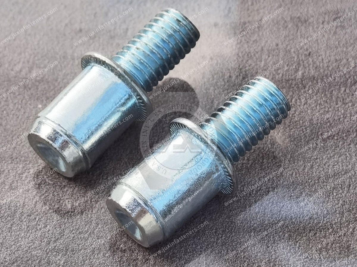
A blind stud installed near a bend may experience a different local stiffness condition from one installed in a flat panel.
Potential considerations include:
Bend radius
Distance from bend
Panel thickness
Local reinforcement
Stud orientation
Assembly loading
Designers should identify nearby formed features on the drawing when requesting a fastening solution.
Joint behavior depends not only on material thickness but also on local stiffness.
A thin sheet with nearby ribs or formed features may behave differently from an unsupported flat sheet of the same nominal thickness.
For critical assemblies, the supplier should receive enough information to understand the actual installation location.
Automotive, industrial automation and machinery applications may expose blind threaded studs to vibration.
The engineer should consider:
Joint preload
Stud rotation
Mating nut locking method
Panel deformation
Repeated loading
Service temperature
Maintenance cycles
Anti-rotation of the stud does not automatically prevent loosening of the mating nut.
These are separate mechanisms and should be evaluated separately.
Temperature changes can alter the behavior of the complete fastening system.
Potential variables include:
Thermal expansion differences
Parent panel movement
Coating behavior
Mating hardware
Joint preload
Material compatibility
For EV, automotive and outdoor industrial applications, the actual temperature range and duty cycle should be included in the validation plan when relevant.
Some applications require repeated removal and reinstallation of the mounted component.
In such cases, engineers should consider:
Mating nut type
Thread wear
Stud rotation
Surface condition
Installation torque
Service tooling
Number of expected service cycles
A blind stud should therefore be evaluated not only for initial installation but also for the intended service environment.
A blind threaded stud may be considered when the application requires:
External male thread
Single-sided installation
Limited rear access
Sheet-metal mounting
Mechanical rather than welded installation
A projecting mounting point
Controlled assembly sequence
The final selection should still be based on the actual joint requirements.
A different fastening method may be more appropriate when:
An internal thread is required
The assembly requires a flush surface
The parent structure cannot support the required mechanical deformation
Access conditions favor a conventional through-bolt
Welding is already an established and validated process
The application has unusually high structural loading
Special electrical or sealing requirements require another fastening architecture
The objective is to select the correct fastening system rather than force one product category into every application.
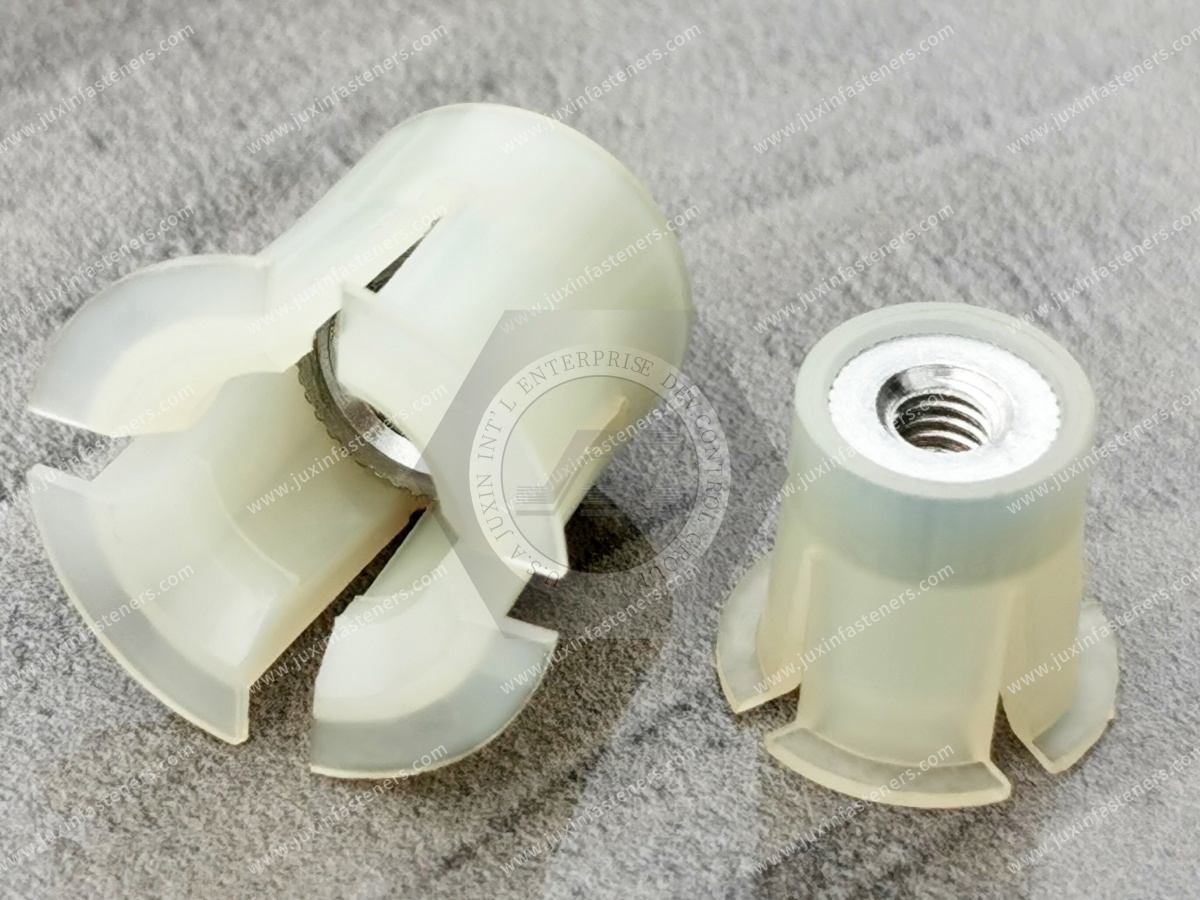
Through-bolts provide a familiar mechanical fastening arrangement but normally require access to both sides during installation.
Blind threaded studs can simplify installation where the rear side is inaccessible.
The trade-off is that the parent panel and blind deformation zone become critical elements of the joint.
The correct choice therefore depends strongly on assembly access and panel architecture.
| Requirement | Blind Threaded Stud | Welded Stud |
|---|---|---|
| Rear-side installation access | Typically not required | Depends on welding configuration |
| Installation principle | Mechanical deformation | Welding |
| Heat at installation point | No welding heat introduced | Welding heat introduced |
| External thread | Yes | Yes |
| Coated panel process | Can offer additional process options | Welding usually requires process planning before finishing |
| Hole required | Typically yes | Depends on welding design |
| Anti-rotation | Product and hole dependent | Welding joint dependent |
| Validation | Joint-specific | Joint-specific |
This comparison is a starting point only. Final selection should be based on the actual production process and joint requirements.
| Requirement | Blind Threaded Stud | Blind Rivet Nut |
|---|---|---|
| Thread type | External male thread | Internal female thread |
| Typical mating hardware | Nut | Screw |
| Mounting direction | Component passes over stud | Screw enters insert |
| Rear access | Not normally required | Not normally required |
| Typical use | Bracket or component mounted over a stud | Component secured with a screw |
| Anti-rotation | Stud-to-panel interface | Insert-to-panel interface |
The assembly architecture should determine which thread direction is required.
A blind threaded stud may be available in different body and head configurations.
Important product variables can include:
Stud diameter
Thread pitch
Thread length
Overall length
Flange diameter
Flange thickness
Body geometry
Knurling
Hex or other anti-rotation geometry
Open or closed construction where applicable
Material
Surface finish
These characteristics should be specified from the application rather than selected solely by nominal thread size.
Potential material families for blind threaded studs may include:
Carbon steel
Stainless steel
Aluminum
Other application-specific alloys where available
The material selection should consider:
Joint loading
Corrosion environment
Parent material
Weight requirements
Temperature
Electrical considerations
Surface finish
Procurement requirements
Material availability must be confirmed against the actual JUXIN FASTENERS product specification.
Stainless steel may be considered where corrosion resistance or material compatibility is important.
For stainless fastener applications, the applicable product and material requirements should be confirmed against the relevant international specification.
ISO 3506 may apply to specific stainless steel fasteners within its defined scope; it should not be presented as a universal standard for every blind threaded stud design.
The exact material grade and product standard should therefore be stated on the drawing or technical specification.
Blind threaded studs should be specified according to the actual product geometry and applicable standard.
A key procurement principle is:
Do not attach an international standard simply because it appears in a competitor catalog.
The applicable specification should match the product type, material and dimensional requirements.
Where a product is based on a recognized DIN, ISO, ASME/ANSI, EN or other international specification, the exact designation and scope should be confirmed for the requested configuration.
Material standards should similarly be applied only within their defined scope.
This prevents incorrect standard cross-references from entering an OEM drawing or purchasing specification.
A supplier statement such as “ISO compliant” does not tell an engineer which characteristic is controlled.
An OEM specification should instead identify relevant requirements such as:
Product geometry
Thread
Material
Finish
Dimensions
Tolerances
Grip range
Installation requirements
Inspection requirements
Packaging
Traceability requirements where required
This creates a more useful and auditable purchasing specification.
Quality control should focus on characteristics that can affect assembly.
Potential inspection areas include:
External thread dimensions
Stud length
Flange dimensions
Body geometry
Hole-fit dimensions
Surface finish
Material
Visual condition
Functional installation characteristics
The exact inspection plan should be based on the approved drawing and customer specification.
External thread inspection should verify the requirements defined on the drawing.
Depending on the thread specification, appropriate gauges and dimensional inspection methods may be used.
Important characteristics can include:
Major diameter
Pitch
Thread profile
Thread length
Thread condition
Functional fit with the mating nut
The supplier should maintain clear product identification and revision control for production parts.
Production validation should use the actual:
Stud
Parent material
Hole
Grip condition
Installation tool
Installation parameters
Mating hardware
Testing only the stud as a loose component cannot reproduce the actual sheet-metal joint.
This is one of the most important distinctions between component inspection and joint validation.
Engineers evaluating a blind threaded stud should consider several possible failure modes.
These may include:
Stud spin-out
Pull-out
Pull-through
Panel deformation
Stud bending
Thread damage
Local cracking
Corrosion
Mating nut loosening
The relevant failure modes depend on the application.
A supplier should not replace application-specific validation with a generic product claim.
A strong OEM RFQ should include as much of the following information as possible:
2D drawing
3D model where available
Thread specification
Thread length
Overall stud length
Flange dimensions
Body geometry
Parent material
Parent material thickness
Minimum and maximum stack-up
Hole diameter
Hole tolerance
Hole-making process
Anti-rotation requirement
Environmental conditions
Surface finish
Mating nut specification
Assembly torque
Installation tooling information
Annual or forecast volume
Packaging requirements
Inspection requirements
Traceability requirements
Sample requirements
Required validation
This information allows the supplier to evaluate the application rather than simply quote a visually similar catalog component.
Procurement teams should avoid sending an RFQ that contains only:
“Blind threaded stud, M6.”
That description is normally insufficient for controlled OEM sourcing.
A procurement specification should connect the commercial part number to:
Approved drawing
Revision
Material
Finish
Thread
Geometry
Grip
Installation requirement
Quality requirements
Packaging
Annual demand
This reduces the risk of receiving technically different products under apparently similar descriptions.
Supplier development teams may evaluate:
Drawing interpretation
Process capability
Material control
Surface-treatment control
Thread inspection
Production traceability
Change management
Sample approval
Process consistency
Nonconformance response
Packaging control
Delivery performance
These are supplier-qualification considerations rather than inherent product specifications.
They should be established according to the customer's quality system and purchasing requirements.
Before approving a blind threaded stud, the design engineer should confirm:
Is an external thread actually required?
Is rear-side access restricted?
What is the parent material?
What is the actual thickness or stack-up?
What hole diameter is required?
Is anti-rotation necessary?
What assembly torque will be applied?
What load direction is expected?
What is the required stud projection?
What mating nut will be used?
Is corrosion compatibility acceptable?
Does the finished surface require protection?
Does the assembly require sealing?
What validation is required?
This checklist helps convert the fastening concept into an engineering specification.
For purchasing and sourcing teams, the checklist should extend beyond price.
Confirm:
Approved drawing
Part number
Revision
Material
Finish
Thread
Grip range
Packaging
Inspection requirements
Sample approval status
Annual volume
Forecast
Delivery requirements
Change-control expectations
Documentation requirements
The lowest unit price is not necessarily the lowest total procurement risk.
Blind threaded studs interact directly with the customer's sheet-metal design.
A technically experienced supplier can identify potential issues such as:
Incorrect grip selection
Incompatible hole diameter
Missing anti-rotation requirement
Insufficient stud projection
Mating nut mismatch
Unclear material specification
Surface-finish incompatibility
This is why a drawing-based RFQ is generally more useful than a product-name-only inquiry.
JUXIN FASTENERS supports B2B requirements for custom and application-specific fastening components.
For blind threaded stud projects, the technical evaluation should focus on the customer's actual:
Drawing
Thread
Material
Finish
Parent panel
Thickness
Hole
Grip condition
Stud geometry
Installation method
Application environment
Volume requirement
The objective is to identify a fastening configuration appropriate to the customer's assembly rather than promote one generic stud design.
Blind threaded studs are often only one part of a larger fastening program.
Depending on the application, the same OEM project may require:
Blind rivet nuts
Sealing blind rivet nuts
Self-clinching fasteners
Weld fasteners
Custom bolts
Locking nuts
Stainless steel fasteners
CNC-machined components
Plastic fastening components
JUXIN FASTENERS can therefore evaluate the fastening requirement at the assembly level when multiple fastening technologies are involved.
For lightweight polymer applications, see Custom Plastic & Nylon Fasteners for Industrial Applications.
Some assemblies combine a mechanically installed stud with high-strength or locking mating hardware.
The stud, nut and parent panel should be treated as one joint.
Using a high-strength nut does not automatically make the entire assembly a high-strength joint.
The weakest relevant interface may instead be:
Parent sheet
Blind-side deformation
Stud body
Thread
Mating nut
Bracket
Local panel structure
For related fastening requirements, see High-Strength Bolts and Nuts.
OEM applications may require dimensions that are not represented by a standard catalog configuration.
Custom requirements can include:
Thread size
Thread length
Stud projection
Flange geometry
Body geometry
Anti-rotation design
Material
Surface treatment
Grip range
Packaging
Custom does not mean that every feature should be changed independently.
The design should remain connected to the installation mechanism and parent material.
For production programs, the approved drawing should control the critical product characteristics.
This may include:
Dimensions
Tolerances
Thread specification
Material
Finish
Functional requirements
Inspection requirements
Revision level
A drawing-controlled process provides greater consistency than relying on a product photograph or informal product name.
Prototype evaluation should reproduce the intended production assembly as closely as practical.
The evaluation should consider:
Actual panel material
Actual panel thickness
Actual hole
Actual blind stud
Actual installation tooling
Actual mating hardware
This helps identify problems before production release.
Once the design is approved, production validation should confirm that the selected blind threaded stud and installation process remain suitable under the intended manufacturing conditions.
Where relevant, validation can examine:
Installation consistency
Stud seating
Rotation resistance
Axial retention
Panel condition
Thread condition
Environmental exposure
Assembly torque
Service requirements
The specific test methods and acceptance criteria should come from the customer's engineering specification.
One of the most useful principles when sourcing blind threaded studs is:
The catalog name identifies the product category; the joint specification determines whether the product is suitable.
“Blind threaded stud” alone does not define:
Parent material
Hole size
Grip
Anti-rotation
Load
Corrosion environment
Installation process
Mating hardware
Therefore, engineers and procurement teams should move from product-category searching toward application-specific specification.
Another important principle is that anti-rotation is not created by the stud alone.
The final rotational resistance depends on:
Stud geometry + hole + parent material + installation condition + applied torque
This is why knurled, hex and other anti-rotation designs must be evaluated against the actual receiving panel.
It is also why a supplier should not promise a universal torque-out value without a defined test configuration.
Grip selection should reflect the actual material condition surrounding the installed stud.
The correct question is not simply:
“What thickness is the sheet?”
It is:
“What material stack and installation condition will the stud actually clamp?”
This distinction is particularly important for assemblies containing multiple panels, brackets, coatings or local reinforcement.
The same blind threaded stud can produce different installation results when process conditions change.
Important variables include:
Tool type
Tool setting
Installation stroke
Installation force
Hole condition
Grip condition
Operator or automated process
Panel support
Therefore, tooling should be considered part of the manufacturing process rather than an afterthought.
Choosing an external stud instead of an internal insert changes the complete assembly.
An external stud may allow:
Bracket placement over the stud
Nut installation from the accessible side
Fixed component location
Simple component replacement
But it also requires:
Adequate stud projection
Suitable nut access
Clearance around the stud
Correct thread engagement
Appropriate anti-rotation behavior
The thread direction should therefore be decided during product design, not after the panel architecture is already fixed.
A practical OEM sourcing process can follow this sequence:
Application → Parent Material → Thickness / Stack-Up → Hole → Thread → Stud Geometry → Grip → Anti-Rotation → Installation → Mating Hardware → Environment → Validation → Drawing → Volume → RFQ
This creates a clear bridge between engineering requirements and procurement requirements.
For design engineers, the priority is joint suitability.
For procurement teams, the priority is controlled specification, repeatability, documentation and supply continuity.
Both requirements should meet in the same RFQ.
For the fastest technical evaluation, provide:
2D drawing
3D model if available
Part number or reference part
Thread specification
Parent panel material
Panel thickness
Stack-up
Hole diameter
Hole tolerance
Required stud projection
Anti-rotation requirement
Surface finish
Environmental conditions
Mating nut
Assembly torque
Estimated annual quantity
Prototype quantity
Required quality documentation
If some information is not yet available, send the drawing and application description first.
The engineering team can then identify which additional parameters need to be confirmed.
JUXIN FASTENERS approaches blind threaded stud sourcing from the complete fastening-system perspective.
The objective is not simply to quote a threaded stud by diameter.
The objective is to align:
Product geometry
Parent material
Hole design
Grip condition
Installation process
Thread requirement
Surface treatment
Mating hardware
Validation requirements
Production volume
This approach supports both engineering development and controlled procurement.
When selecting blind threaded studs, remember these core principles:
A blind threaded stud creates an external thread through single-sided mechanical installation.
It is different from a blind rivet nut, which creates an internal thread.
It provides an alternative fastening architecture to welded studs in applications where mechanical installation is appropriate.
The parent sheet is part of the joint.
Hole diameter and hole quality are critical.
Grip range should reflect the actual stack-up.
Installation stroke and installation force are different process variables.
Knurling and hex geometry can support anti-rotation but do not guarantee a universal torque-out result.
Pull-out, pull-through, shear and rotation are different failure modes.
The mating nut and bracket are part of the complete fastening system.
Coated-panel installation can create manufacturing-sequence advantages, but the actual process must be validated.
Material and surface finish should be selected for the complete service environment.
International standards should be applied according to their actual scope.
OEM procurement specifications should be drawing-controlled.
Application-specific validation is more meaningful than generic catalog claims.
If your application requires a blind threaded stud, blind rivet stud, pull-up stud or custom external-thread fastening solution,
JUXIN FASTENERS can evaluate the requirement based on your actual engineering and procurement specifications.
For OEM and industrial sourcing, please provide your drawing, thread requirement, parent material, panel thickness, hole information, grip condition, installation requirements and expected volume.
Email: info@juxinfasteners.com
JUXIN FASTENERS can then review the fastening architecture and determine the technical information required for quotation, sample evaluation and production sourcing.
For related internal-thread applications, explore our Blind Rivet Nuts Engineering Solutions.
For automotive applications, see our Industrial & Automotive Bolts and Nuts Solutions.
For broader sheet-metal and lightweight fastening requirements, JUXIN FASTENERS can also evaluate the appropriate combination of metal and polymer fastening components for your OEM assembly.
 MORE NEWS

Sep. 25, 2026

Sep. 25, 2026

Sep. 25, 2026
Contact Us
Tel.:
+86 020 8621 0320
+86 020 3121 6067
E-mail:
Technical Support:
Navigation
SEND INQUIREY