
Call Us
+86 136 6007 9809
Call Us
+86 136 6007 9809

Aug. 23, 2023
In modern sheet-metal fabrication, automotive assembly, electrical enclosure manufacturing, industrial automation,
appliance production and equipment manufacturing, design engineers frequently need to create a reliable external threaded mounting point on a panel or hollow structure where access to the rear side is restricted.
This requirement is different from creating an internal thread.
A blind threaded stud, also called a blind rivet stud or pull-up stud in some industrial applications, creates a projecting male thread through a cold-mechanical installation process.
The stud is positioned through a prepared hole and mechanically deformed so that its blind-side section engages the parent material.
This fastening architecture can be useful when:
The rear side of the panel cannot be accessed
A projecting external thread is required
A bracket or component must pass over the stud
A nut is used as the mating fastener
Welding heat should be avoided at the installation point
A finished or coated panel requires a different assembly sequence
The application uses thin or hollow sheet-metal structures
However, selecting a blind threaded stud is not simply a matter of choosing M4, M5, M6 or another nominal thread size.
A complete engineering specification may need to define:
Thread diameter
Thread pitch
Thread system
Thread length
Stud projection
Flange geometry
Body geometry
Anti-rotation design
Grip range
Parent material
Parent material thickness
Stack-up
Hole diameter
Hole tolerance
Hole condition
Material
Surface treatment
Mating nut
Installation method
Assembly torque
Environmental requirements
Validation requirements
For OEM procurement, these requirements should ultimately be controlled by the approved drawing and technical specification.
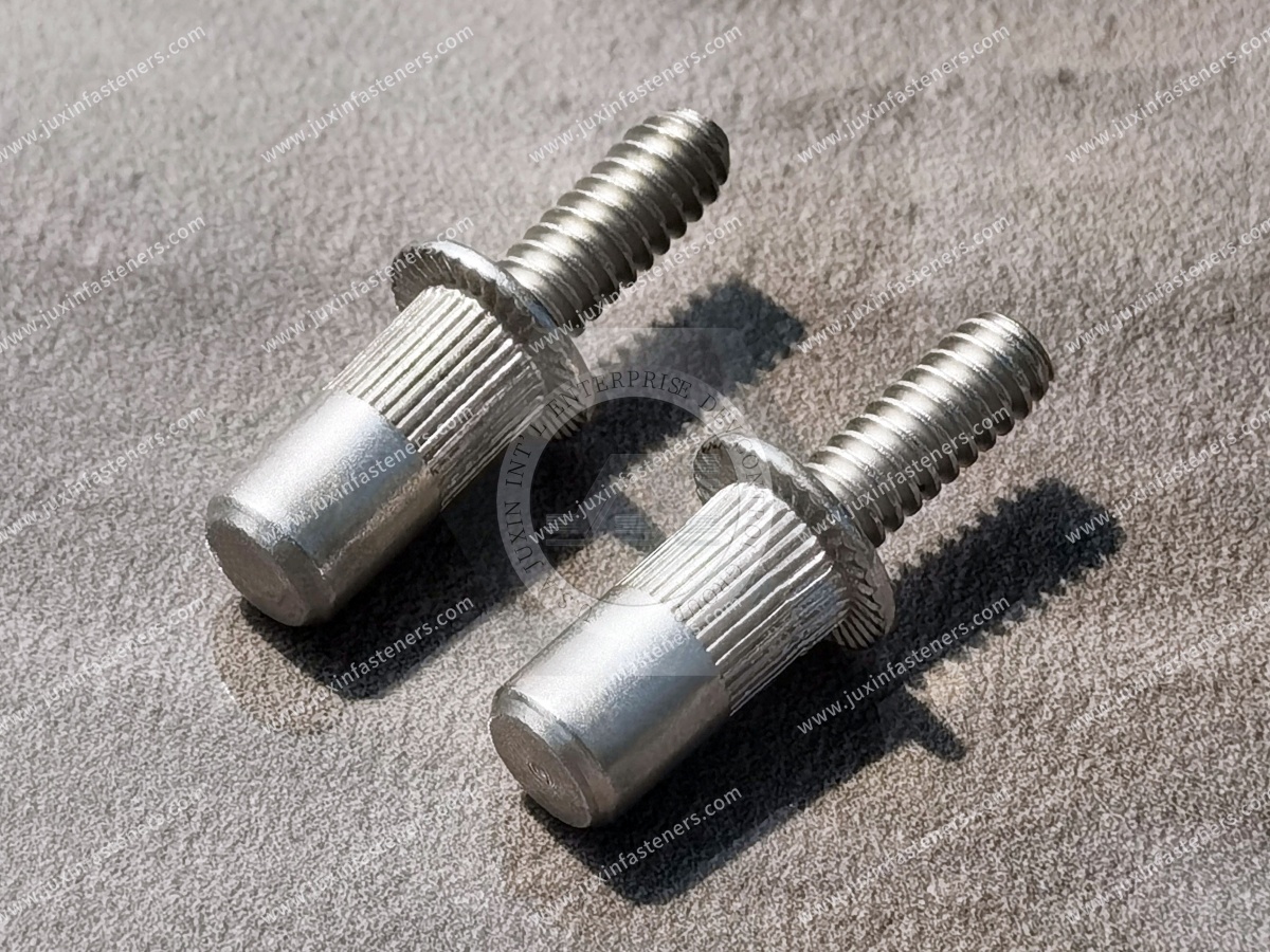
A blind threaded stud is a mechanically installed fastener that creates an external male thread in a parent panel using access from one side.
The basic assembly consists of:
Parent panel → mechanically installed stud → projecting external thread → mounted component → mating nut
The stud typically contains:
An external threaded section
A flange or head
A deformable body
A blind-side deformation area
Optional anti-rotation geometry
The exact geometry depends on the specific product design.
The installation process creates a mechanical interface between the stud and parent material.
The final joint therefore depends on the interaction between the component and the receiving structure.
The most important specification characteristic is the thread direction.
A blind threaded stud creates a male thread.
This makes it suitable for applications where the mounted component contains a clearance hole and is secured with a nut.
For comparison:
Blind threaded stud:
Panel → external thread → component → nut
Blind rivet nut:
Panel → internal thread → component → screw
The two products may look related because both can be installed from one side, but their assembly architecture is different.
For internal-thread applications, see Blind Rivet Nuts: Engineering Principles, Installation Mechanics & Industrial Solutions.
A catalog description such as:
“M6 blind threaded stud”
does not fully define the product.
Two M6 blind studs may differ in:
Stud length
Thread length
Flange diameter
Body diameter
Grip range
Anti-rotation geometry
Material
Surface treatment
Installation requirements
They may therefore behave differently in the same sheet-metal application.
This is why engineering drawings and RFQs should specify the characteristics that actually control the joint.
Thread size is usually one of the first parameters considered.
Common industrial applications may use metric threads or inch-based UNC/UNF thread systems depending on the customer's drawing and market.
Possible thread requirements can include:
M3
M4
M5
M6
M8
M10
M12
UNC
UNF
These examples should not be interpreted as a universal JUXIN FASTENERS stocked range.
The available configuration must be confirmed against the specific product design and customer requirement.
For metric blind threaded studs, the drawing should identify:
Nominal diameter
Pitch
Thread tolerance/class where applicable
Thread length
End condition
For example, “M6” identifies the nominal thread diameter but does not by itself define every dimensional requirement needed for controlled procurement.
The pitch and applicable thread tolerance should therefore be identified where required by the engineering specification.
North American OEM programs may require inch-series threads.
Two common categories are:
UNC — Unified National Coarse
UNF — Unified National Fine
The actual thread designation should come directly from the customer drawing.
The supplier should not assume that a metric equivalent is acceptable simply because the nominal diameter is similar.
Thread interchangeability must be based on the specified thread system.
Thread length should be matched to the actual component stack.
Potential factors include:
Bracket thickness
Washer thickness
Nut height
Required thread engagement
Available clearance
Service access
An unnecessarily long stud can create packaging interference.
An insufficient thread length can prevent the mating nut from achieving the required engagement.
Thread length should therefore be controlled independently from overall stud length.
Stud projection is the portion of the external thread extending from the parent panel after installation.
The required projection depends on the complete assembly.
A useful design calculation begins with:
Required projection = mounted component thickness + washer allowance + required nut engagement + assembly allowance
The exact allowance depends on the joint design.
The objective is to provide sufficient thread engagement without creating unnecessary protrusion.
Thread engagement is the length of mating thread contact between the blind stud and nut.
The required engagement depends on:
Thread size
Materials
Nut design
Assembly load
Joint requirements
Applicable engineering practice
Thread engagement should be evaluated together with the strength of the stud, nut and parent structure.
A larger thread diameter does not automatically mean that the complete sheet-metal joint has proportionally higher capacity.
The parent panel is a fundamental part of the fastening system.
Potential parent materials include:
Carbon steel
Stainless steel
Aluminum alloys
Other sheet-metal materials appropriate to the application
The material affects:
Hole behavior
Local deformation
Mechanical interlock
Installation response
Corrosion compatibility
Joint retention
The supplier should know the actual parent material whenever the application requires engineering validation.
Panel thickness is another fundamental specification.
However, thickness alone does not completely define the installation condition.
The engineer should also consider:
Material grade
Stack-up
Hole diameter
Hole quality
Local stiffness
Nearby bends
Reinforcements
Coating
A blind stud that works in one panel condition should not automatically be assumed suitable for every panel of the same thickness.
Grip range describes the parent-material condition for which a particular blind stud configuration is designed to form its mechanical joint.
This is one of the most important product-selection parameters.
Grip range should be considered against:
Minimum material thickness
Maximum material thickness
Multiple stacked layers
Brackets
Reinforcements
Coatings
Actual installation geometry
The term “grip” should not simply be treated as another word for sheet thickness.
When multiple layers are involved, the supplier should receive the actual minimum and maximum stack condition.
For example:
Panel + bracket
or:
Panel + reinforcement + coating
The total material condition can affect where the blind-side deformation occurs.
A controlled RFQ should therefore specify the real assembly stack rather than only a nominal single-sheet thickness.
Hole diameter is a critical specification for blind threaded studs.
The hole must allow the stud to be positioned correctly while providing the intended mechanical relationship between the body and parent material.
Important parameters include:
Nominal diameter
Diameter tolerance
Roundness
Burr condition
Hole-making method
Local panel deformation
The correct hole specification must be established from the selected stud design.
Hole tolerance should not be selected independently from the stud.
If the hole is too large, the relationship between the stud body and parent material can change.
If the hole is too small, installation may become difficult or may damage the component or panel.
The appropriate tolerance should therefore be defined according to the specific product drawing and validated installation process.
Different manufacturing processes can create different hole conditions.
Examples include:
Punching
Drilling
Laser cutting
Forming operations
Potential differences include:
Burrs
Taper
Work hardening
Edge deformation
Local coating damage
When the fastening application is sensitive to hole quality, the hole-making process should be included in the manufacturing specification.
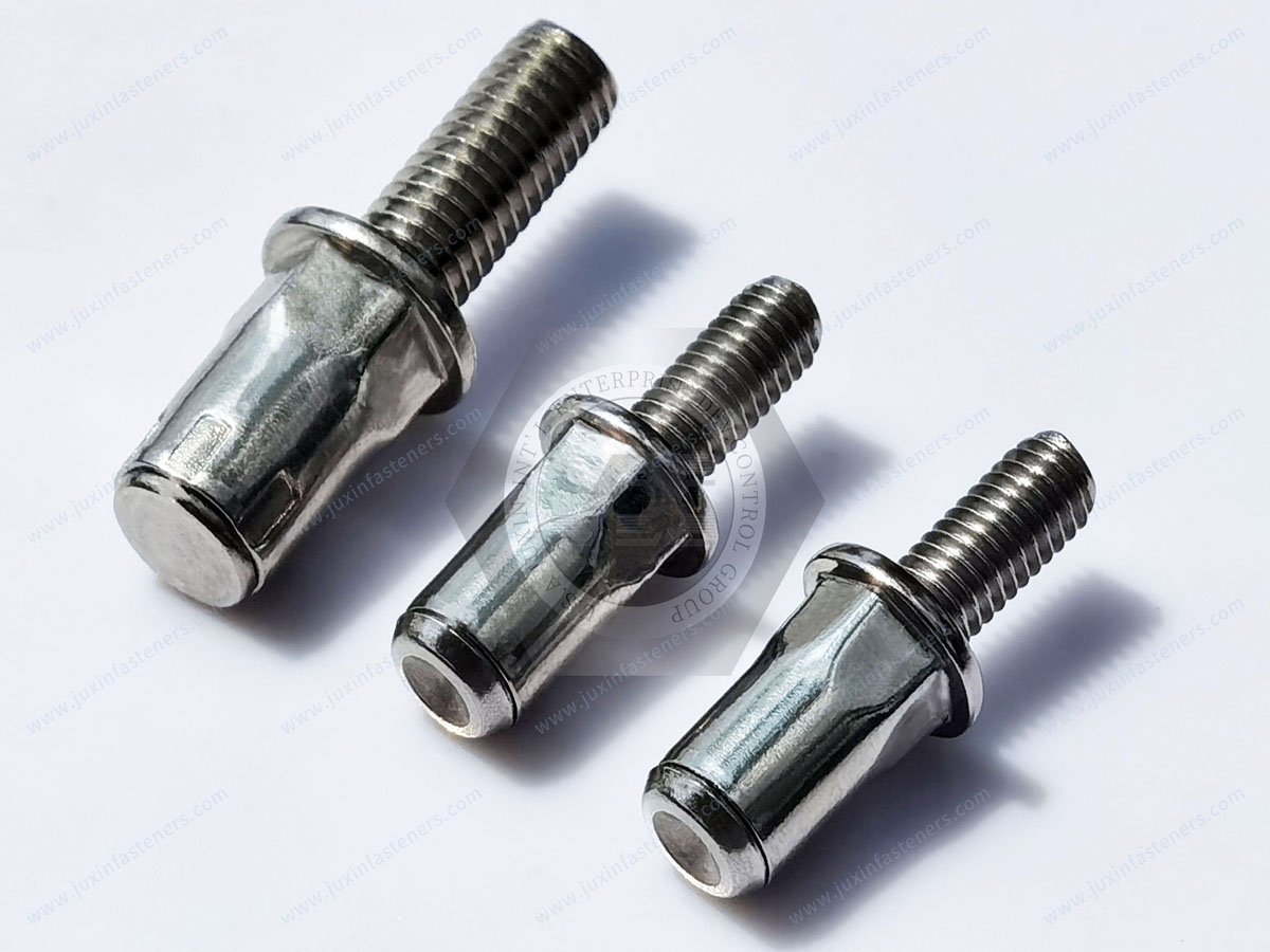
Burrs around the mounting hole can affect insertion and installation.
A significant burr may:
Change effective hole geometry
Interfere with seating
Affect surface contact
Produce inconsistent installation
The drawing or process specification should define the acceptable hole condition when required.
Some blind threaded stud applications require resistance to rotation when the mating nut is tightened.
This is particularly relevant where:
Assembly torque is significant
The stud is used as a fixed mounting point
The component is repeatedly serviced
Vibration is present
Anti-rotation may be supported by:
Knurled body geometry
Hex or partially hexagonal geometry
Other product-specific mechanical features
The appropriate design depends on the parent material and hole.
A knurled body provides a non-smooth interface around the stud.
During installation, the knurled geometry interacts with the parent material around the hole.
This can increase resistance to rotational movement compared with a smooth cylindrical interface, depending on the complete joint configuration.
However, knurling should not be treated as an automatic guarantee of a specified torque-out value.
The result depends on:
Knurl geometry
Hole diameter
Parent material
Panel thickness
Installation condition
Applied torque
A hexagonal or partially hexagonal body provides another anti-rotation approach.
The non-circular geometry interacts with the receiving hole and parent material.
Hex geometry can be useful where rotational stability is important.
The actual performance still depends on the product geometry and receiving panel.
Therefore, “hex” should be understood as a design feature, not a universal performance rating.
Spin-out occurs when the installed stud rotates within the parent panel instead of remaining rotationally stable.
Potential contributing factors include:
Oversized hole
Inappropriate anti-rotation geometry
Parent material characteristics
Incorrect installation
Excessive assembly torque
Local panel deformation
This is why a product should be tested under the actual assembly conditions where torque resistance is important.
Torque-out evaluation examines the rotational resistance of the installed stud under applied torque.
Torque-out is different from:
Pull-out
Pull-through
Shear
Stud tensile failure
A complete engineering validation plan should select the test mode that corresponds to the actual expected loading.
Pull-out refers to axial loading that attempts to remove the installed stud from the parent material.
The result may be influenced by:
Parent material
Stud geometry
Grip
Flange geometry
Hole condition
Installation quality
Pull-out should therefore be measured using a defined test configuration rather than inferred from thread size.
Pull-through is another potential failure mechanism in sheet-metal fastening.
The parent panel may deform or fail around the installed component.
The relevant resistance depends on the geometry and mechanical properties of the panel and fastening component.
This is why the sheet-metal structure must be included in engineering validation.
Where the mounted component applies a lateral load, shear behavior may become important.
Examples include:
Brackets
Equipment supports
Cable supports
Interior automotive components
Electrical mounting assemblies
The engineer should consider the stud cross-section, projection, panel stiffness and load direction.
The flange or head provides an important interface with the front surface of the parent panel.
Relevant characteristics may include:
Flange diameter
Flange thickness
Bearing area
Head profile
Surface condition
The flange should be evaluated together with the parent panel.
A larger flange is not automatically equivalent to higher overall joint strength.
The body geometry controls how the blind side deforms during installation.
Possible designs include:
Smooth cylindrical body
Knurled body
Hexagonal body
Other application-specific configurations
The geometry should be matched to:
Hole
Panel material
Panel thickness
Grip
Required rotational resistance
Carbon steel can be suitable for many general industrial and automotive fastening applications.
Potential advantages include:
Mechanical strength
Cost efficiency
Broad industrial use
The actual material grade should be specified according to the customer drawing and applicable product requirements.
A generic statement such as “carbon steel equals high strength” is insufficient for controlled engineering procurement.
Stainless steel may be considered when corrosion resistance or material compatibility is important.
Potential applications include:
Outdoor equipment
Industrial machinery
Electrical enclosures
Corrosion-exposed equipment
Appearance-sensitive assemblies
The specific stainless steel grade should be confirmed against the actual product specification.
Where applicable, ISO 3506 may be relevant to stainless steel fasteners within its defined scope, but it should not be used as a blanket standard for every blind threaded stud configuration.
Aluminum blind threaded studs may be considered for weight-sensitive assemblies.
Potential applications include:
Electronics equipment
Lightweight enclosures
Portable machinery
Aluminum structures
Selected automotive components
The lower density of aluminum can reduce component mass, but material selection must also consider:
Joint loading
Parent panel strength
Wear
Corrosion compatibility
Thermal expansion
Installation behavior
Using compatible aluminum materials can reduce some dissimilar-metal concerns.
However, the joint still needs to be evaluated for:
Material strength
Local deformation
Thread behavior
Installation consistency
Environmental exposure
Material compatibility should therefore be considered alongside mechanical performance.
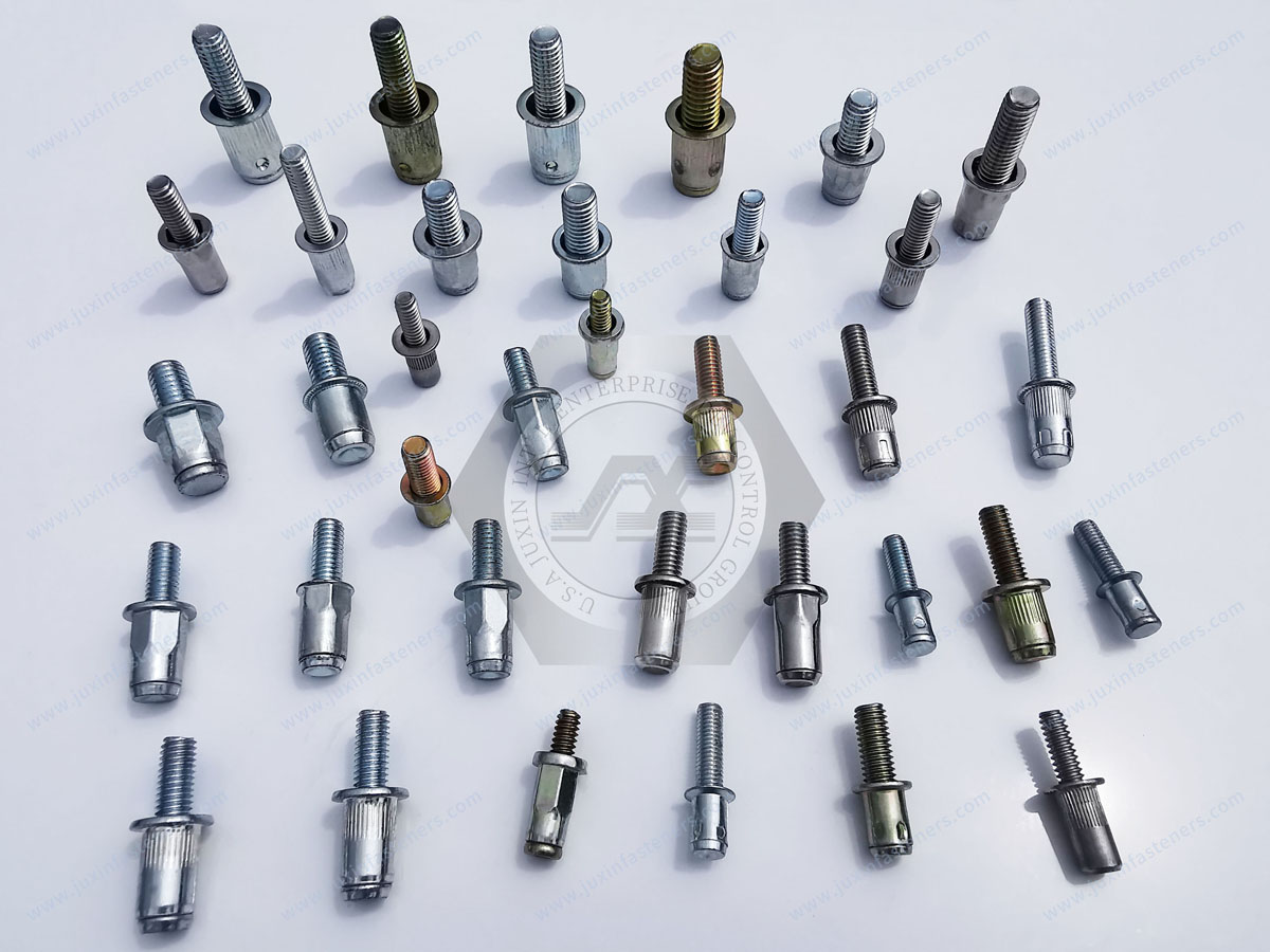
Steel and aluminum combinations require particular attention to galvanic compatibility in environments where moisture or other electrolytes are present.
The engineer should consider:
Surface treatment
Electrical contact
Moisture exposure
Joint geometry
Service environment
A surface coating can form part of the corrosion-control strategy but should not be treated as a universal guarantee.
Surface finish should be selected according to the actual service environment.
Possible finish categories may include:
Zinc-based coatings
Zinc-nickel systems
Black oxide where appropriate
Stainless steel passivation
Other application-specific finishes
The finish specification should identify the required system rather than simply stating “corrosion resistant.”
Zinc-based finishes are widely used for carbon-steel fasteners in general industrial applications.
When specifying a zinc finish, procurement should identify the required:
Coating system
Appearance
Corrosion requirement
Thickness where applicable
Environmental restrictions
The exact finish must be confirmed against the customer's specification.
Zinc-nickel coatings may be considered where enhanced corrosion performance is required for particular applications.
However, corrosion performance should be specified through the customer's actual coating specification and validation method.
A generic statement such as “zinc-nickel provides a guaranteed service life” should be avoided because environmental exposure and assembly conditions vary.
Passivation is a surface-treatment process used to improve the corrosion behavior of suitable stainless steel surfaces.
ASTM A967/A967M covers chemical passivation treatments for stainless steel parts.
The applicability of a particular passivation treatment should be confirmed for the material and customer specification.
The stud finish should be considered together with the parent panel.
Examples include:
Zinc-coated steel stud + steel panel
Zinc-based finish + aluminum panel
Stainless steel stud + stainless steel panel
Stainless steel stud + aluminum panel
The correct combination depends on the environment and application.
Blind threaded studs may provide an alternative process sequence where welding would otherwise need to occur before painting or powder coating.
Because installation is mechanical rather than fusion welding, the fastening operation does not introduce welding heat at the installation point.
This can create opportunities to separate:
Sheet fabrication
Surface finishing
Mechanical stud installation
Final component assembly
The actual process sequence must still be validated against coating thickness, hole condition and installation requirements.
Powder coating creates a finished surface that may be sensitive to:
Tool contact
Scratching
Coating thickness
Hole coverage
Local deformation
Where a blind stud is installed after coating, the production team should confirm:
Hole preparation
Coating condition
Tool access
Stud seating
Final surface condition
The ability to install after coating should therefore be treated as an application-specific manufacturing option rather than a universal product guarantee.
Automotive applications may require blind threaded studs for:
Interior brackets
Electrical components
Body-related brackets
Cable supports
Equipment mounting
Sheet-metal assemblies
Automotive applications can also involve vibration, thermal cycling and corrosion exposure.
The fastening specification should therefore be linked to the actual vehicle subsystem and validation requirements.
For related automotive fastening solutions, see Industrial & Automotive Bolts and Nuts.
Electrical cabinets and equipment enclosures often contain thin sheet-metal structures where rear access is restricted.
Blind threaded studs can provide external mounting points for:
Brackets
Covers
Cable-management hardware
Electrical components
Support structures
The selected stud should be evaluated for panel material, finish, installation sequence and required load.
Automation systems frequently contain:
Machine guarding
Equipment panels
Sensor brackets
Cable supports
Control cabinets
Access panels
A blind external-thread fastening point can simplify mounting where one-sided installation is required.
The design should consider service access and repeated assembly cycles where applicable.
HVAC and appliance products commonly use formed sheet-metal structures.
Blind threaded studs may be considered for:
Brackets
Covers
Equipment supports
Internal mounting components
Sheet-metal subassemblies
The correct configuration depends on the actual material, thickness, environment and assembly process.
Electronics equipment may use painted, plated or anodized sheet-metal housings.
Blind threaded studs can provide external mounting points without requiring rear-side access.
For sensitive equipment, engineers should additionally consider:
Electrical continuity
Grounding requirements
Corrosion
Surface finish
Component clearance
Serviceability
A fastening component should not automatically be described as an EMI/RFI or grounding solution unless the specific design has been engineered and validated for that purpose.
Blind threaded studs may be used in selected electric-vehicle components where an external threaded mounting point is required.
Potential applications include:
Brackets
Electrical component mounts
Cable-management assemblies
Enclosure-related components
Support structures
Battery enclosure applications can also involve sealing, electrical isolation and corrosion requirements.
A blind threaded stud should not automatically be considered an IP-rated sealing component.
Where sealing is required, the complete enclosure assembly should be designed and validated against the applicable protection requirements.
For related EV sealed fastening applications, see Closed-End Sealing Blind Rivet Nuts for EV Battery Enclosures.
Weight-sensitive equipment may consider aluminum or other application-specific blind stud materials.
However, aerospace and other highly regulated applications require strict control of:
Material
Traceability
Drawing requirements
Process requirements
Validation
Customer approvals
JUXIN FASTENERS should evaluate such requirements based on the actual customer specification rather than assuming a generic aerospace certification.
Blind threaded studs can be useful in hollow profiles where the rear side is physically inaccessible.
Examples may include:
Tubular frames
Enclosed structural sections
Equipment housings
Formed channels
The internal geometry must provide sufficient clearance for installation.
The engineer should verify:
Access direction
Hole position
Internal obstruction
Tool clearance
Stud length
Installation stroke
The installation tool must match the blind stud design.
Important considerations include:
Tool interface
Stud thread
Installation mechanism
Required stroke
Required force
Accessibility
Manual or automated assembly
Production volume
Tool selection should therefore be based on the actual part and manufacturing process.
Installation stroke describes the controlled movement used to deform the blind side of the stud.
It is a product- and process-specific parameter.
The correct stroke depends on:
Stud geometry
Grip
Parent material
Installation tooling
Too little deformation can result in inadequate engagement.
Excessive deformation may affect the stud or parent material.
Installation force is the mechanical force required during the forming operation.
It is different from installation stroke.
A tool can potentially provide sufficient force but still require incorrect stroke control.
Production validation should therefore consider both variables where applicable.
Installation quality can be affected by:
Hole condition
Stud orientation
Grip
Tool setting
Panel support
Operator technique
Automated process control
For production programs, installation instructions should be based on the approved product and process specification.
Correct seating of the flange against the parent panel is an important visual and functional check.
Potential issues include:
Improper positioning
Panel distortion
Foreign material
Incorrect hole geometry
Incomplete installation
The acceptance criteria should be defined by the drawing or assembly specification.
Stud location relative to the panel edge can affect local mechanical behavior.
The engineer should consider:
Edge distance
Panel thickness
Material ductility
Load direction
Nearby bends
Reinforcements
A universal minimum edge distance should not be assumed without reference to the specific product and application.
Installing a blind stud close to a formed bend can change the local stiffness and deformation behavior.
Designers should identify:
Bend radius
Distance from bend
Panel thickness
Stud orientation
Load direction
For critical applications, prototype testing in the actual geometry is recommended.
Two panels with the same nominal material and thickness can behave differently if their local structures differ.
Examples include:
Flat panel
Ribbed panel
Reinforced panel
Bent flange
Formed channel
The local structure should therefore be considered when evaluating joint performance.
For vibrating equipment, the engineer should evaluate both:
Stud-to-panel rotational stability
Mating nut-to-thread loosening
These are different mechanisms.
Anti-rotation of the blind stud does not automatically prevent the mating nut from loosening.
Where necessary, a suitable locking-nut strategy should be considered.
JUXIN FASTENERS also provides Nylon Insert Locknuts and Self-Locking Fasteners.
Thermal cycling can affect the complete assembly because different materials may expand at different rates.
Potential variables include:
Stud material
Panel material
Mating nut
Coating
Joint preload
Environmental exposure
For automotive and industrial applications, the actual temperature cycle should be included in validation where relevant.
Material and finish should be selected according to the intended environment.
Consider:
Indoor or outdoor exposure
Humidity
Salt exposure
Chemicals
Cleaning agents
Condensation
Dissimilar-metal contact
ASTM B117 can be used as a laboratory salt-spray test method where appropriate, but salt-spray results should not be interpreted as a direct prediction of service life.
Customer procurement specifications may require compliance with environmental regulations such as:
RoHS
REACH
These requirements should be evaluated according to the actual material, coating and customer specification.
Supplier declarations should be based on controlled product and material information rather than blanket statements that are not supported by the relevant documentation.
Dimensional inspection should focus on the characteristics defined by the approved drawing.
Potential inspection characteristics include:
Thread diameter
Thread pitch
Thread length
Overall length
Flange diameter
Flange thickness
Body diameter
Anti-rotation geometry
Critical tolerances
The inspection plan should be appropriate to the product and customer requirement.
External threads can be checked using appropriate dimensional and functional inspection methods.
Depending on the specified thread system, this may include:
Thread gauges
Dimensional measurement
Visual inspection
Functional mating checks
The applicable inspection method should be defined by the drawing and quality specification.
Material verification may be required for OEM programs.
Depending on the customer's requirements, documentation can include appropriate material identification or test documentation.
The specific certificate type should not be assumed.
If a customer requires EN 10204 documentation, the required inspection-document type should be stated explicitly in the purchasing specification.
Traceability requirements vary between customers and industries.
A controlled procurement program may require identification of:
Material batch
Production batch
Lot
Part number
Drawing revision
Surface-treatment batch
The exact traceability level should be established by the customer's quality requirements.
A robust blind threaded stud drawing may need to identify:
Product geometry
Thread specification
Thread length
Overall length
Stud projection
Flange dimensions
Body geometry
Grip range
Material
Surface finish
Applicable standards
Critical tolerances
Functional requirements
Inspection requirements
The drawing should define what is critical to the assembly rather than relying on a generic product description.
A procurement RFQ should normally include:
Approved drawing
Drawing revision
Part number
Annual volume
Forecast
Target application
Material
Surface treatment
Packaging
Quality documentation
Inspection requirements
Sample requirements
Delivery requirements
Change-control expectations
This gives suppliers a controlled basis for quotation.
Supplier development teams may evaluate:
Technical drawing interpretation
Manufacturing process
Material control
Surface-treatment control
Thread inspection
Dimensional inspection
Traceability
Change management
Sample approval
Production consistency
Nonconformance handling
Packaging control
These are supplier-qualification considerations and should be aligned with the customer's procurement system.
One of the most common mistakes in blind stud sourcing is treating thread size as the complete product definition.
For example:
M6 ≠ complete blind threaded stud specification
A controlled specification may instead look conceptually like:
M6 + pitch + thread length + stud projection + flange + body geometry + grip + hole + material + finish
This approach greatly reduces ambiguity during OEM sourcing.
Another important principle is:
Grip range should be selected from the real material stack, not from nominal sheet thickness alone.
If a component is installed over multiple layers, the supplier needs the actual minimum and maximum condition.
This helps prevent incorrect deformation positioning and inconsistent installation.
The stud cannot be separated from the receiving hole.
A useful engineering relationship is:
Stud geometry ↔ Hole geometry ↔ Parent material ↔ Installation process
Changing any one of these variables can affect the installed joint.
This is why a blind stud should not be selected by visual similarity to another product.
Knurling or hex geometry can support anti-rotation.
However:
Anti-rotation performance = stud geometry + hole condition + parent material + installation condition + applied torque
This is more useful than simply labeling a product “high torque.”
For critical assemblies, the complete installed joint should be validated.
Installation stroke describes movement.
Installation force describes the force required during that movement.
They should not be treated as interchangeable specifications.
For production engineering, the tool setup should be established around the actual blind stud, grip and parent material.
A blind stud can have the correct nominal thread but still be unsuitable if its projection is incorrect.
The engineer should calculate the complete stack:
Panel + bracket + washer + required nut engagement + clearance
This prevents both insufficient thread engagement and unnecessary protrusion.
A larger or stronger stud does not automatically create a stronger assembly.
Potential limiting interfaces include:
Stud
Thread
Mating nut
Parent panel
Blind-side deformation
Hole
Bracket
Local panel structure
This is particularly important when engineers are replacing a welded stud or another established fastening method.
A blind threaded stud can meet its dimensional requirements and still fail in an incorrectly designed assembly.
Therefore:
Part inspection ≠ joint validation
Joint validation should reproduce the actual:
Stud
Hole
Parent material
Grip
Installation process
Mating hardware
Loading condition
This distinction is valuable for both engineering and supplier development teams.
A practical selection sequence is:
1. Define the application
2. Determine whether an external thread is required
3. Identify parent material
4. Identify minimum and maximum stack-up
5. Define hole diameter and tolerance
6. Select thread size and pitch
7. Define stud projection and thread length
8. Determine anti-rotation requirement
9. Select material
10. Select surface treatment
11. Define installation method
12. Confirm mating hardware
13. Define validation requirements
14. Release drawing
15. Request production quotation
This sequence connects engineering selection directly to procurement.
For an OEM RFQ, provide:
2D drawing
3D model where available
Part number
Drawing revision
Thread size
Thread pitch
Thread system
Thread length
Stud projection
Overall length
Flange dimensions
Body geometry
Anti-rotation requirement
Parent material
Panel thickness
Minimum stack-up
Maximum stack-up
Hole diameter
Hole tolerance
Hole-making method
Surface finish
Environmental conditions
Mating nut
Assembly torque
Installation tool information
Prototype quantity
Annual volume
Packaging requirements
Inspection requirements
Documentation requirements
The more complete the RFQ, the less likely the quotation will be based on assumptions.
JUXIN FASTENERS supports B2B sourcing of blind threaded studs and related fastening components based on customer-specific engineering requirements.
For an OEM program, the evaluation can begin with the actual drawing and application information.
The key objective is to align:
Product geometry
Thread
Material
Surface treatment
Parent panel
Hole
Grip
Installation
Mating hardware
Validation
This approach supports the requirements of design engineering, purchasing, supplier development and supply chain teams.
Blind threaded studs are often part of a broader fastening program.
Depending on the assembly, related requirements may include:
Blind rivet nuts
Sealing blind rivet nuts
Self-clinching fasteners
Weld fasteners
Locking nuts
High-strength bolts
Stainless steel fasteners
CNC-machined components
Plastic fasteners and components
For applications requiring internal threaded fastening, see Blind Rivet Nuts Engineering Solutions.
For EV enclosure applications involving sealed blind fastening, see Sealing Blind Rivet Nuts for EV Battery Enclosures.
For related high-strength hardware requirements, see High-Strength Bolts and Nuts.
The correct blind threaded stud is selected by the complete joint requirement, not by nominal thread size alone.
The essential principles are:
Blind threaded studs create external male threads through single-sided mechanical installation.
They are different from blind rivet nuts, which create internal female threads.
Thread diameter does not define the complete stud.
Thread length and stud projection should be specified separately.
Grip range must reflect the actual stack-up.
Hole diameter and hole quality are critical.
Anti-rotation geometry should match the parent material and hole.
Spin-out, pull-out, pull-through and shear are different failure modes.
Installation stroke and installation force are separate process variables.
Material and surface treatment should be selected for the complete environment.
The mating nut and mounted component are part of the joint.
Coated-panel installation may provide process-sequencing advantages, but the actual assembly must be validated.
International standards should only be referenced where their scope applies to the specific product.
Component inspection does not replace application-level joint validation.
A drawing-controlled RFQ reduces technical ambiguity and procurement risk.
If you are developing a blind threaded stud, blind rivet stud, pull-up stud or custom external-thread fastening solution, send JUXIN FASTENERS your engineering and sourcing requirements.
For technical evaluation, please include your:
2D drawing
3D model where available
Thread specification
Stud projection
Parent material
Panel thickness
Stack-up
Hole diameter
Anti-rotation requirement
Surface finish
Mating nut
Installation requirements
Environmental conditions
Expected production volume
Email: info@juxinfasteners.com
JUXIN FASTENERS can review the available information and identify the product and technical parameters that need to be confirmed for sampling, validation and OEM production sourcing.
For broader external-thread fastening requirements, also see Blind Threaded Studs: Cold-Mechanical Installation & External Thread Solutions.
 MORE NEWS

Sep. 25, 2026

Sep. 25, 2026

Sep. 25, 2026
Contact Us
Tel.:
+86 020 8621 0320
+86 020 3121 6067
E-mail:
Technical Support:
Navigation
SEND INQUIREY