
Call Us
+86 136 6007 9809
Call Us
+86 136 6007 9809

Aug. 11, 2026
Bolt Clearance Hole Sizes and Threaded Pilot Hole Design Solutions
Engineering Standards for Precision Assembly and OEM Manufacturing | JUXIN FASTENERS
In mechanical and structural design, two seemingly minor details often determine whether an assembly succeeds or fails:
Bolt clearance hole size
Threaded pilot (tapping) hole diameter
Incorrect sizing can lead to:
Assembly jamming or misalignment
Reduced joint strength
Preload inconsistency
Structural loosening or fatigue failure
This engineering guide explains how to correctly determine hole sizes based on international standards such as ISO 273 (clearance holes for bolts), ISO 724 / ISO 965 (metric threads), and DIN 13 (thread profiles), providing practical solutions for OEM engineers, designers, and procurement teams.
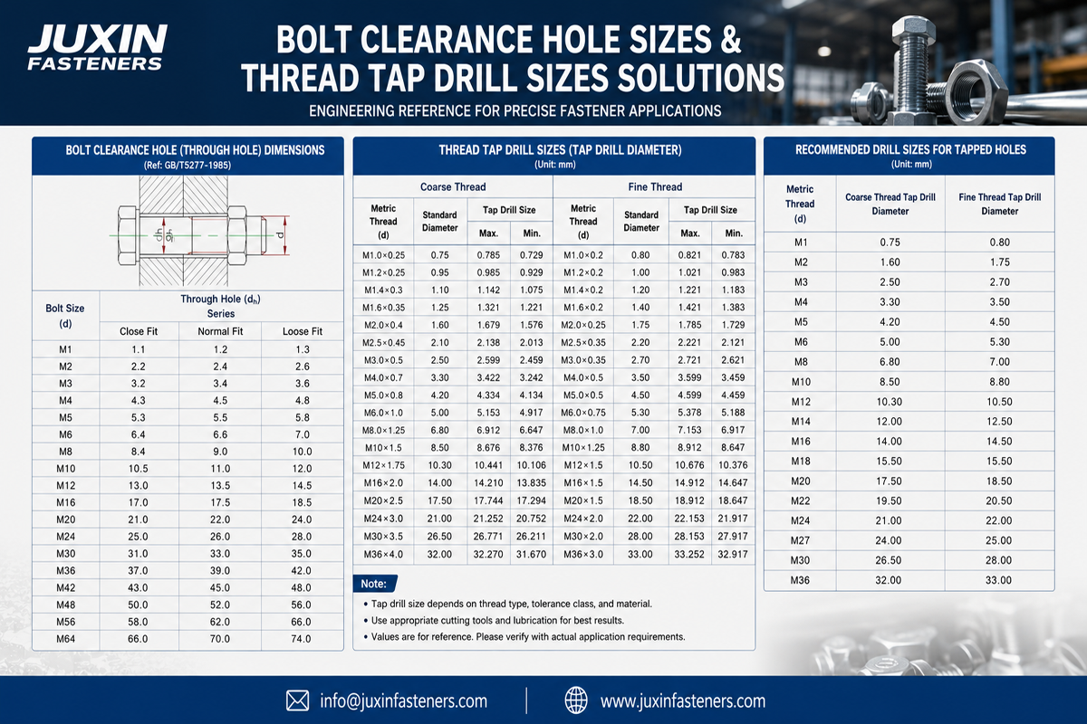
1. Bolt Clearance Hole Size Selection (ISO 273 Standard System)
1.1 Engineering Principle of Clearance Hole Design
The purpose of a bolt clearance hole is to:
Allow smooth bolt insertion
Maintain positional accuracy
Control assembly tolerance stack-up
Ensure load transfer consistency in bolted joints
According to ISO 273 (Clearance holes for bolts and screws), clearance holes are classified into three main fit categories.
1.2 Close-Fit Clearance Hole (Precision Positioning Type)
Design concept:
Minimal clearance to ensure alignment and positioning accuracy.
Typical clearance:
Hole diameter = nominal bolt diameter + 0.1 to 0.3 mm
Examples:
M8 bolt → Ø8.1 mm hole
M10 bolt → Ø10.2 mm hole
Applications:
Precision machinery assemblies
Positioning near dowel pins
Structural alignment-critical joints
Engineering characteristics:
High positional accuracy
Requires precise drilling or reaming
Limited assembly tolerance
1.3 Normal Clearance Hole (Standard Industrial Fit)
Design concept:
Balanced between manufacturability and assembly tolerance.
Typical clearance:
Hole diameter = nominal + 0.4 to 0.8 mm
Examples:
M6 → Ø6.6 mm
M8 → Ø9.0 mm
M12 → Ø13.0 mm
Applications:
General mechanical assemblies
OEM production lines
Steel structures and equipment frames
Engineering characteristics:
Compatible with standard drilling processes
Absorbs normal machining deviation (±0.2 mm)
Most widely used ISO 273 category
1.4 Large Clearance Hole (Adjustment Fit Type)
Design concept:
Allows installation flexibility and positional adjustment.
Typical clearance:
Hole diameter = nominal + 1.0 to 1.5 mm
Examples:
M8 → Ø10 mm
M12 → Ø13.5 mm
Applications:
Anchor bolt installations
Large sheet metal structures
Field assembly systems
Engineering considerations:
Requires oversized washers (ISO 7089 / ISO 7090)
Prevents washer pull-through or embedment
Enables tolerance compensation during installation
1.5 Thickness Adjustment Rule (Engineering Practice)
Plate thickness > 20 mm → use lower clearance range
Thin plates → use upper clearance range
This ensures stability against:
Hole misalignment
Thermal deformation
Manufacturing variation
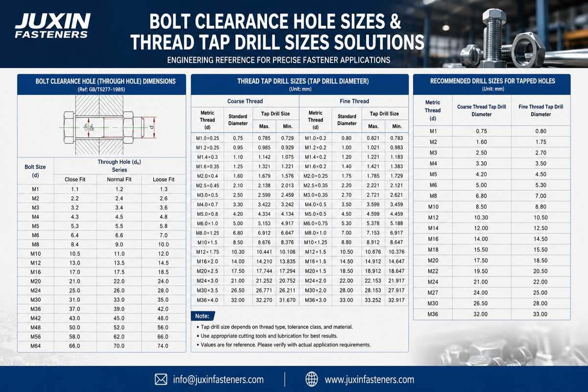
2. Threaded Pilot Hole Size Design (ISO 724 / ISO 965 System)
2.1 Engineering Principle of Thread Engagement
The pilot hole (tapping hole) directly determines:
Thread engagement strength
Torque required for tapping
Risk of thread stripping or tap breakage
According to ISO 724 (metric thread basic dimensions) and ISO 965 (tolerance system), the optimal thread engagement ratio is:
75% – 85% thread height engagement
2.2 Standard Pilot Hole Calculation Formula
Basic engineering formula:
Pilot hole diameter = Major diameter − Pitch
This applies to ISO metric coarse threads.
2.3 Standard Examples (ISO Metric Coarse Threads)
Thread Size | Pitch | Pilot Hole Diameter |
M6 | 1.0 mm | Ø5.0 mm |
M8 | 1.25 mm | Ø6.7 mm |
M10 | 1.5 mm | Ø8.5 mm |
2.4 Material-Based Adjustment Strategy
Stainless steel / Titanium alloys (ISO high-strength machining materials)
Increase hole diameter by 0.1–0.2 mm
Reduces tapping torque
Prevents tool breakage
Example:
M8 stainless steel → Ø6.8 mm
Soft materials (Aluminum, copper, plastics)
Reduce hole diameter by ~0.1 mm
Improves thread grip strength
Prevents stripping during repeated assembly
Example:
M6 ABS plastic → Ø4.9 mm
2.5 Fine Thread Pilot Hole Design
Same formula applies using fine pitch:
Example:
M8×1.0 → Ø7.0 mm pilot hole
Fine threads provide:
Higher preload control
Better vibration resistance
Improved sealing performance
2.6 Blind Hole Depth Requirement (Critical Design Rule)
For blind threaded holes:
Minimum depth = effective thread depth + 2–3 × pitch
Purpose:
Accommodate tap chamfer
Prevent bottoming damage
Avoid tap breakage
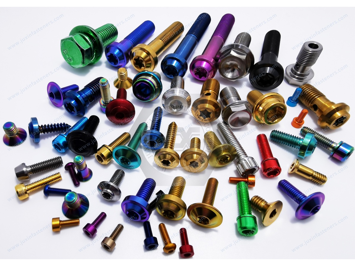
3. Engineering Failure Risks from Incorrect Hole Design
3.1 Undersized holes
Bolt insertion failure
Assembly jamming
Increased installation torque
3.2 Oversized holes
Excessive clearance
Loss of alignment
Reduced preload stability
3.3 Incorrect tapping hole size
Thread stripping
Tap breakage
Reduced joint strength
4. Engineering Selection Logic (Practical Decision Flow)
Step 1: Define assembly purpose
Positioning → Close-fit hole
General assembly → Normal clearance
Adjustable field installation → Large clearance
Step 2: Define material type
Steel / aluminum → standard ISO formula
Stainless steel → enlarge hole slightly
Plastics → reduce hole slightly
Step 3: Define strength requirement
High strength (ISO 898-1 bolts) → tighter control
Non-critical joints → standard ISO 273 clearance
Step 4: Define production method
CNC precision machining → close-fit
Mass production drilling → normal fit
Field assembly → large clearance
5. Relevant International Standards (ISO / DIN System)
ISO 273 – Clearance holes for bolts and screws
ISO 724 – Basic dimensions of metric threads
ISO 965 – Thread tolerance system (6H / 6g fits)
ISO 898-1 – Mechanical properties of fasteners
DIN 13 – Metric thread profile standard
ISO 7089 / ISO 7090 – Flat washers for large clearance holes
6. Application in OEM Engineering Industries
Correct hole design is critical in:
Automotive chassis and body assembly
Construction steel structures
Industrial machinery frames
Wind energy equipment
Electrical enclosures and cabinets
JUXIN FASTENERS supports OEM customers with:
Precision fasteners (ISO/DIN compliant)
Engineering fastening system solutions
Anti-loosening assembly design support
Threaded component optimization guidance
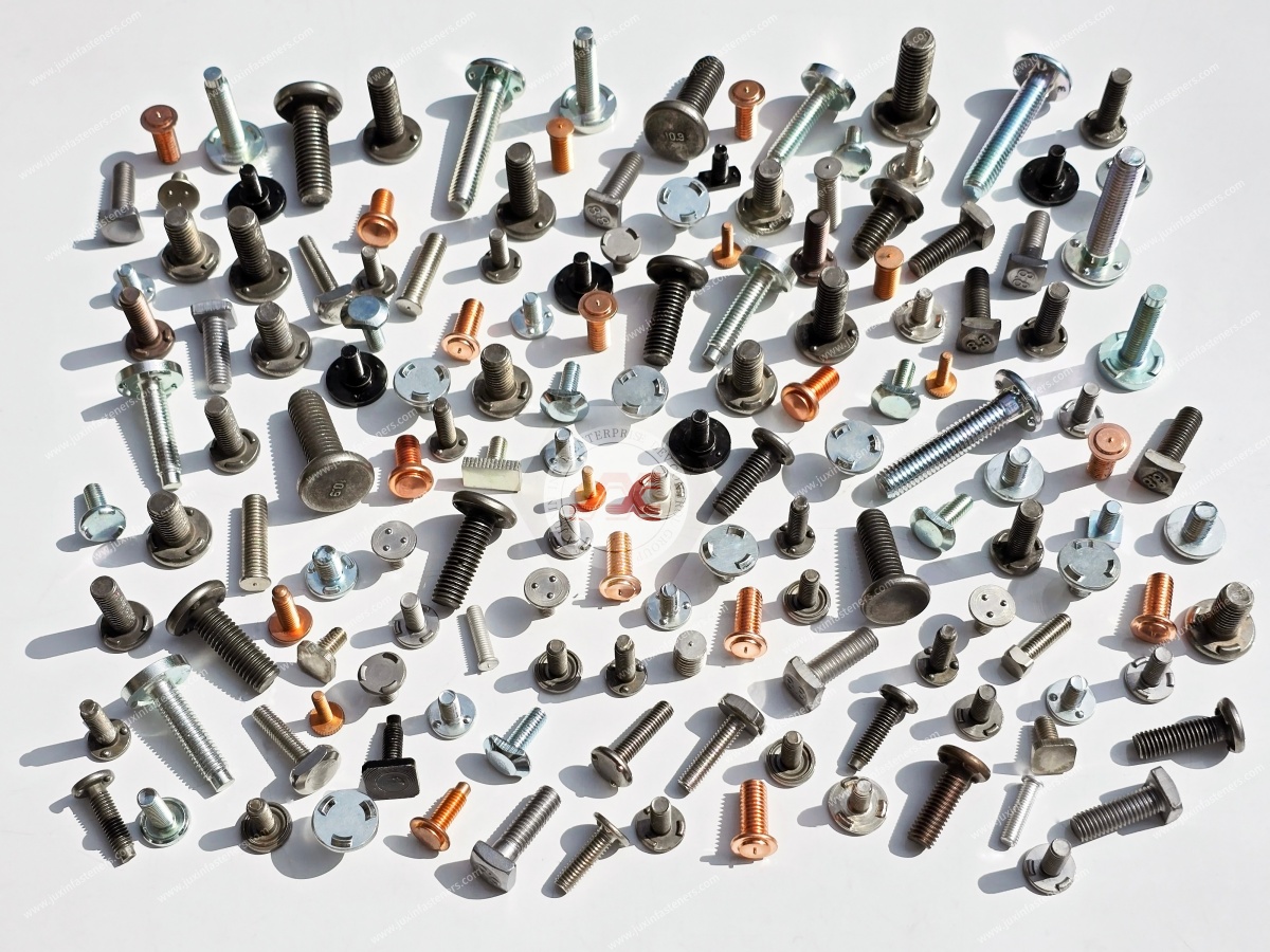
7. Conclusion: Why Hole Design Is a Core Engineering Parameter
Bolt clearance holes and threaded pilot holes are often underestimated, yet they directly determine:
Assembly efficiency
Structural reliability
Load transfer stability
Long-term fatigue performance
By following ISO 273, ISO 724, and ISO 965 standards, engineers can ensure:
Smooth assembly
Controlled tolerance stack-up
Reliable mechanical performance
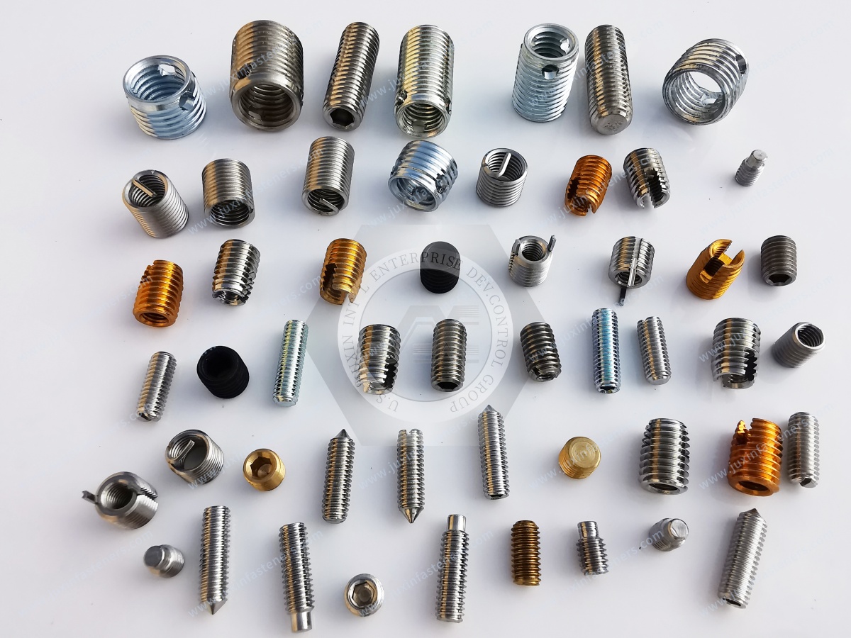
JUXIN FASTENERS Engineering Support
JUXIN FASTENERS provides precision-engineered fastening solutions for global OEM industries:
ISO / DIN standard bolts and screws
Precision nuts and washers
Threaded fastening system optimization
Custom engineering fastening solutions
https://www.juxinfasteners.com
info@juxinfasteners.com
 MORE NEWS

Sep. 27, 2026

Sep. 27, 2026

Sep. 27, 2026
Contact Us
Tel.:
+86 020 8621 0320
+86 020 3121 6067
E-mail:
Technical Support:
Navigation
SEND INQUIREY