
Call Us
+86 136 6007 9809
Call Us
+86 136 6007 9809

Mar. 29, 2023
In modern automotive, aerospace, medical, industrial equipment, and consumer electronics design,
transitioning from metallic housings to lightweight thermoplastics such as PA66, PBT, ABS, Polycarbonate (PC),
and other engineering polymers is increasingly common for mass reduction, electrical insulation, corrosion resistance, and structural optimization.
However, directly tapping internal threads into engineering plastics can create limitations when the joint must withstand repeated assembly, vibration,
thermal cycling, or long-term mechanical loading. Thread stripping, polymer creep, stress relaxation, reduced clamping force, and dimensional changes can become significant design concerns.
Threaded inserts for plastics bridge this gap by introducing a metallic internal thread into a polymer component.
The insert provides a more durable and reusable threaded interface while allowing the surrounding plastic component to remain lightweight.
Depending on the plastic material, component geometry, production volume, and required mechanical performance,
designers may select self-tapping inserts, press-in inserts, press-fit inserts, heat-set inserts, ultrasonic inserts, or molded-in threaded inserts.
This technical guide provides design engineers, mold designers, manufacturing engineers, molders, procurement specialists, and strategic sourcing teams with a practical framework covering:
Mechanical Selection Criteria: Evaluating self-tapping, press-in, heat-set, ultrasonic, and molded-in insert architectures according to the polymer,
loading condition, production process, and required retention performance.
Polymer Boss Design Mechanics: Calculating practical relationships between insert diameter, engagement length, boss diameter, wall thickness, hole geometry, and installation force.
Material Selection: Comparing brass threaded inserts, aluminum threaded inserts, steel inserts, and stainless steel inserts for different thermal, corrosion, weight, electrical, and mechanical requirements.
Installation Engineering: Understanding pilot-hole preparation, heat installation, press installation, self-tapping installation, molded-in placement, and the risks of excessive installation force.
Quality & Verification: Using dimensional inspection, torque testing, pull-out testing, cross-sectional inspection, and application-specific validation to verify insert retention.
Industrial Application Selection: Matching plastic threaded inserts with automotive electronics,
EV systems, electrical equipment, telecommunications, medical equipment, industrial machinery, and consumer products.
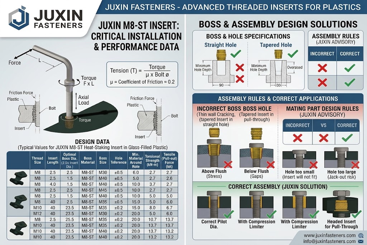
Selecting the correct thread insert material and manufacturing specification is essential for preventing thread damage, galvanic corrosion, excessive insertion force, polymer cracking, and long-term joint failure.
For plastic threaded inserts, it is important to distinguish between:
The standard governing the metal material
The standard governing the internal thread
The standard governing the external insert geometry
The standard governing the surface treatment
The customer drawing or manufacturer's specification governing the finished insert
Not every threaded insert has one universal ISO or DIN product standard covering the complete component. For this reason, engineering drawings should define the insert geometry, material, thread size, tolerance, surface finish, and required mechanical performance rather than relying on a material standard alone.
| Standard / Material Grade | International / Industry Reference | Chemical / Metallurgical Profile | Key Engineering Properties | Industrial Application Suitability |
|---|---|---|---|---|
| Free-Cutting Brass | ASTM B16 / UNS C36000; EN 12164 CW603N may be used as a material reference where applicable | Copper-zinc alloy with lead content characteristic of free-cutting brass grades | Excellent machinability, good electrical conductivity, good thermal conductivity, suitable for heat staking, ultrasonic insertion, and many molded-in applications | Electronics housings, automotive electrical enclosures, sensors, terminal components, fluid-related assemblies |
| Aluminum Alloys | ASTM B211/B211M provides requirements for certain aluminum and aluminum-alloy bar, rod, and wire products; final insert alloy should be specified by drawing | Aluminum alloy selected according to required strength, weight, corrosion behavior, and manufacturing process | Low density, high strength-to-weight ratio, useful where weight reduction is important | Aerospace components, lightweight electronics, EV modules, portable equipment, aluminum-plastic assemblies |
| Stainless Steel | Stainless steel grade should be specified according to application; ISO 3506 is a major reference for corrosion-resistant stainless steel fastener mechanical properties where its scope applies | Austenitic, martensitic, ferritic, or duplex stainless steel depending on application | High corrosion resistance and good long-term dimensional stability; grade selection depends on environment and required properties | Medical equipment, food-processing machinery, marine equipment, outdoor electronics, chemical environments |
| Carbon / Alloy Steel | EN ISO 898-2 and related fastener standards may be relevant to nut-type mechanical properties where applicable; insert geometry and heat treatment should be specified separately | Carbon or alloy steel selected for strength, hardness, wear resistance, and forming/machining requirements | High mechanical strength, high wear resistance, suitable for demanding mechanical joints | Industrial machinery, heavy equipment, structural covers, high-load plastic assemblies |
For procurement teams, an important distinction is that a material specification such as ASTM B16, ASTM B211/B211M, or a stainless-steel grade does not automatically certify a finished threaded insert.
A complete procurement specification should identify:
Insert type
Internal thread size and tolerance
External diameter
Insert length
External retention geometry
Material grade
Heat treatment where applicable
Surface treatment
Installation method
Required pull-out performance
Required rotational torque
Environmental requirements
Inspection requirements
This approach provides a much stronger engineering and purchasing specification than simply specifying “brass insert” or “steel insert.”
Choosing the appropriate plastic threaded insert installation method depends on production volume, polymer matrix, component geometry,
wall thickness, required mechanical load capacity, assembly equipment, and whether the component will require repeated service.
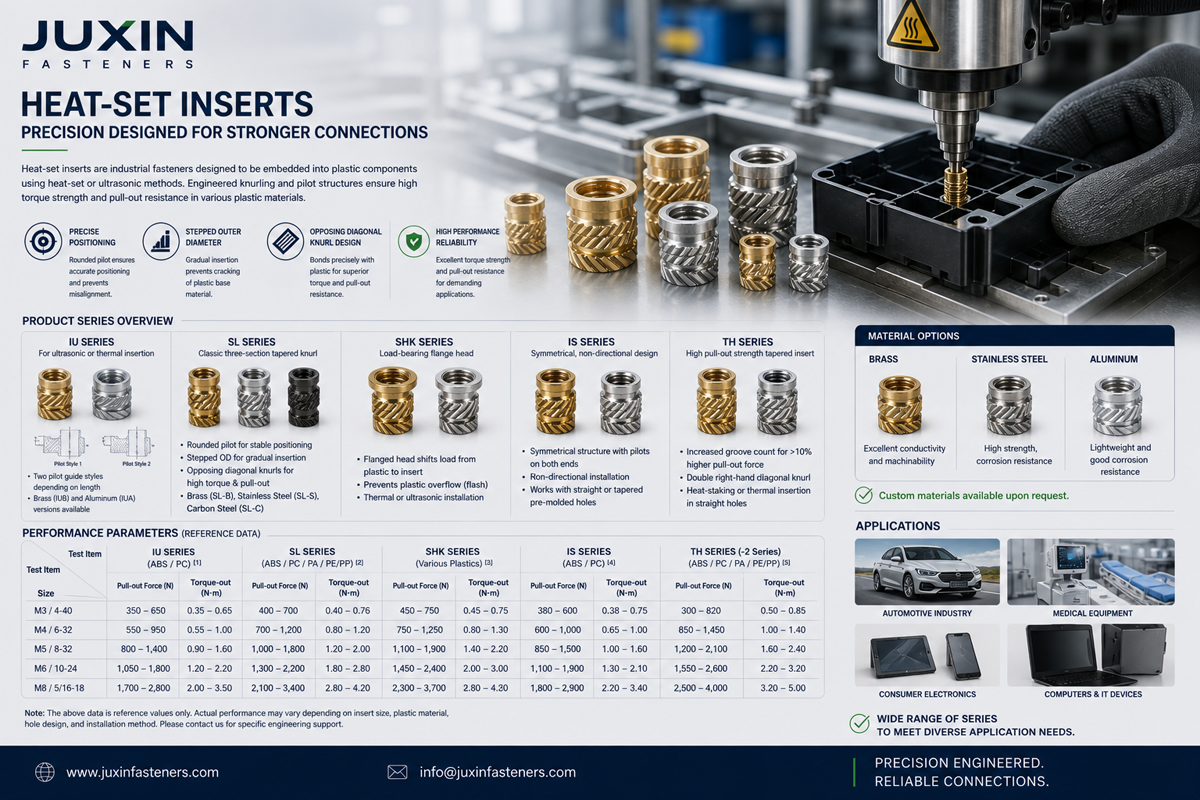
The main architectures include self-tapping inserts, press-in inserts, press-fit inserts, heat-set inserts, ultrasonic inserts, and molded-in inserts.
+--------------------------------------------------------------------------------------------------+
|                                INSERT ARCHITECTURE COMPARISON                                    |
+-----------------------------+-------------------------------+------------------------------------+
| SELF-TAPPING INSERTS        | PRESS-IN / PRESS-FIT INSERTS | MOLDED-IN / HEAT-SET INSERTS       |
+-----------------------------+-------------------------------+------------------------------------+
| - Post-mold installation    | - Fast mechanical assembly   | - Insert placed before or during   |
| - External cutting thread  | - Knurled external profile   |   the molding / heating process    |
| - Thread-cutting action     | - Diamond / straight knurls | - Strong polymer-to-metal retention|
| - Useful for field/service  | - No thermal installation   | - Suitable for production designs |
+-----------------------------+-------------------------------+------------------------------------+
Self-tapping thread inserts are post-mold fasteners designed for installation into a prepared pilot hole in a plastic component.
Depending on the design, the insert may use external cutting slots, cutting edges, or a thread-forming external profile.
During installation, the external geometry creates or forms the mating structure in the polymer.
This makes self-tapping inserts particularly useful when:
The plastic component is already molded
Post-mold installation is required
Serviceability is important
The design cannot accommodate a molded-in insert
Low-volume or flexible production is required
A stronger reusable internal thread is required than the polymer alone can provide
Thread Mechanics:
A properly selected external thread profile increases the effective polymer engagement area.
For a simplified first-order estimate, pull-out resistance can be related to:
F_pull-out ≈ π × d_ext × L_eng × τ_polymer
Where:
d_ext = effective outer diameter of the insert
L_eng = effective engagement length
τ_polymer = effective shear strength of the surrounding polymer
This relationship is useful for understanding design direction, but it should not replace application-specific validation because actual insert retention depends on external geometry,
polymer grade, fiber orientation, hole size, installation process, temperature, and failure mode.
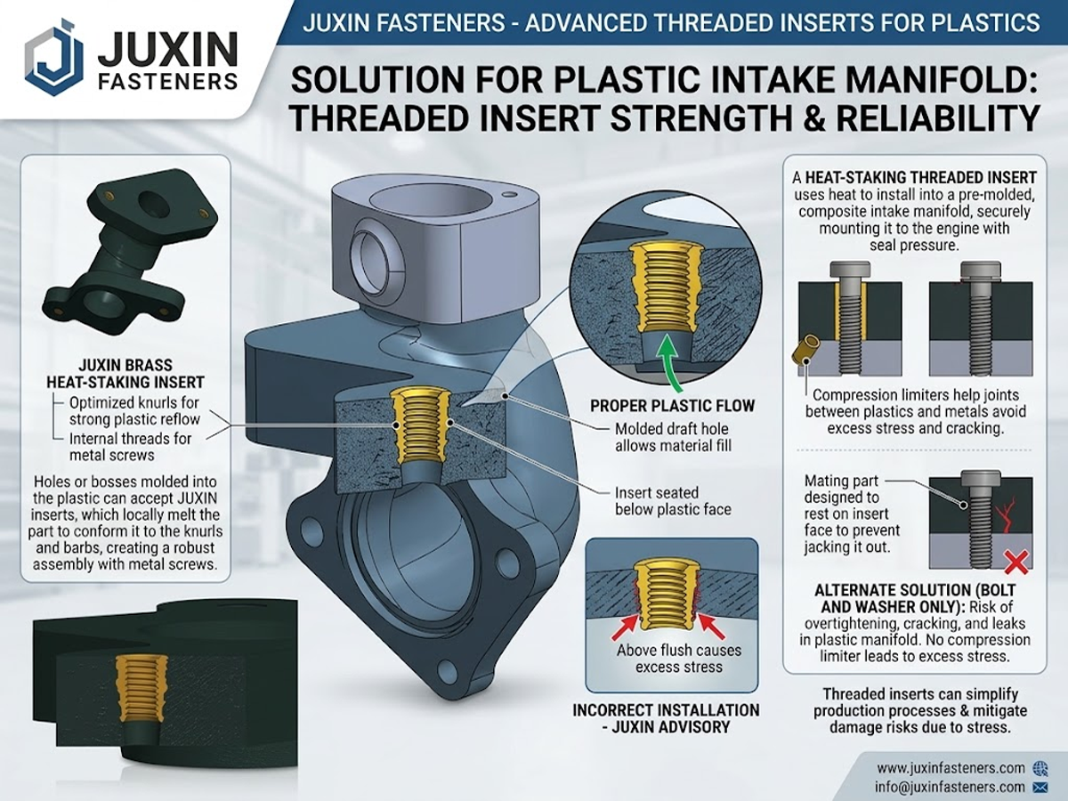
A critical distinction for engineering design is whether the insert cuts the plastic or forms/displaces the material.
Thread-cutting designs remove or displace material to create the external engagement path.
Thread-forming designs primarily displace the polymer and can provide different retention characteristics and installation torque.
The correct choice depends on polymer ductility, boss geometry, pilot-hole tolerance, required installation torque, and the risk of cracking.
Press-in inserts and press-fit inserts are designed for fast mechanical installation after molding.
They may use:
Straight knurls
Diamond knurls
Helical knurls
Serrated external profiles
Grooved or undercut retention features
During installation, the external profile displaces or compresses the surrounding plastic.
These inserts are particularly attractive for high-volume automated assembly because the installation process can be integrated into a production line.
Trade-off:
Press-in inserts eliminate the thermal cycle associated with heat staking and can provide fast installation.
However, the required insertion force must be controlled because excessive force can crack the boss, deform the component, or create excessive residual stress in brittle polymers.
The final design should therefore consider:
Insert outside diameter
Knurl geometry
Pilot-hole diameter
Boss wall thickness
Polymer stiffness
Glass-fiber content
Installation speed
Press force
Temperature
Required pull-out and rotational torque
For thermoplastic components, heat-set inserts are widely used when a controlled thermal installation process is available.
The insert is heated and pressed into the plastic boss. The surrounding thermoplastic softens and flows around the external retention geometry before cooling and solidifying.
Heat-set inserts can provide an efficient combination of:
High pull-out resistance
Good rotational resistance
Controlled installation
Reusable internal threads
High production repeatability
Ultrasonic insertion uses localized mechanical energy to generate heat at the polymer interface and can be useful for automated production.
The correct installation temperature, energy, insertion speed, dwell time, and tooling must be established for the specific polymer and insert geometry rather than applying one universal setting to every plastic.
Molded-in threaded inserts are positioned directly onto core pins or tooling features before polymer injection.
During injection molding, molten resin flows around the insert and encapsulates the external retention geometry.
Molded-in inserts can provide excellent mechanical retention when the insert, mold design, polymer flow, and process parameters are properly matched.
They are especially useful when:
High production volumes justify tooling integration
Insert position must be highly repeatable
Post-mold installation should be eliminated
The assembly requires a permanent metal-to-plastic interface
The insert must withstand repeated assembly cycles
However, molded-in inserts require careful consideration of:
Insert positioning
Polymer flow
Insert temperature
Mold design
Differential thermal expansion
Flash control
Insert movement during injection
Cooling and residual stress
Molded-in inserts should therefore be treated as part of the injection-molding system rather than simply as a conventional fastener.
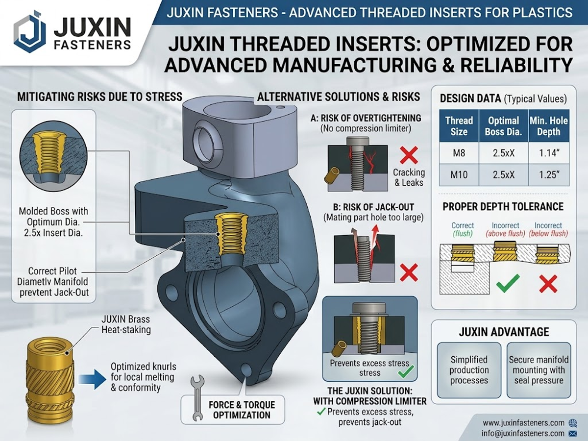
The performance of threaded inserts for plastics depends as much on the surrounding plastic boss as on the metal insert itself.
A strong insert installed into an undersized or poorly designed boss can still fail.
Likewise, increasing insert strength does not necessarily solve a plastic-side failure. In many applications, the surrounding polymer boss, not the metal insert, becomes the limiting component.
The primary design variables include:
Insert outside diameter
Insert length
Effective thread engagement
Boss outside diameter
Boss wall thickness
Pilot-hole diameter
Hole depth
Polymer grade
Glass-fiber content
Installation method
Installation force
Screw tightening torque
Operating temperature
Repeated assembly cycles
                         POLYMER BOSS DESIGN ARCHITECTURE

                             +-------------------+
                             |  Assembly Screw   |
                             +---------+---------+
                                       |
                   Boss Diameter       v        Wall Thickness
                   Design Variable   +-----+    Design Variable
                 |<--------------->|     |<------------------>|
                 +-----------------+     +--------------------+
                 |  ##### |                   | ##### |       |
                 |  ##### |  External Insert  | ##### |       |
                 |  ##### |  Retention Zone   | ##### |       |
                 |  ##### |                   | ##### |       |
                 |        +-------------------+       |       |
                 |  Polymer Matrix  | Insert | Polymer Matrix|
                 |                  | Body   |               |
                 +------------------+--------+---------------+
                              Hole / Boss Geometry
A common failure mode in plastic threaded insert assemblies is jack-out.
Jack-out can occur when the assembly screw reaches the bottom of a blind insert or hole before the joint is fully clamped.
Further tightening can generate axial force against the insert or bottom of the cavity. If the surrounding polymer cannot resist this force, the insert can move upward or the surrounding boss can deform or fracture.
This is particularly important when:
Screw length tolerance is large
Insert length is short
Blind inserts are used
The screw has excessive thread length
Bottom clearance is not controlled
Assembly torque is high
Design principle:
Always provide sufficient clearance between the end of the assembly screw and the bottom of the insert or blind hole under the worst-case dimensional stack-up.
Rather than using one universal depth ratio for every insert design, calculate the required hole depth from:
Insert length
Screw length
Thread engagement
Washer thickness
Component tolerance
Bottom clearance
Assembly condition
For preliminary design, a controlled safety margin beyond the nominal insert length is commonly used, but the final value should be verified against the specific insert manufacturer's drawing and application.
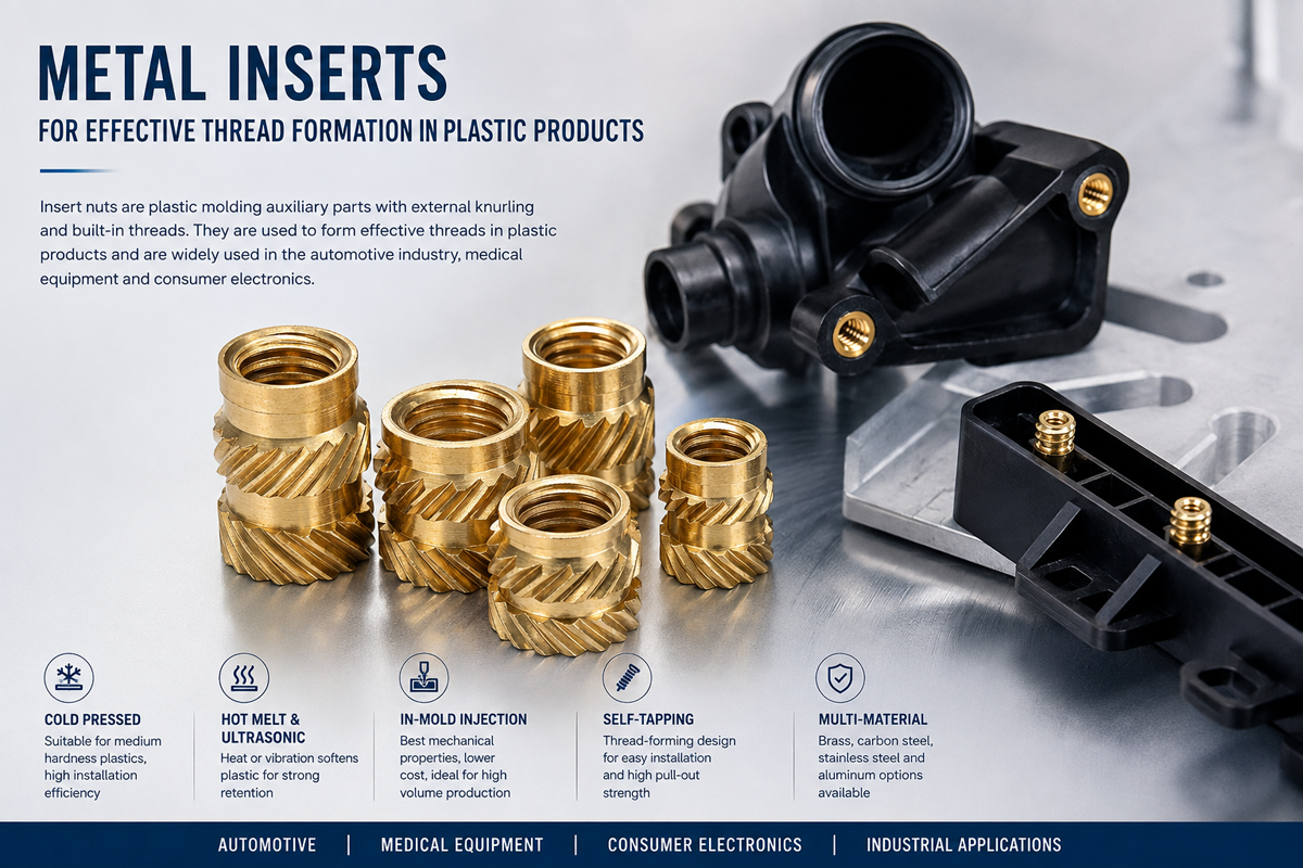
The insert itself may pass pull-out testing while the actual assembly still fails.
This happens because traditional pull-out testing applies an external tensile load to the insert, whereas jack-out can be generated internally by the assembly screw.
Therefore, a complete design validation program should consider both:
External pull-out resistance
Internal screw-to-bottom interference / jack-out resistance
Glass-filled engineering plastics provide higher stiffness and strength but can also change the behavior of the boss during insert installation.
Common materials include:
PA66-GF
PA6-GF
PBT-GF
PC-GF
PPS-GF
Other reinforced engineering thermoplastics
The exact pilot-hole requirement should come from insert geometry, polymer grade, fiber content, molding conditions, and manufacturer recommendations.
Therefore, instead of applying one universal diameter increase to every glass-filled resin, use the following engineering approach:
| Polymer Matrix Filler Percentage | Typical Design Consideration | Design Action Required |
|---|---|---|
| Unfilled / Neat Polymer | Generally more ductile and more tolerant of local deformation | Establish the base pilot-hole diameter from the insert specification and polymer behavior |
| 15% to 30% Glass Fiber | Higher stiffness and potentially greater installation stress | Validate pilot-hole diameter through insertion-force, torque, and boss-crack testing |
| >35% Glass Fiber | Significantly reinforced polymer with reduced local ductility in many grades | Conduct detailed pilot-hole and boss-geometry validation; consider tooling wear and process stability |
For procurement and mold-design teams, the important point is that PA66-GF20 is not automatically equivalent to PBT-GF30, even when both contain a similar percentage of glass fiber.
Polymer chemistry, fiber orientation, molding conditions, moisture content, and temperature can significantly change insert performance.
For materials such as PA6 and PA66, moisture conditioning can also affect dimensional stability and mechanical behavior.
Therefore, when specifying threaded inserts for glass-filled nylon, the validation condition should state whether testing is performed on:
Dry material
Conditioned material
Production-aged components
Elevated-temperature components
Thermally cycled components
This creates a more meaningful engineering specification than testing the metal insert alone.
The plastic boss must provide sufficient material around the insert to resist:
Hoop stress
Radial expansion
Cracking
Pull-out
Rotation
Local deformation
A common preliminary design approach is to make the boss outside diameter significantly larger than the insert outside diameter,
often using a ratio in the approximate range of 2.0 to 3.0 × insert outside diameter as a starting point.
However, this should be treated as a design guideline rather than a universal standard.
The required boss diameter depends on:
Polymer strength
Insert diameter
External retention geometry
Insert length
Screw tightening torque
Installation method
Boss height
Wall thickness
Fiber orientation
Operating temperature
For highly loaded joints, the boss should be validated using physical testing or FEA-supported engineering analysis.
For production plastic components, a molded pilot hole can provide consistent geometry when the injection-molding process is properly controlled.
However, a molded hole is not automatically stronger than a drilled hole in every application.
The final performance depends on:
Mold design
Polymer flow
Cooling
Fiber orientation
Machining quality
Hole tolerance
Surface condition
Residual stress
For prototype or low-volume components, a machined or drilled hole may be appropriate.
For high-volume injection-molded parts, controlling the molded hole geometry can significantly improve assembly repeatability.
Ensuring long-term reliability in high-vibration environments requires more than dimensional inspection of the metal insert.
A complete threaded insert quality control program should evaluate the interaction between the insert and the plastic component.
Important validation methods include:
Dimensional inspection
Internal thread gauge inspection
External diameter inspection
Pilot-hole inspection
Installation-force measurement
Pull-out testing
Rotational torque testing
Screw installation torque testing
Cross-sectional / micro-section inspection
Environmental aging
Thermal cycling
Vibration testing where applicable
+-----------------------------------------------------------------------------------------------+
|                            QUALITY ASSURANCE CROSS-SECTION ANALYSIS                           |
+-----------------------------------------------------------------------------------------------+
|  PASS / ACCEPTANCE CONSIDERATIONS:                                                            |
|  [1] Consistent polymer engagement around the external insert retention geometry.             |
|  [2] No unacceptable voids, cracks, sink-related defects, or incomplete encapsulation.       |
|  [3] Undamaged internal thread geometry with no unacceptable polymer flash.                   |
|  [4] Insert position and perpendicularity remain within drawing requirements.                 |
|  [5] Pull-out and rotational resistance meet the application specification.                   |
|                                                                                               |
|  FAILURE INDICATIONS:                                                                         |
|  [1] Cracks propagating outward from knurl or retention features into the boss wall.          |
|  [2] Significant gaps between the plastic and metallic insert.                               |
|  [3] Insert rotation under the specified assembly torque.                                    |
|  [4] Insert movement or extraction below the required pull-out load.                          |
|  [5] Internal thread damage or polymer contamination of the mating thread.                   |
+-----------------------------------------------------------------------------------------------+
For molded-in, heat-set, and press-in inserts, cross-sectional analysis can reveal failure mechanisms that are invisible from the outside.
A sectioned component can be inspected for:
Polymer flow around the insert
Voids
Incomplete encapsulation
Cracks
Boss wall defects
Insert misalignment
Flash
Local resin degradation
Insufficient external engagement
For high-volume production, this information can be particularly valuable during process validation and tooling development.
Two different mechanical failure modes should be separated:
Pull-out resistance evaluates the axial force required to remove the insert from the plastic.
Rotational torque resistance evaluates the torque required to rotate the insert within the polymer.
A plastic insert joint may have excellent pull-out resistance but inadequate rotational resistance, or the reverse.
Therefore, both tests should be specified when the assembly requires torque-controlled screw installation.
The exact acceptance values should be established from the insert geometry, polymer grade, application load, screw torque, safety factor, and customer engineering requirements.
JUXIN FASTENERS engineers and supplies precision threaded inserts for plastics and other fastening components for applications where polymer components require reliable reusable metal threads.
Typical applications include:
Engine control unit housings
Electronic control modules
Sensor housings
Battery management system enclosures
EV electrical modules
Charging equipment
Automotive interior components
Plastic brackets and covers
These applications may require:
Brass threaded inserts
Aluminum inserts
Stainless steel inserts
Molded-in inserts
Heat-set inserts
High pull-out resistance
High rotational torque resistance
Resistance to vibration and thermal cycling
For automotive and EV applications, validation should consider the actual operating temperature range, thermal cycling, vibration, moisture, and chemical exposure rather than relying on a generic temperature claim.
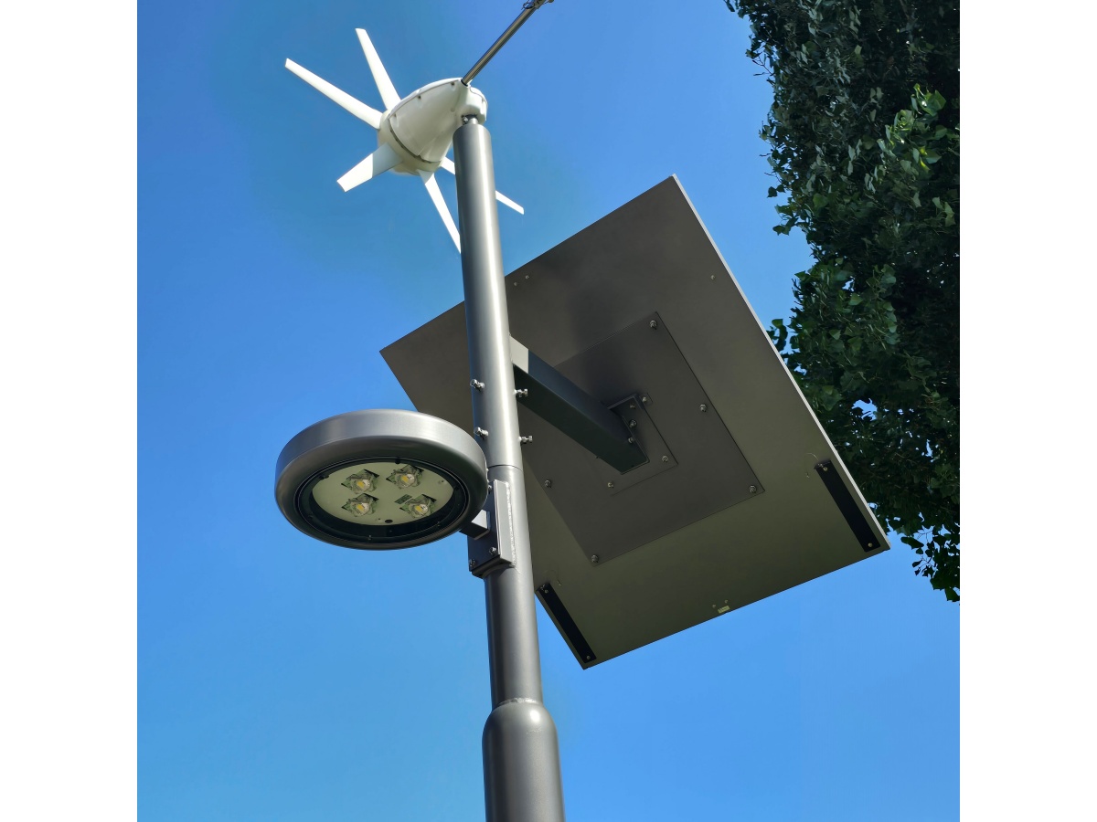
Typical applications include:
Circuit breaker housings
Terminal blocks
Switchgear components
Electrical enclosures
Meter housings
Power-control equipment
Industrial electrical cabinets
Brass threaded inserts are frequently attractive where electrical conductivity, machinability, and heat installation performance are important.
For flame-retardant PA66, PBT, and other engineering plastics, the insert and polymer should be evaluated as a complete assembly.
Applications can include:
Electronic housings
Smart meters
Telecommunications equipment
Consumer appliances
Portable devices
Plastic control panels
Small precision enclosures
Small M1.6, M2, M2.5, and M3 threaded inserts can be considered where compact reusable threads are required, subject to the insert manufacturer's available dimensions and the component's boss geometry.
For compact electronics, the design must also consider:
Installation space
Boss cracking
Alignment
Cosmetic requirements
Electrical insulation
Thread stripping
Repeated service cycles
Plastic housings are widely used in medical and diagnostic equipment because of their weight, corrosion resistance, electrical insulation, and design flexibility.
Potential applications include:
Diagnostic equipment housings
Laboratory equipment
Medical instrument covers
Patient-monitoring equipment
Equipment panels
Disposable or semi-reusable assemblies where applicable
Material selection should consider cleaning chemicals, sterilization requirements, temperature exposure, dimensional stability, and regulatory/customer requirements.
Plastic and composite components are increasingly used in:
Equipment covers
Access panels
Hydraulic control housings
Agricultural equipment
Industrial control systems
Machinery guards
Composite enclosures
For high-load applications, steel self-tapping inserts, stainless steel inserts, or other high-strength insert designs may be considered where the surrounding polymer can support the required load.
The limiting factor should be determined by testing the complete plastic-metal joint rather than evaluating the metal insert in isolation.
To simplify ordering and RFQ generation for procurement managers and supply chain specialists, a complete threaded insert specification should identify the insert geometry, thread, material, finish, installation method, and performance requirements.
                       JUXIN FASTENERS THREAD INSERT RFQ STRUCTURE

   [Insert Type] / [Thread Size] / [Length] / [Material] / [Finish]
                  / [External Geometry] / [Installation Method]

   Example:

   Self-Tapping / M4 / 8 mm / Brass / Plain
   External Cutting Profile / Post-Mold Installation

   Or:

   Press-In / M6 / 10 mm / Brass / Plain
   Diamond Knurl / Automated Press Installation
The example above is a purchasing format rather than a universal JUXIN FASTENERS catalog code. The final part number should be confirmed against the applicable product drawing.
| Ordering Code Parameter | Specification Options | Engineering / Procurement Considerations |
|---|---|---|
| Insert Type | Self-Tapping, Press-In, Press-Fit, Heat-Set, Ultrasonic, Molded-In | Select according to polymer, production process, assembly volume, and required retention |
| Thread Size & Pitch | Metric M2 to M12 or other available sizes; Unified threads where required | Define thread size, pitch, class/tolerance, and mating screw specification |
| Insert Length | Application-specific | Define effective engagement length and available boss height |
| Material | Brass, Aluminum, Carbon Steel, Stainless Steel | Select according to strength, weight, corrosion resistance, electrical requirements, and installation process |
| External Geometry | Cutting Thread, Forming Thread, Straight Knurl, Diamond Knurl, Helical Knurl, Grooved Profile | Determines installation behavior and polymer retention |
| Surface Finish | Plain, Nickel, Zinc or other specified coating where applicable | Select according to corrosion, appearance, friction, electrical, and environmental requirements |
| Installation Method | Screw-In, Press-In, Heat-Set, Ultrasonic, Molded-In | Must be compatible with polymer and production equipment |
| Plastic Material | PA66, PA6, PBT, ABS, PC, PC/ABS, PPS, PEEK and other engineering plastics | Specify resin grade, filler percentage, and conditioning requirements |
| Performance Requirement | Pull-Out Force, Rotational Torque, Installation Force | Acceptance values should be defined by application and validated by testing |
| Environmental Requirement | Temperature, Humidity, Chemicals, Vibration, Thermal Cycling | Specify actual service conditions rather than generic environmental claims |
For procurement teams, the following information should be included in an RFQ:
1. Insert Type: Self-Tapping / Press-In / Heat-Set / Molded-In / Other
2. Thread: M2 / M2.5 / M3 / M4 / M5 / M6 / M8 / M10 / M12 or specified Unified thread
3. Thread Tolerance: According to drawing or required thread standard
4. Insert Length: Specify nominal length
5. Material: Brass / Aluminum / Steel / Stainless Steel
6. Surface Treatment: Plain / Nickel / Zinc / Other specified coating
7. External Profile: Knurled / Cutting / Forming / Grooved / Custom
8. Plastic Resin: PA66 / PA66-GF / PBT / PBT-GF / ABS / PC / PC-ABS / PPS / PEEK / Other
9. Plastic Thickness: Specify nominal and minimum thickness
10. Boss Diameter: Specify available boss geometry
11. Installation Method: Press / Heat / Ultrasonic / Screw-In / Molded-In
12. Performance: Required pull-out force and rotational torque
13. Environmental Conditions: Temperature, humidity, chemical exposure, vibration, and thermal cycling
14. Quality Documentation: Material certificate, dimensional report, inspection report, sample approval, or other customer-required documentation
This information allows a supplier to select the insert more accurately than a simple request such as “M4 brass insert for plastic.”
                     START
                       |
                       v
             What plastic material?
                       |
          +------------+-------------+
          |                          |
          v                          v
     Thermoplastic              Thermoset /
          |                    Composite Material
          |                          |
          v                          v
  Post-Mold Installation?       Evaluate mechanical
          |                     retention method
     +----+----+
     |         |
    YES        NO
     |         |
     v         v
Self-Tapping   Heat / Ultrasonic /
Press-In       Molded-In Insert
     |         |
     +----+----+
          |
          v
   Required Load Level?
          |
   +------+------+
   |             |
   v             v
Moderate      High / Repeated
   |             |
   v             v
Select insert  Increase engagement,
geometry       boss support and
               retention design
          |
          v
   Validate Pull-Out +
   Rotational Torque
          |
          v
   Validate Temperature +
   Environmental Conditions
          |
          v
       APPROVED
The correct plastic threaded insert is therefore selected from the entire joint system, not simply from the metal insert itself.
Expand your assembly knowledge by viewing related JUXIN FASTENERS technical guides and product lines:
Bolt Exposed Thread Length Standards & High-Vibration Lock Nuts
https://www.juxinfasteners.com/technical-guide/bolt-exposed-thread-length-anti-loosening-fasteners/
Complete technical analysis of thread engagement, exposed thread length, and high-vibration fastening considerations.
Specialized Nut Engineering Guide: Cap Nuts, Wing Nuts & Titanium Flange Nuts
https://www.juxinfasteners.com/industrial-solutions/cap-nuts-wing-nuts-titanium-flange-nuts-engineering-guide/
Material selection and engineering considerations for specialized nut applications.
High-Strength Industrial Hex Bolts & Thread-Forming Fasteners
https://www.juxinfasteners.com/products/high-strength-hex-bolts/
Covers high-strength industrial fastening solutions and metric property classes such as 8.8, 10.9, and 12.9.
Weld Fasteners
https://www.juxinfasteners.com/products/weld-fasteners/
Related fastening solutions for permanent attachment to sheet metal and fabricated assemblies.
Self-Clinching Fasteners
https://www.juxinfasteners.com/products/self-clinching-fasteners/
Compare permanent mechanical fastening methods for sheet-metal applications with threaded inserts for plastic components.
Automotive Fasteners & Hardware Solutions
https://www.juxinfasteners.com/products/automotive-fasteners-hardwares-parts/
Related fastening solutions for automotive and EV component assemblies.
One of the most important engineering lessons in plastic fastening is that the strongest insert is not necessarily the best insert.
A stainless steel insert installed into an undersized PA66 boss can fail earlier than a properly selected brass insert installed into a correctly designed boss.
Likewise, increasing the insert length does not automatically increase joint strength if the surrounding boss cracks or if the polymer's shear capacity has already been exceeded.
Engineers should therefore evaluate the complete load path:
Assembly Screw → Internal Insert Thread → Metal Insert Body → External Retention Geometry → Polymer Boss → Plastic Component
The weakest section of this load path normally determines the practical joint performance.
This is why the following parameters must be evaluated together:
Thread size
Insert outside diameter
Insert length
External retention geometry
Boss diameter
Boss wall thickness
Polymer grade
Glass-fiber content
Installation process
Screw torque
Operating temperature
Environmental exposure
Assembly cycle requirements
This system-level approach is particularly important for threaded inserts for injection molded plastics, automotive plastic components,
EV battery housings, electronic enclosures, medical equipment, and industrial machinery.
For procurement and strategic sourcing teams, the ideal supplier should be able to support both standard plastic threaded inserts and application-specific configurations.
JUXIN FASTENERS supports the sourcing of:
Brass threaded inserts
Aluminum threaded inserts
Steel threaded inserts
Stainless steel inserts
Self-tapping inserts
Press-in inserts
Press-fit inserts
Heat-set inserts
Molded-in inserts
Custom thread inserts
Custom cold-formed fasteners
CNC-machined fastening components
Manufacturing processes may include cold heading, CNC machining, stamping, and other production methods selected according to insert geometry and material.
For custom projects, engineering drawings and application information are especially important.
A complete technical inquiry should include:
2D drawing or 3D CAD model
Thread size
Insert dimensions
Material
Surface finish
Plastic resin
Glass-fiber percentage
Component thickness
Boss dimensions
Installation method
Required pull-out force
Required rotational torque
Operating temperature
Environmental conditions
Annual quantity
Packaging requirements
This allows the supplier to evaluate not only the insert itself but also the interaction between the insert and the plastic component.
JUXIN FASTENERS supplies standard and custom fastening components for OEM, industrial, automotive, electronics, machinery, and other manufacturing applications.
Our manufacturing capabilities include cold forming, stamping, CNC machining, and inspection processes suitable for different fastener geometries and production requirements.
For threaded inserts for plastics, our technical evaluation can focus on:
Insert material selection
Thread size and tolerance
External retention geometry
Plastic boss design
Installation method
Pull-out performance
Rotational torque
Surface treatment
Environmental requirements
Custom dimensions
Contact our technical team for drawings, samples, dimensional requirements, and custom manufacturing inquiries.
Official Corporate Website:
https://www.juxinfasteners.com
Engineering & Sourcing Email:
info@juxinfasteners.com
Manufacturing Portfolio:
Thread Inserts for Plastics, Plastic Threaded Inserts, Brass Threaded Inserts, Aluminum Threaded Inserts, Steel Inserts, Self-Tapping Inserts, Press-In Inserts,
Heat-Set Inserts, Molded-In Threaded Inserts, Custom Cold-Formed Fasteners, Precision CNC Machined Components.
Previous: Features of knurled nuts
 MORE NEWS

Sep. 25, 2026

Sep. 25, 2026

Sep. 25, 2026
Contact Us
Tel.:
+86 020 8621 0320
+86 020 3121 6067
E-mail:
Technical Support:
Navigation
SEND INQUIREY