
Call Us
+86 136 6007 9809
Call Us
+86 136 6007 9809

Nov. 02, 2023
Copper-plated weld screws are threaded weld fasteners designed to create permanently attached male threaded mounting points on compatible metal assemblies.
They are commonly associated with resistance or projection-welding processes in automotive, sheet-metal,
electrical-equipment and industrial manufacturing applications where a threaded fastener needs to be positioned and welded to the parent component before final assembly.
For engineers, selecting a weld screw is not simply a matter of choosing a thread size and coating.
The performance of the welded connection depends on the interaction between the weld screw geometry,
projection design, fastener material, parent sheet, surface condition, welding process and production parameters.
For procurement and supplier-development teams, this means that two copper-plated weld screws with similar external dimensions should not automatically be considered technically interchangeable.
JUXIN FASTENERS supplies copper-plated weld screws, projection weld screws, automotive weld fasteners and custom drawing-based fastening components for OEM and industrial manufacturing projects.
A copper-plated weld screw is a threaded fastener manufactured with features that allow it to be permanently joined to a compatible metal component through an appropriate welding process.
Many designs use one or more engineered projections or welding features to concentrate current and heat at controlled locations during resistance projection welding.
Once welded, the threaded shank remains available for attaching brackets, covers, modules, panels or other mating components.
Typical product terminology may include:
Copper-plated weld screws
Projection weld screws
Automotive weld screws
Threaded weld fasteners
Weld bolts
Welded threaded studs
Custom projection-weld fasteners
Terminology varies between drawings, OEMs and suppliers. For a production project, the engineering drawing and welding requirements are more important than the commercial name alone.
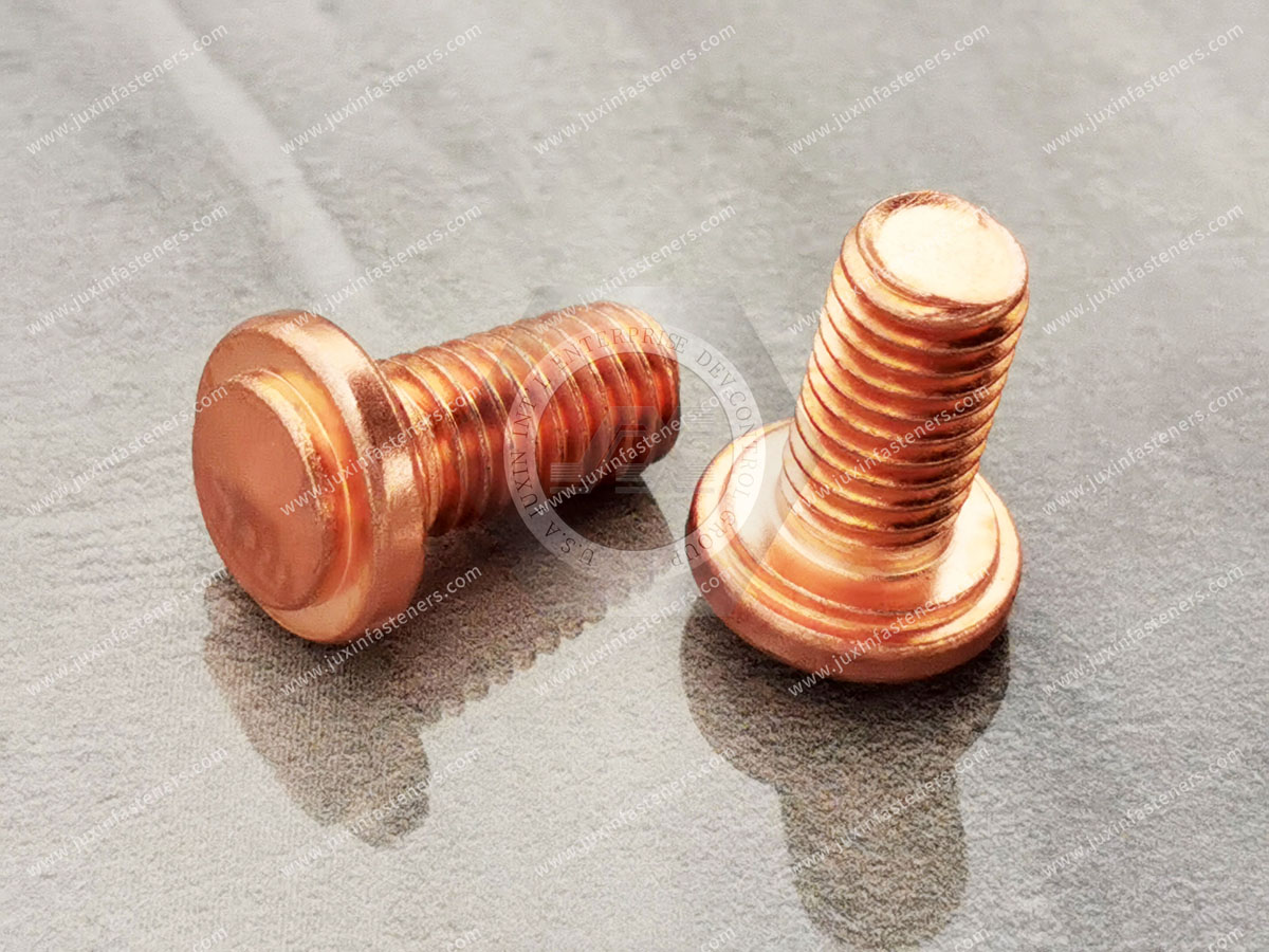
Copper plating on a weld screw should not be confused with the primary structural function of the fastener.
The welded joint obtains its mechanical performance from the interaction between the fastener, parent material, weld geometry and controlled welding process—not simply from the copper coating.
Depending on the fastener design and specified manufacturing process, a copper surface may be used to support process-related requirements such as surface condition during welding and handling.
However, copper plating should not automatically be described as providing:
Higher tensile strength
Higher weld strength
Long-term corrosion protection
Vibration locking
Sealing
Higher structural load capacity
Those properties must be determined independently according to the material, geometry, weld process, coating system, assembly design and validation requirements.
This distinction is important when engineers compare copper-plated weld screws with other weld-fastener systems.
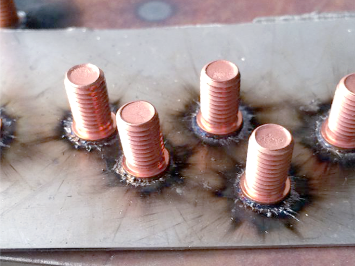
In resistance projection welding, specially designed projections localize electrical resistance and heating at selected points between the fastener and parent component.
During the welding cycle, current, force and time are controlled so that the intended weld interface forms between the components.
The result depends on several interacting variables:
fastener geometry → projection geometry → parent sheet → surface condition → electrode arrangement → welding force → current → weld time → cooling → validation
Changing one part of this system can change weld behavior.
For example, substituting a different sheet material or coating without reviewing the welding process may alter current flow, heat generation and weld formation.
For this reason, a weld screw should be treated as part of a welding system, not simply as a commodity screw with projections.
For projection-weld fasteners, the geometry of the welding projections can be one of the most important functional characteristics on the drawing.
Depending on the design, engineers may need to control:
Number of projections
Projection location
Projection height
Projection shape
Projection symmetry
Base or flange geometry
Contact area with the parent sheet
Relationship between projections and thread axis
These features influence how current and heat are concentrated during the welding cycle.
A replacement part that matches the thread and overall dimensions but uses materially different projection geometry may not behave the same way in an established welding process.
This is particularly important for second-source qualification.
The material being welded to the fastener is part of the joint specification.
Engineers should identify:
Parent-sheet material
Sheet thickness
Surface coating
Surface cleanliness
Formed geometry around the weld location
Accessibility for welding electrodes
Nearby features that may affect electrode placement
A weld screw developed for one sheet material or thickness should not automatically be assumed suitable for another.
For coated sheet, the interaction between the sheet coating and welding process also needs to be considered.
The correct question is therefore not simply:
“Can this screw be welded?”
It is:
“Can this weld screw, parent material and production welding process create the required joint consistently?”
Material selection should consider both the final mechanical requirements and weldability.
Depending on the drawing and application, weld fasteners may use suitable carbon or alloy-steel materials selected around the required manufacturing and welding characteristics.
The specification should consider:
Mechanical requirements
Weldability
Forming process
Heat-treatment condition where applicable
Thread requirements
Parent-material compatibility
Post-weld loading
Environmental exposure
Higher material strength is not automatically better for a weld-fastener application.
Changes in chemistry, hardness or heat-treatment condition may affect manufacturing and welding behavior and should therefore be evaluated as part of the complete system.
One of the practical requirements of a weld screw is that the threaded portion must remain functional after the welding operation.
Possible manufacturing and assembly risks include:
Weld spatter reaching the thread
Thread distortion
Misalignment
Heat-related effects
Damage from handling or electrodes
Contamination after welding
The production process should therefore be designed so that the mating component can be assembled correctly after welding.
Thread inspection requirements should be defined according to the applicable drawing, thread specification and customer requirements.
For OEM production, functional thread verification may be part of the agreed inspection strategy.
A weld screw can meet its individual dimensional requirements and still create an assembly problem if its final welded position is incorrect.
Depending on the application, engineers may need to consider:
Position relative to the mating hole
Angular alignment
Perpendicularity to the mounting surface
Fixture control
Electrode alignment
Movement during the welding cycle
This is especially important when the mating component has limited clearance.
The relevant functional characteristic may therefore be the position of the threaded stud after welding, not merely the dimensions of the unwelded fastener.
Weld screws are often attractive for sheet-metal assemblies because they create a permanent threaded mounting point without requiring a loose nut during final assembly.
However, thin sheet requires careful process development.
Important factors can include:
Sheet thickness
Local sheet deformation
Projection geometry
Electrode access
Heat input
Surface condition
Required joint performance
Excessive or poorly controlled welding energy can affect the parent sheet, while insufficient energy may produce inadequate weld formation.
The appropriate welding window must therefore be established for the actual fastener and assembly.
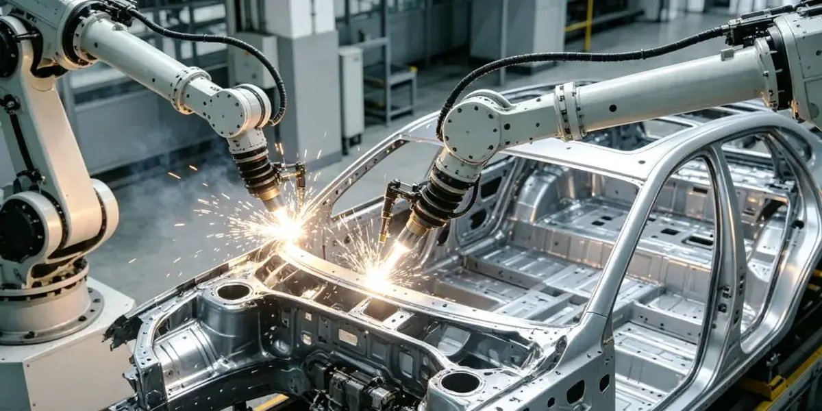
Automotive manufacturing is an important application area for projection-welded threaded fasteners because body and structural assemblies often require threaded attachment points before later assembly stages.
Depending on the vehicle design, automotive weld screws may be used for:
Body-in-white assemblies
Brackets
Equipment mounting points
Interior structures
Seat-related structures
Electrical and electronic module mounting
Underbody assemblies
Thermal-management components
EV-related enclosures and supporting structures
The specific fastener requirements depend on the location and load case.
An automotive weld screw used for a light bracket should not automatically be specified in the same way as a fastener located in a more demanding structural assembly.
OEM and Tier suppliers should define the relevant drawing, material, welding and validation requirements for each application.
EV and energy-storage manufacturing introduces large numbers of sheet-metal structures, brackets, covers, electrical components and thermal-management assemblies.
Welded threaded fasteners may be considered where a permanent male thread is needed for later assembly.
Potential applications can include:
Battery-related supporting structures
Equipment brackets
Electrical enclosures
Thermal-management assemblies
Cable or component mounting
Sheet-metal housings
The fastener should not automatically be described as suitable for battery sealing or electrical grounding merely because it is welded.
Where sealing, grounding or electrical continuity is required, those functions must be designed and validated separately at assembly level.
Copper-plated weld screws may also be used to create threaded mounting points in:
Electrical cabinets
Control equipment
Power-distribution equipment
Communications enclosures
Industrial housings
Equipment frames
In these applications, engineers may value the ability to attach the threaded fastener during sheet-metal production and then use the welded thread during later assembly.
Where electrical bonding or grounding is required, the complete electrical path and surface system should be evaluated.
The presence of copper plating on the weld screw does not by itself establish electrical bonding performance for the finished assembly.
Industrial machinery frequently combines fabricated sheet-metal components, frames, guards, cabinets and brackets.
Projection weld screws can provide permanent threaded attachment points for later installation of:
Covers
Guards
Brackets
Electrical components
Sensors
Control hardware
Auxiliary equipment
For vibration-exposed machinery, welding the screw to the structure prevents the fastener itself from being a loose component, but it does not automatically prevent the mating nut or threaded joint from rotational loosening.
The final threaded connection still requires appropriate joint design.
The terms “weld screw” and “weld stud” can overlap commercially, but the manufacturing and welding methods can differ significantly.
A projection weld screw generally uses engineered welding projections and resistance welding.
Other weld studs may be designed for processes such as stud welding, depending on the product and application.
The selection should therefore begin with:
Welding process
Fastener geometry
Parent material
Sheet thickness
Thread requirement
Required joint performance
Production equipment
Assembly sequence
The products should not be treated as interchangeable simply because both create welded threaded attachment points.
Both technologies can create permanent threaded attachment points, but they serve different assembly architectures.
A weld screw provides an externally threaded male fastening point after welding.
It may be appropriate when the later assembly uses a nut or internally threaded mating component.
A weld nut provides an internally threaded female fastening point.
It may be appropriate when the later assembly uses a bolt or screw.
The decision therefore begins with the required assembly interface rather than asking which component is “stronger.”
JUXIN FASTENERS supplies both weld screws and weld nuts, allowing engineers and sourcing teams to evaluate the appropriate configuration for the assembly.
A rivet nut and a weld screw are fundamentally different fastening technologies.
A rivet nut generally creates an internally threaded attachment point through mechanical deformation and is particularly useful where installation access is available from one side.
A weld screw creates an externally threaded feature through welding.
Important decision factors include:
Male or female thread required
Welding availability
One-sided installation requirements
Parent material
Assembly sequence
Heat input restrictions
Service requirements
Production volume
Validation requirements
Neither technology should be treated as a universal substitute for the other.
Copper plating should not automatically be selected as the final corrosion-protection strategy for a weld screw.
Its suitability depends on the coating specification, exposure conditions and subsequent manufacturing processes.
Where the finished assembly requires corrosion resistance, engineers should consider the complete corrosion-protection system, which may involve:
Parent-sheet coating
Weld-zone condition
Post-weld treatment
Paint or e-coat system
Additional surface protection
Environmental exposure
Mating components
In automotive and industrial applications, corrosion performance is frequently an assembly-level issue, particularly because welding can alter the local surface condition around the joint.
A common sourcing mistake is treating surface finish as an independent purchasing specification.
For a weld fastener, coating and welding behavior can be connected.
When reviewing a coating change, engineers should consider:
Electrical behavior during welding
Coating thickness
Surface consistency
Weld projection condition
Parent-sheet coating
Welding parameters
Post-weld corrosion strategy
Customer requirements
Changing from one finish to another may require welding-process review or revalidation.
This is why alternative-source development should not automatically substitute a visually similar coating without technical approval.
Weld quality cannot be established reliably from appearance alone.
The appropriate validation method depends on the customer specification, joint design and application.
Depending on the project, validation may include:
Dimensional inspection
Thread verification
Weld-position verification
Visual examination
Functional assembly testing
Destructive weld evaluation
Torque-related testing where specified
Push, pull or bend-related testing where specified
Metallurgical evaluation where required
Corrosion testing where specified
There is no single universal weld-strength value that applies to every copper-plated weld screw.
Acceptance criteria should be tied to the drawing, applicable specification and validated assembly.
Understanding possible failure modes helps engineers establish better specifications and sourcing controls.
Possible contributors include:
Inappropriate welding parameters
Projection variation
Surface contamination
Parent-material variation
Electrode condition
Poor component fit-up
Potential causes can include excessive heat input, unsuitable projection geometry, thin parent material or inadequate process control.
This may result from fixture movement, component positioning or electrode alignment.
Weld spatter, handling damage or deformation may interfere with later assembly.
Because projection geometry affects the welding interface, uncontrolled variation can change process behavior even when the nominal thread size remains unchanged.
The weld process may locally affect existing surface protection, making post-weld corrosion strategy important for certain applications.
These risks demonstrate why supplier qualification should focus on the fastener + weld process + parent component, not just the loose fastener.
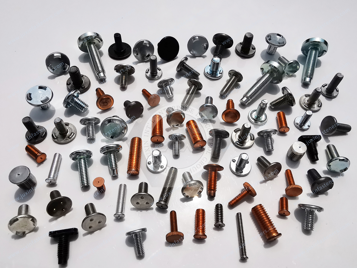
Standard products are appropriate where the required geometry and welding system match an established design.
Custom weld screws become relevant when a project requires:
Non-standard thread
Special shank length
Unique head or flange geometry
Customer-specific projection design
Restricted assembly space
Special material
Controlled surface treatment
Existing OEM replacement
Legacy-part second sourcing
Drawing-controlled dimensions
Application-specific welding requirements
JUXIN FASTENERS supports custom weld screws, projection weld fasteners, automotive fasteners and non-standard drawing-based components according to customer drawings, samples and technical specifications.
The appropriate production route depends on geometry, material, volume and application requirements.
Second-source development requires more than dimensional duplication.
The objective is to reproduce the required manufacturing and welding function.
A practical development process includes:
Identify the thread, overall geometry, projections, material and surface condition.
Determine which projection dimensions and contact surfaces directly affect weld formation.
Provide sheet material, thickness and coating information.
Where available, identify the process type and customer-controlled production requirements.
Confirm dimensional and thread requirements before assembly testing.
A geometrically similar fastener should not be approved solely from loose-part inspection.
Critical characteristics identified during development should be controlled according to the approved drawing and customer requirements.
This approach is particularly valuable for automotive supplier development, cost-reduction programs and supply-chain risk management.
For a more accurate engineering review and quotation, provide as much of the following information as available:
2D engineering drawing
3D model where relevant
Existing physical sample
Current part number
Thread size and pitch
Overall dimensions
Head or flange geometry
Projection geometry
Fastener material
Mechanical requirements
Surface finish
Parent-sheet material
Parent-sheet thickness
Parent-sheet coating
Welding process
Critical dimensions and tolerances
Functional requirements
Required validation or testing
Material documentation requirements
Inspection requirements
Sample quantity
Production quantity
Estimated annual demand
Packaging requirements
If the project is an alternative-source program, supplying the existing component together with the mating sheet-metal information can significantly improve technical review.
Not by itself.
The mechanical performance of the fastener and welded joint depends primarily on material, geometry, welding process, parent material and joint design.
It should not automatically be treated as the final corrosion-protection system.
The complete assembly environment and post-weld protection strategy must be evaluated.
No universal compatibility should be assumed.
Parent-sheet material, thickness, coating and welding parameters all influence weld behavior.
Not necessarily.
Projection geometry, material, coating, flange dimensions and welding behavior may be equally important.
They may be used in vibration-exposed assemblies where the welded joint and subsequent threaded connection are appropriately designed and validated.
Welding the fastener to the parent structure does not automatically prevent loosening elsewhere in the threaded joint.
Successful weld-fastener sourcing begins with the welding system rather than the catalog description.
A useful engineering decision path is:
application → assembly interface → parent sheet → thread requirement → fastener material → projection geometry → surface condition → welding process → validation → production control
This approach helps design engineers avoid selecting weld fasteners solely by thread size or appearance.
It also gives procurement, supplier-development and supply-chain teams a stronger technical basis for comparing suppliers, qualifying alternative sources and managing drawing-controlled OEM components.
With more than 20 years of fastener industry experience, JUXIN FASTENERS supports standard and custom
copper-plated weld screws, projection weld screws, weld nuts, weld studs, automotive fasteners and drawing-based fastening components for industrial manufacturing projects.
For new product development, existing-part replacement or second-source qualification, send your engineering drawing, physical sample and application requirements for technical review and quotation.
JUXIN FASTENERS
Industrial Fastening Solutions Since 2003
Website: www.juxinfasteners.com
Email: info@juxinfasteners.com
 MORE NEWS

Sep. 27, 2026

Sep. 27, 2026

Sep. 27, 2026
Contact Us
Tel.:
+86 020 8621 0320
+86 020 3121 6067
E-mail:
Technical Support:
Navigation
SEND INQUIREY