
Call Us
+86 136 6007 9809
Call Us
+86 136 6007 9809

Sep. 25, 2026
Standard fasteners solve millions of assembly problems efficiently.
But not every industrial assembly can be designed around a catalog bolt, screw, stud, nut, standoff, shoulder screw, or threaded insert.
Automotive systems, AI data center equipment, semiconductor machinery, electrical power equipment, medical devices, industrial automation,
thermal-management systems, and other engineered products frequently require fastening components with geometry or functional features that standard ISO,
DIN, ASME/ANSI, SAE, ASTM, or other established product ranges do not provide.
The requirement may involve:
a non-standard head profile
special shoulder diameter
controlled shoulder length
stepped shank
unusual thread length
mixed diameters
custom under-head geometry
special drive feature
restricted installation envelope
unusual material
customer-defined surface finish
integrated locating feature
special threaded stud configuration
mating-interface requirements
multiple functions integrated into one component
When this happens, engineers and procurement teams move from catalog selection to custom fasteners from engineering drawings.
Also searched as custom fasteners from existing drawings, drawing-based fastener manufacturing, made-to-drawing fasteners,
OEM custom fasteners, non-standard fasteners, custom bolts, custom screws, special threaded components, and precision machined fasteners,
these parts require a different sourcing process from standard commodity hardware.
The objective is not simply to reproduce the shape shown on a drawing.
The objective is to convert the customer's functional requirements into a repeatable, inspectable, commercially viable manufacturing process.
That requires coordination between:
Engineering drawing → application function → material → manufacturing process → tolerances → tooling → secondary operations → inspection → sample validation → production sourcing
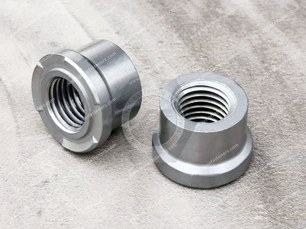
A standard catalog fastener is usually preferable when it satisfies the application.
Standardization can simplify:
sourcing
replacement
inventory
qualification
cost control
global availability
Custom hardware becomes justified when the assembly requires a function that standard hardware cannot provide without compromising the design.
Typical reasons include:
space constraints
multiple locating diameters
integrated shoulders
unusual thread engagement
special load paths
weight reduction
reduced part count
installation access
automated assembly
special corrosion requirements
electrical requirements
thermal requirements
customer-specific interfaces
The strongest custom-fastener projects therefore begin with a functional reason, not simply a preference for unique geometry.
The 2D engineering drawing remains one of the most important documents in custom fastener manufacturing.
A production drawing can define:
overall dimensions
tolerances
geometric tolerances
thread specification
material
hardness
heat treatment
surface finish
coating
plating thickness
surface roughness
critical dimensions
inspection requirements
special notes
The drawing tells the manufacturer not only what the component looks like, but which characteristics control its function.
Both can be valuable, but they serve different purposes.
The 2D print normally controls manufacturing requirements such as:
tolerances
thread class
material
heat treatment
finish
geometric tolerances
inspection criteria
special notes
A STEP or other usable 3D model can help evaluate:
complex geometry
transitions
stepped features
assembly interfaces
machining access
tooling feasibility
For complex custom fasteners, providing both a controlled 2D drawing and 3D model can reduce ambiguity.
Where the two conflict, the customer should define which document controls.
Two dimensions that appear almost identical on a drawing can have very different functional importance.
For example, a shoulder diameter may control:
bearing fit
pivot movement
concentricity
alignment
while another external diameter may only provide clearance.
Treating both with the same tolerance can increase manufacturing cost without improving assembly performance.
This is why Critical-to-Quality dimensions, or CTQs, should be identified wherever practical.
CTQ dimensions are characteristics whose variation can materially affect:
fit
function
assembly
load transfer
alignment
sealing
electrical contact
movement
service life
Potential CTQs on a custom fastener can include:
shoulder diameter
shoulder length
thread pitch
thread class
seating face
head height
concentricity
runout
locating diameter
under-head geometry
Not every dimension needs the same manufacturing precision.
A common sourcing problem occurs when very tight tolerances are applied broadly across a drawing.
Tighter tolerances can require:
additional machining
slower production
specialized tooling
additional inspection
tighter process control
higher scrap risk
The engineering question should therefore be:
Which dimensions require precision because the assembly needs it?
rather than:
How tightly can every dimension be manufactured?
This distinction can significantly improve manufacturability and cost control.
Transitions between the head, shoulder, and shank should be reviewed carefully.
Sharp geometry can create:
stress concentration
tooling difficulty
material-flow challenges
machining wear
fatigue concerns
But the correct radius depends on:
load path
mating geometry
forming process
machining process
available clearance
Therefore, arbitrary universal minimum radii should not be applied without reviewing the actual part.
Custom head designs may be required for:
restricted vertical clearance
flush installation
automated driving
tamper resistance
load distribution
aesthetic requirements
captive retention
electrical contact
Possible features include:
reduced head height
increased bearing diameter
custom recess
external drive
security drive
flange
serrations
integrated washer geometry
Head geometry can strongly influence process selection.
Custom shoulders can combine several functions in one component.
A shoulder may act as:
alignment feature
bearing surface
pivot
spacer
hard stop
locating diameter
assembly guide
Stepped fasteners may replace several separate components.
For example, one custom fastener may integrate:
Threaded section + locating shoulder + spacer section + drive head
This can reduce assembly complexity, but it also increases manufacturing and inspection requirements.
Custom hardware does not necessarily require a non-standard thread.
Where the assembly allows it, using established ISO metric or Unified inch thread systems can simplify:
tooling
gauging
mating-component sourcing
inspection
replacement
Custom geometry can therefore coexist with a standard thread.
A component might have a unique head and stepped shoulder while still using an ISO metric thread or Unified thread.
Some applications genuinely require:
special pitch
unusual thread length
left-hand thread
multiple threaded sections
customer-specific thread geometry
In these cases, the drawing should clearly define:
nominal diameter
pitch or TPI
thread form
tolerance/class
engagement requirement
inspection method
Ambiguous thread callouts are a common source of quotation and production errors.
Material selection should begin with the application rather than the manufacturing process.
Possible material families include:
carbon steel
alloy steel
stainless steel
aluminum
brass
titanium
engineering plastics such as PEEK where appropriate
Selection may depend on:
mechanical load
corrosion
temperature
weight
conductivity
magnetic requirements
chemical exposure
fatigue
mating material
regulatory requirements
The specified material must also be compatible with the proposed manufacturing process.
OEM drawings sometimes reference one regional material designation while the supply chain uses another specification system.
Equivalent-material review should compare more than a material name.
Relevant factors can include:
chemical composition
mechanical properties
heat treatment
hardness
processing route
customer approval requirements
A supplier should not automatically substitute materials based solely on a general cross-reference table.
One of the most important decisions in drawing-based fastener manufacturing is choosing the correct production route.
Common approaches include:
cold forming
CNC turning
CNC milling
thread rolling
thread cutting
grinding
secondary machining
hybrid manufacturing
The correct process depends on the complete part.
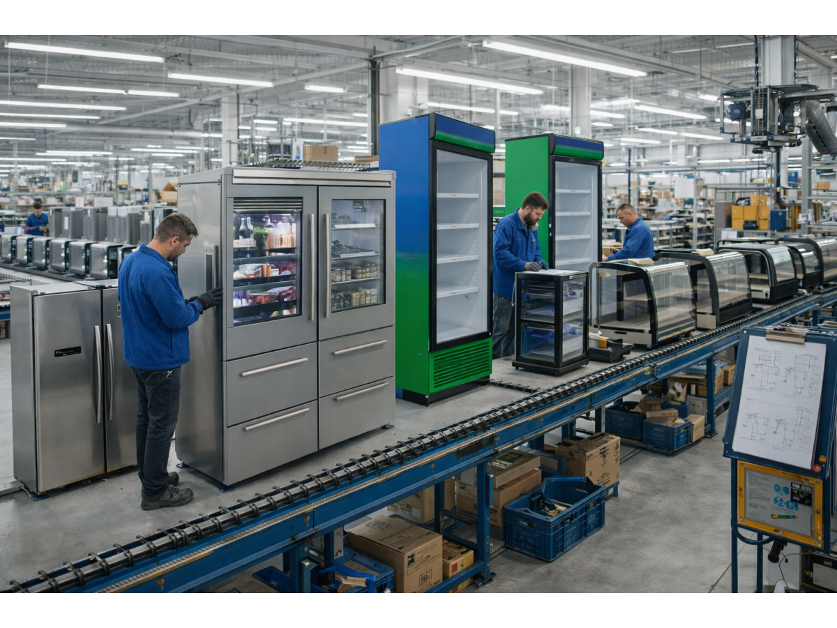
Cold forming can be highly efficient for suitable fastener geometry and production requirements.
Potential advantages include:
high material utilization
rapid production once tooling is established
repeatable geometry
favorable grain flow for appropriate features
efficient high-volume production
Potential limitations include:
tooling investment
forming-ratio limitations
material-flow constraints
geometry restrictions
tooling-development requirements
Cold forming should therefore be selected after reviewing the drawing rather than simply because the component resembles a bolt.
CNC turning provides significant geometric flexibility.
It can be suitable for parts with:
multiple stepped diameters
precise shoulders
grooves
undercuts
unusual profiles
lower initial production requirements
prototype requirements
Potential trade-offs include:
machining time
material removal
tool wear
cycle time
per-part processing cost
For some custom parts, CNC machining is the correct final production method.
For others, it is better suited to prototype or early validation.
Many commercially effective custom fasteners use more than one manufacturing process.
A hybrid route may involve:
Cold form basic blank → secondary machine critical features → roll thread → heat treat → surface finish
or:
Machine precision blank → form or roll selected features → finish → inspect
Hybrid manufacturing can combine:
forming efficiency
machined precision
standard thread tooling
controlled functional surfaces
The optimum sequence depends on geometry and production requirements.
A common oversimplification is:
Low volume = CNC
High volume = cold heading
Volume matters, but it is only one variable.
Process selection also depends on:
geometry
material
forming ratio
tolerances
surface finish
secondary features
thread design
tooling complexity
annual demand
batch size
expected program life
A high-volume component with geometry unsuitable for cold forming may still require significant machining.
A moderate-volume component may justify dedicated forming tooling if the program life and unit economics support it.
The drawing must be reviewed as a complete manufacturing problem.
| Engineering Factor | Cold Forming | CNC Machining | Hybrid Manufacturing |
|---|---|---|---|
| Production efficiency | High for suitable geometry after tooling | Depends on cycle time and complexity | Can balance forming efficiency and precision |
| Initial tooling | Custom tooling commonly required | Fixtures and tooling depend on part | Forming tooling plus secondary fixtures may be required |
| Complex stepped geometry | Geometry-dependent | High flexibility | High flexibility when features are divided between processes |
| Tight local tolerances | Depends on feature and process capability | Well suited to controlled machined features | Tight features can be machined after forming |
| Material utilization | Generally favorable | Material removed as chips | Can reduce machining compared with full bar-stock production |
| Design changes | Tooling changes may be required | Often more flexible during development | Depends on which features are formed |
| Prototype suitability | Depends on tooling strategy | Often useful for development quantities | Useful when production intent needs early validation |
| Production economics | Drawing and volume dependent | Geometry and cycle-time dependent | Program-specific |
No universal volume threshold should be used without reviewing the part.
Threads may be produced using different methods.
Thread rolling forms the thread through material displacement.
Potential advantages can include:
efficient production
good surface condition
favorable grain-flow characteristics
no thread-cutting chips
Suitability depends on:
material
thread geometry
blank diameter
hardness
production sequence
Thread cutting may be appropriate where:
geometry restricts rolling
material condition limits forming
production requirements favor machining
special thread geometry is required
The thread process should be selected according to the part rather than treated as universally interchangeable.
Custom steel fasteners may require heat treatment depending on the mechanical requirement.
The drawing should define applicable requirements such as:
strength class
hardness range
case requirement
core properties
customer specification
Heat treatment can influence:
dimensional stability
thread processing
surface treatment
hydrogen embrittlement risk for certain plated high-strength steels
Manufacturing sequence therefore matters.
Surface finish can be functional rather than cosmetic.
Possible requirements include:
corrosion resistance
friction control
electrical conductivity
appearance
chemical compatibility
wear resistance
Potential systems may include:
zinc-based coatings
zinc-nickel
zinc flake
nickel-based finishes
passivation
anodizing for suitable aluminum components
customer-defined coatings
The drawing or RFQ should define the actual performance requirement where possible.
Do not specify corrosion performance only as a generic finish name.
If corrosion testing is required, provide:
coating system
applicable ASTM, ISO, EN, or customer test method
acceptance criterion
required duration where specified
red-rust or white-corrosion requirement where applicable
This helps prevent different interpretations between engineering, procurement, supplier, and plating processor.
Inspection planning should follow the drawing and risk level.
Possible inspection methods include:
digital micrometers
calipers
height gauges
optical measurement
profile projection
thread ring gauges
thread plug gauges
surface roughness measurement
hardness testing
coating thickness measurement
CMM where appropriate
automated optical inspection for suitable production characteristics
Not every feature requires the same inspection method or frequency.
A practical inspection strategy separates characteristics into categories.
These may require:
tighter process control
dedicated gauging
higher inspection frequency
capability monitoring
These may be controlled through normal production inspection.
These should not consume unnecessary inspection resources unless the drawing or customer specification requires them.
This connects drawing design directly with production quality planning.
Custom fasteners should normally be validated before full production release according to the customer's program requirements.
Sample evaluation may include:
dimensional inspection
thread fit
assembly fit
installation
torque behavior
clamp function
alignment
corrosion testing
mechanical testing
electrical testing
environmental testing
The validation plan depends on the component and application.
An important sourcing question is whether prototype samples are produced using the same process intended for production.
For example, early samples may be CNC machined even when future production is expected to use cold forming plus secondary machining.
This can accelerate design validation.
However, engineers should understand which characteristics could change when the manufacturing process changes.
Before final production approval, production-intent samples may therefore be required.
This distinction is frequently overlooked.
A machined prototype can prove:
dimensions
fit
assembly clearance
basic function
But it may not fully represent:
formed grain flow
production tooling marks
rolled-thread characteristics
production heat-treatment distortion
final coating behavior
mass-production process capability
Prototype approval and production-process approval should therefore be treated as related but separate decisions where necessary.
AI computing infrastructure creates new mechanical and thermal packaging challenges.
Potential custom fastener applications include:
liquid-cooling equipment
server chassis
GPU trays
power shelves
rack systems
cooling distribution units
heat exchanger assemblies
Custom components may include:
stepped studs
special standoffs
shoulder screws
custom mounting bolts
threaded spacers
precision machined fasteners
The requirement may be driven by:
dense packaging
restricted clearance
serviceability
thermal architecture
vibration
equipment modularity
Liquid-cooling systems can require specialized mechanical components around:
cooling distribution units
manifolds
cold-plate mounting
pumps
heat exchangers
tubing support
Where a custom component participates directly in a pressure-containing or fluid-sealing interface, sealing geometry, material compatibility, pressure requirements, and validation must be defined by the customer.
A custom fastener supplier should not assume pressure or leak performance merely from dimensional similarity.
Automotive programs use custom fasteners where components must combine:
structural fastening
alignment
locating
vibration resistance
reduced assembly steps
restricted packaging
Potential applications include:
traction motors
battery systems
inverter housings
thermal systems
chassis assemblies
electronic control modules
Custom parts may include:
stepped studs
shoulder bolts
special flange bolts
locating screws
custom threaded pins
terminal hardware
Automotive sourcing may also require program-specific quality documentation and production approval requirements.
Battery packs and thermal-management systems create demanding combinations of:
lightweight structures
dissimilar materials
vibration
thermal cycling
corrosion exposure
sealing
A custom fastener may therefore need to coordinate with:
aluminum structures
steel brackets
busbars
cooling plates
gasketed joints
Material, coating, clamp behavior, and galvanic compatibility should be reviewed as a system.
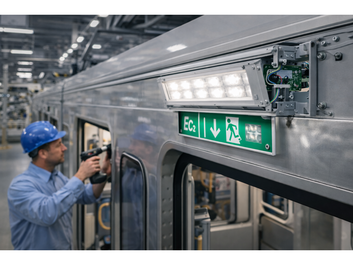
Semiconductor equipment uses precision mechanical assemblies where space, alignment, cleanliness, and repeatability can be important.
Potential custom components include:
precision shoulder screws
locating pins
threaded standoffs
stepped studs
actuator pins
custom mounting hardware
Applications may include:
wafer handling
automation modules
electronics cabinets
process equipment
inspection equipment
Tolerance and surface requirements should come from the actual equipment function rather than generic “semiconductor-grade” assumptions.
Robotic and automated equipment often requires custom mechanical hardware for:
pivots
linear mechanisms
sensors
tooling
end effectors
fixtures
guards
Potential parts include:
shoulder bolts
stepped pins
locating studs
custom screws
threaded shafts
For moving joints, engineers may need to specify:
fit
surface finish
hardness
wear
lubrication interface
concentricity
Electrical equipment can require custom fasteners for:
busbar assemblies
inverter systems
switchgear
power distribution
UPS systems
high-voltage cabinets
Custom components may combine:
mechanical retention
electrical contact
spacing
locating
anti-rotation
Where electrical conductivity or current-carrying capability is part of the function, the electrical requirement must be explicitly defined.
Energy storage equipment combines:
batteries
high-voltage distribution
power conversion
thermal management
structural enclosures
Potential custom hardware includes:
battery-module mounting studs
busbar hardware
inverter fasteners
enclosure components
custom spacers
Outdoor BESS applications may also require corrosion and environmental consideration.
Medical diagnostic and laboratory equipment can require custom hardware for:
imaging systems
analyzer mechanisms
equipment chassis
instrument positioning
serviceable modules
The sourcing process may need to address:
material documentation
cleanliness
corrosion
precision
traceability
customer-specific quality requirements
Claims regarding regulatory or medical-device compliance should be tied to the actual customer program rather than assumed from the fastener alone.
Aerospace-related custom hardware can involve strict drawing, material, process, documentation, and approval requirements.
Where aerospace specifications apply, the customer should provide the controlling drawing and required standards.
Material substitution, process changes, or functional-equivalent sourcing should not be assumed without customer authorization.
Not every legacy component has a complete drawing.
OEMs and MRO organizations may possess:
an original sample
old part number
partial drawing
assembly photographs
equipment documentation
A physical sample can be measured and evaluated to support development of a replacement component.
However, reverse evaluation cannot automatically reveal:
original material grade
heat treatment
hidden tolerances
coating specification
load requirement
original acceptance criteria
Unknown specifications should be identified and resolved with the customer rather than invented.
Sometimes an OEM does not need an exact geometric duplicate.
The actual requirement may be a functional equivalent.
This means the replacement must satisfy the required assembly functions while potentially using a different manufacturing architecture.
Qualification may compare:
envelope
thread
engagement
strength
installation
material
finish
clearance
serviceability
environmental requirements
Functional equivalence should be approved through the customer's engineering process.
Procurement teams evaluating a custom fastener supplier should look beyond the quoted unit price.
Important supplier capabilities can include:
engineering drawing review
DFM communication
cold-forming capability
CNC machining capability
thread production
secondary operations
heat-treatment coordination
surface-finishing control
dimensional inspection
material traceability
sample development
production quality control
change management
The exact capability mix required depends on the component.
A quotation should be evaluated in the context of the manufacturing process.
Two suppliers may quote the same drawing using completely different routes.
For example:
Supplier A: Full CNC machining
Supplier B: Cold forming + thread rolling + secondary machining
The quotations may have different:
tooling costs
unit costs
lead times
scalability
material utilization
process capability
change flexibility
Procurement should therefore ask:
What manufacturing route is the quotation based on?
This question can be more useful than comparing unit price alone.
Before production tooling is released, engineering and supplier teams should confirm:
critical dimensions
thread requirements
material
heat treatment
surface finish
coating
radii
undercuts
machining access
inspection requirements
annual volume
batch expectations
DFM does not mean changing the customer's design without approval.
It means identifying manufacturability issues and proposing alternatives for engineering review.
Custom manufacturing requires clear revision control.
The RFQ and purchase order should identify:
drawing number
revision
date where applicable
model revision
specification revision
This helps prevent production from using obsolete engineering data.
If the drawing changes after:
quotation
sample production
tooling
approval
the supplier should evaluate whether the change affects:
tooling
manufacturing route
material
inspection
cost
lead time
qualification
This is particularly important for multi-year OEM programs.
Where required by the customer, production documentation may include:
material certificates
lot identification
chemical composition records
mechanical-property records
heat-treatment documentation
coating documentation
The required documentation level should be defined during quotation rather than assumed.
For applicable programs, customers may request documentation relating to RoHS or REACH requirements.
The specific requirement should identify:
applicable regulation/version
material scope
finish scope
documentation expectation
Compliance claims should be based on the actual supplied material and process documentation.
Inspection should be aligned with:
drawing requirements
CTQ characteristics
process risk
customer quality plan
production volume
Possible approaches include:
first-piece inspection
in-process inspection
final inspection
sampling inspection
automated sorting for suitable characteristics
customer-specific inspection plans
Automatic sorting should not be described as a universal guarantee of zero defects.
It is one possible control method within a broader quality system.
A complete RFQ helps engineering and procurement receive a more accurate manufacturing proposal.
For custom fasteners from drawings, drawing-based fastener manufacturing, OEM custom fasteners, custom bolts, custom screws,
non-standard threaded components, or precision machined fasteners, provide as much of the following information as possible:
2D engineering drawing
drawing number and revision
3D STEP model where available
material specification
heat-treatment requirement
hardness requirement
thread specification
thread tolerance or class
critical dimensions
geometric tolerances
surface roughness where required
surface finish
coating or plating specification
coating thickness where applicable
corrosion test requirement
application description
mating-component information
mechanical load requirements where known
electrical requirements where applicable
temperature range where relevant
environmental exposure
sample quantity
prototype quantity
pilot quantity
Estimated Annual Usage (EAU)
expected production batch size
target production schedule
inspection requirements
documentation requirements
packaging requirements
If some information is not yet available, identify it as open rather than guessing.
Useful supplier-qualification questions include:
Can you review our 2D engineering drawing?
Can you work from a STEP model?
Which dimensions do you consider manufacturing-critical?
Which dimensions drive cost?
What manufacturing route do you recommend?
Is the quotation based on cold forming, machining, or hybrid production?
Which features require secondary machining?
Can the thread be rolled?
What tooling is required?
Which material condition is recommended for manufacturing?
Can the specified finish be applied to this geometry?
What prototype route will be used?
Will production use the same manufacturing route?
How will CTQ dimensions be inspected?
Which gauges or measurement methods are proposed?
What material traceability can be provided?
What coating documentation can be provided?
Can samples be supplied before production release?
How does EAU affect the manufacturing route?
What happens if the drawing revision changes?
These questions help procurement compare manufacturing proposals rather than only comparing prices.
Provide the latest controlled 2D drawing and 3D model where available.
Explain what the component does in the assembly.
Clarify which characteristics control fit, function, safety, or performance.
Review geometry, material, tolerances, thread, finish, and process feasibility.
Evaluate cold forming, machining, hybrid manufacturing, and required secondary processes.
Confirm:
tooling
sample cost
unit pricing
production volume
batch requirements
lead-time assumptions
Manufacture prototype or production-intent samples according to the agreed plan.
Verify the characteristics required by the drawing and quality plan.
The OEM validates:
fit
installation
function
mating interfaces
application performance
After technical and commercial approval, release production according to the customer's purchasing and quality process.
The strongest custom fastener sourcing programs do not end with the first quotation.
They develop through:
Drawing → DFM → process selection → quotation → sample → validation → production approval → repeat orders → revision control → long-term supply
For procurement, this creates:
controlled sourcing
clearer technical communication
repeatable quality expectations
second-source potential
lifecycle support
For engineering, it creates a direct path from design intent to manufacturable hardware.
JUXIN FASTENERS supplies standard and custom fasteners, cold-formed components, precision CNC machined parts, custom bolts,
custom screws, special studs, shoulder fasteners, threaded components, self-clinching hardware, and made-to-drawing components for industrial OEM applications.
For projects involving custom fasteners from drawings, custom fasteners from existing drawings, drawing-based fastener manufacturing,
OEM custom fasteners, custom bolts, custom screws, special threaded components, or precision machined fasteners,
our team can review customer technical documentation and evaluate an appropriate manufacturing path.
Technical review can begin from:
a 2D engineering drawing
a 3D STEP model
a customer specification
an existing fastener
a physical sample
an assembly requirement
a functional-equivalent requirement
a second-source sourcing project
Depending on geometry, material, tolerance, volume, and functional requirements, the manufacturing route may involve cold forming,
CNC machining, thread rolling, secondary machining, or a hybrid process.
For OEM programs, sample production and customer validation can be completed before production release according to the agreed project requirements.
If your engineering team already has a drawing, the most efficient first step is to send the controlled 2D print together with the material, finish, expected annual usage, and application information.
JUXIN FASTENERS can then review the drawing for manufacturing feasibility and prepare the appropriate quotation path.
For 2D/3D drawing review, DFM evaluation, custom fastener development, physical-sample evaluation, functional-equivalent sourcing,
prototype/sample requirements, or production-volume quotation, send your technical requirements to JUXIN FASTENERS.
Email: info@juxinfasteners.com
Website: www.juxinfasteners.com
 MORE NEWS

Sep. 25, 2026

Sep. 25, 2026

Sep. 25, 2026
Contact Us
Tel.:
+86 020 8621 0320
+86 020 3121 6067
E-mail:
Technical Support:
Navigation
SEND INQUIREY