
Call Us
+86 136 6007 9809
Call Us
+86 136 6007 9809

Sep. 25, 2026
Wire management inside a server chassis, electrical cabinet, telecommunications enclosure, industrial control system, or transportation electronics assembly is not simply a housekeeping issue.
Cable routing can directly affect assembly reliability, service access, airflow clearance, connector strain, abrasion risk, electrical separation, and manufacturing repeatability.
As equipment becomes more compact and wire density increases, engineers need predictable anchor points that keep cable bundles within defined routing zones.
Traditional adhesive-backed cable tie mounts can be useful where drilling or permanent panel modification is undesirable.
However, their performance depends on the adhesive system, surface preparation, substrate, temperature, humidity, contamination, vibration, applied load, and service environment.
For applications where a permanent mechanical attachment to sheet metal is preferred, self-clinching cable tie mounts provide another engineering option.
Also searched as self-clinching wire tie mounts, press-in cable tie anchors, sheet metal cable tie mounts, clinching zip tie mounts,
metal cable tie anchors, and enclosure wire management fasteners, these components create mechanically retained cable-tie attachment points directly in sheet metal panels.
For OEM design and sourcing teams, however, selecting the correct cable tie mount requires more than choosing a slot that fits a zip tie.
The complete assembly should be evaluated:
host sheet material
sheet hardness
sheet thickness
mounting-hole dimensions
fastener geometry
cable tie width and thickness
bundle diameter and mass
routing direction
expected cable movement
vibration environment
operating temperature
corrosion exposure
installation tooling
available clearance
required retention performance
The correct cable management fastener should therefore be treated as part of the enclosure and wire-harness architecture rather than as an accessory added after the chassis design is complete.
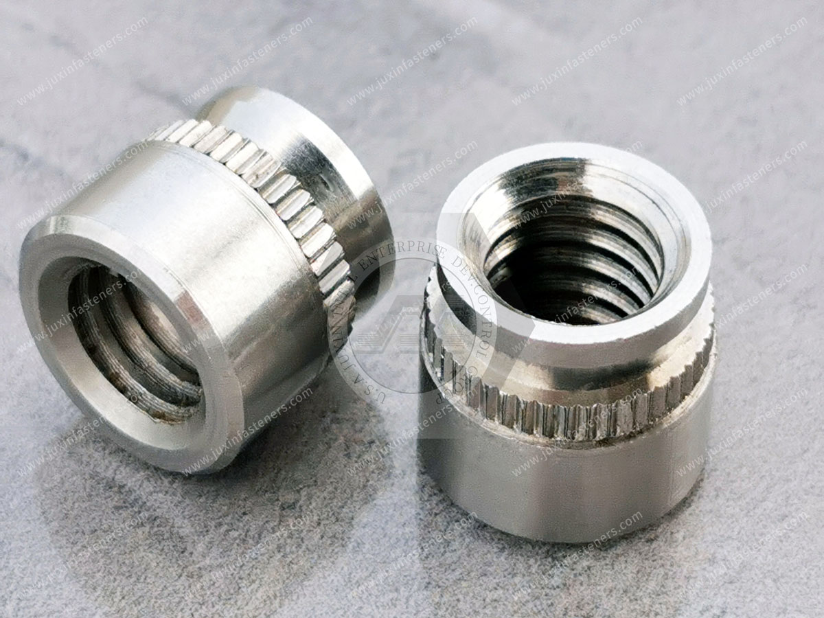
A self-clinching cable tie mount is a mechanically installed sheet-metal fastener designed to provide a permanent attachment point through which a cable tie can be routed.
Typical designs combine two functional zones.
The first is a cable tie interface, such as a slot, bridge, loop, or other opening through which a compatible nylon or metallic cable tie can pass.
The second is a self-clinching retention feature designed to mechanically engage the host sheet during controlled press installation.
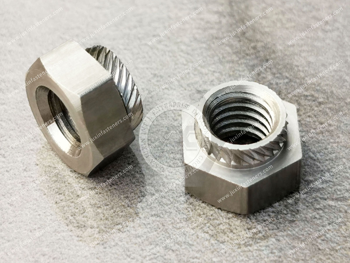
Depending on the specific design, the clinching section may use an undercut, serration, knurl, non-round geometry, or another engineered retention feature.
During installation, controlled squeezing force causes sufficiently ductile host sheet material to displace into or around the retention geometry.
The result is a mechanically retained cable anchor integrated directly into the sheet-metal panel.
This eliminates the need for a separate loose nut and bolt at the cable-management point and can reduce the need for externally projecting attachment hardware.
A cable harness inside industrial equipment is exposed to more than its own static weight.
Depending on the application, it may experience:
fan-induced vibration
equipment vibration
transportation shock
repeated service movement
connector insertion and removal
thermal expansion
cable stiffness
gravity loading
harness branching forces
maintenance handling
If an attachment point moves or releases, the cable bundle may leave its intended routing envelope.
Possible consequences include:
contact with fan blades
interference with moving mechanisms
reduced clearance around heatsinks
abrasion against sheet-metal edges
connector loading
obstruction of service access
loss of intended electrical separation
cable contact with hot surfaces
inconsistent harness position between production units
For this reason, cable management should be considered during mechanical packaging rather than left entirely to final assembly.
Adhesive-backed cable tie mounts and self-clinching cable tie mounts use fundamentally different attachment mechanisms.
An adhesive mount relies on the bond between an adhesive layer and the enclosure surface.
A self-clinching mount relies on mechanical engagement between the fastener and the host sheet.
Neither technology is universally correct for every application.
The choice depends on manufacturing sequence, service environment, panel access, structural requirements, cost, and whether permanent modification of the sheet is acceptable.
| Design Consideration | Adhesive Cable Tie Mount | Self-Clinching Cable Tie Mount |
|---|---|---|
| Attachment principle | Adhesive bond to panel surface | Mechanical clinching into prepared sheet |
| Panel hole required | Usually no | Yes |
| Press installation required | No | Typically yes |
| Surface preparation sensitivity | Can be significant | Retention depends primarily on sheet and installation conditions |
| Repositioning before final assembly | Often easier | Normally fixed after installation |
| High-temperature suitability | Depends strongly on adhesive system | Depends on fastener material, tie material, and assembly conditions |
| Vibration performance | Depends on adhesive, substrate, load, and environment | Depends on fastener geometry, sheet, installation, and applied load |
| Reverse-side condition | No mounting hole penetration in typical adhesive designs | Depends on clinch design and installed geometry |
| Production repeatability | Depends on surface preparation and bonding process | Can be controlled through hole preparation and press installation |
| Best use case | Applications suited to bonded attachment | Applications requiring permanent mechanical sheet-metal anchoring |
The engineering question should therefore not be:
“Are mechanical mounts always better than adhesive mounts?”
A more useful question is:
“Which attachment mechanism remains compatible with the actual panel, environment, manufacturing process, and required cable-routing function?”
Pressure-sensitive adhesive systems can perform successfully when they are correctly matched to the substrate and environment.
However, bond performance may be affected by variables such as:
surface contamination
oils and manufacturing residues
surface energy
paint or powder coating
application pressure
adhesive cure or dwell time
temperature
humidity
chemical exposure
vibration
sustained peel loading
cable bundle weight
thermal cycling
This becomes particularly relevant in high-density electronics and industrial equipment where internal operating conditions can differ substantially from room-temperature assembly conditions.
An adhesive mount that initially feels secure during assembly should not automatically be assumed to retain the same performance under the equipment's full service environment.
If adhesive attachment is used in a critical harness location, the adhesive system should be qualified for the actual substrate and operating conditions.
Where a mechanical attachment is preferred, a self-clinching cable tie mount removes the adhesive bond from the primary panel-retention mechanism.
This distinction is important.
A metal self-clinching cable tie mount does not depend on an adhesive layer for its attachment to the sheet.
However, the complete cable retention system may still contain temperature-sensitive components.
For example, if a nylon cable tie is routed through a stainless steel or plated steel clinching mount, the allowable service temperature of the assembly can still be limited by:
cable tie polymer
cable insulation
connector materials
nearby components
coatings
environmental requirements
Therefore, an all-metal anchor should not be described as making the complete cable-management system universally immune to heat.
The anchor material and cable tie material must be evaluated separately.
For elevated-temperature applications, engineers may consider suitable high-temperature polymer ties or metallic cable ties where appropriate to the application.
The mechanical principle is similar to other self-clinching sheet-metal fasteners.
A prepared mounting hole receives the fastener's clinching section.
Controlled squeezing force is then applied using suitable tooling.
During installation, host sheet material is displaced into the fastener's retention features.
After the installation force is removed, this mechanically engaged material helps resist axial movement.
Depending on fastener geometry, additional features may help resist rotation or movement under cable loading.
Actual retention performance depends on the complete fastener-panel system, including:
fastener design
fastener material and hardness
sheet material
sheet hardness
sheet thickness
mounting-hole dimensions
edge distance
installation tooling
press setup
applied cable load
This is why catalog retention values should not automatically be transferred to a different sheet material or installation condition.
The cable tie slot is often treated as a minor dimension.
It should not be.
The slot or bridge is the interface between the metal anchor and the cable tie, and it affects assembly efficiency, cable-tie selection, routing direction, and local stress.
Engineers should consider:
maximum cable tie width
cable tie thickness
metallic versus polymer tie
insertion direction
slot edge geometry
required routing angle
bundle diameter
available installation access
A slot that is too narrow prevents assembly.
A slot with inadequate clearance can make production installation difficult.
A slot that is excessively large may consume unnecessary chassis space or alter the desired low-profile design.
For custom applications, cable tie dimensions should therefore be included in the fastener RFQ rather than specifying only the sheet-metal mounting dimensions.
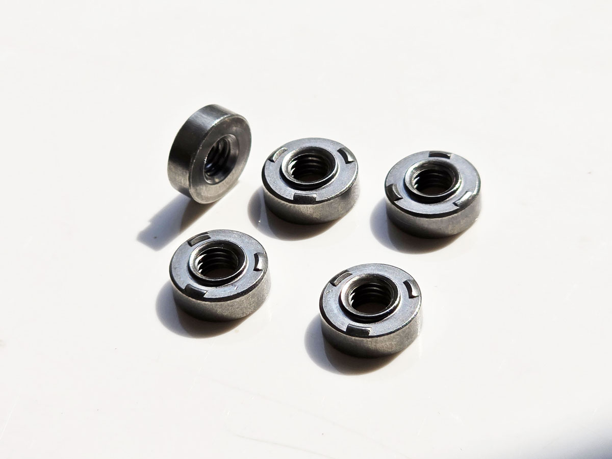
A useful design rule is to define the harness path before fixing the cable tie mount orientation.
The cable tie must pass through the mount and around the bundle without forcing an undesirable twist or bend.
This means the CAD design should consider:
intended cable path
bundle diameter
cable tie entry direction
tool or operator access
tightening direction
cut-tail access
nearby components
required bend radius
Only then should the mounting-hole position and slot orientation be finalized.
This can prevent a common production problem: a mechanically correct anchor that is awkward for the assembly operator to use.
Self-clinching retention depends on controlled deformation of the host sheet.
The host material must therefore be compatible with the selected fastener's clinching mechanism.
Potential host materials can include:
cold-rolled steel
aluminum alloys
suitable stainless steel sheet
other ductile sheet materials approved for the fastener design
Material designation alone is not enough.
Hardness, temper, work hardening, coating, sheet thickness, and forming history can affect installation behavior.
The fastener supplier's specified application limits should be reviewed against the actual production sheet.
When the application is critical or the production material differs from previously validated conditions, installation trials using representative sheet are advisable.
Mounting-hole geometry directly affects clinching performance.
The hole should be produced to the dimensional requirements of the selected fastener.
Relevant variables may include:
hole diameter
hole tolerance
hole roundness
burr condition
panel flatness
distance from panel edge
distance from bends
nearby formed features
Unapproved chamfering, countersinking, or excessive deburring can remove material that may be needed for the clinching mechanism.
Conversely, excessive burrs can interfere with seating.
The correct hole condition depends on the specific fastener design and should follow the applicable drawing or supplier installation specification rather than a universal shop rule.
Self-clinching cable tie mounts are normally installed by controlled pressing using suitable punch and anvil tooling.
Installation should produce the intended mechanical engagement without damaging the cable tie slot, distorting the panel, or creating unwanted projection on the opposite surface.
Important process variables include:
press force
press stroke
punch geometry
anvil geometry
tooling alignment
fastener orientation
panel support
installation depth
sheet thickness
sheet hardness
More installation force does not automatically produce a better joint.
Insufficient force can leave the mount incompletely seated.
Excessive force may distort the sheet or fastener.
For production applications, the installation process should be established through controlled trials and monitored according to the OEM's quality requirements.
One reason engineers choose self-clinching cable management hardware is the possibility of maintaining a relatively clean opposite panel surface compared with through-bolted cable anchors.
However, the installed reverse-side condition depends on the specific fastener geometry and panel.
It should not automatically be described as perfectly flush.
Designers should check:
permitted projection
neighboring equipment clearance
enclosure-to-enclosure spacing
cosmetic surface requirements
slide or guide paths
gasket surfaces
adjacent covers
If the reverse side has a strict no-protrusion requirement, that condition should be explicitly included in the drawing and validated on installed samples.
Cable routing can influence airflow, particularly in high-density forced-air-cooled equipment.
The important mechanism is not that a small cable tie mount automatically produces a measurable cooling improvement.
Rather, predictable cable retention can help keep harnesses within their intended routing zones and away from airflow paths.
In server and power-electronics equipment, engineers may define regions that should remain clear for:
fan inlet flow
fan discharge flow
heatsink channels
GPU or accelerator cooling paths
power supply airflow
air baffles
heat exchanger interfaces
Mechanical cable anchors can help maintain the designed harness position within these constraints.
The actual thermal effect depends on the complete chassis architecture and should be evaluated through the OEM's normal thermal analysis, CFD, prototype testing, or system validation where required.
A useful way to improve wire-management design is to stop treating the harness as a line in CAD.
A real harness occupies a three-dimensional volume.
Its position can change because of:
cable stiffness
bundle diameter
connector orientation
gravity
vibration
manufacturing tolerance
technician handling
service loops
Instead of defining only the nominal harness centerline, engineers can define a cable routing envelope.
The enclosure design can then position mechanical anchor points so the entire expected harness envelope remains clear of:
fans
heatsinks
sharp edges
moving mechanisms
high-temperature surfaces
access panels
sensitive signal components
This transforms cable management from an assembly afterthought into a controlled mechanical packaging function.
There is no single cable tie mount spacing that is correct for every wire harness.
Required spacing depends on factors including:
bundle mass
cable stiffness
routing orientation
vibration
equipment motion
service loops
connector loads
allowable sag
environmental conditions
cable tie properties
mount retention capacity
A heavy vertical power harness in transportation equipment can require a different retention strategy from a lightweight sensor harness inside stationary instrumentation.
Engineers should establish spacing based on the actual harness and application requirements rather than applying an arbitrary universal interval.
High-density AI servers can contain substantial power, control, sensor, fan, and communication cabling inside a limited chassis envelope.
Potential applications for self-clinching cable tie mounts include:
GPU server chassis
accelerator platforms
rack-mounted power shelves
server side walls
fan partitions
cable guide panels
storage enclosures
network switches
control and sensor harness zones
In these assemblies, predictable cable routing can help keep harnesses away from:
high-speed fan assemblies
airflow channels
heatsinks
removable compute modules
slide mechanisms
service access paths
For server OEMs, the value of a mechanical cable anchor is therefore not merely that it holds a cable tie.
It can establish a repeatable cable-routing point in every manufactured chassis.
This improves consistency between the mechanical design intent and production assembly.
Rack-mounted power equipment and power distribution units can contain multiple conductor groups, sensing wires, control harnesses, and communication cables.
Cable anchor locations may be designed to support:
power conductor routing
control wiring
sensing harnesses
internal communication cables
service loops
cable separation
Where electrical separation or clearance requirements apply, the cable mount itself does not create compliance.
Instead, it can help maintain the routing geometry established by the electrical and mechanical design.
Applicable equipment standards, wiring requirements, creepage and clearance rules, and customer specifications must still be evaluated for the complete assembly.
Industrial electrical cabinets contain combinations of:
power cables
signal wiring
communication cables
grounding conductors
sensor harnesses
control wiring
Applications can include:
variable frequency drive cabinets
inverter enclosures
power conversion systems
industrial control panels
UPS equipment
electrical distribution cabinets
energy storage control systems
Self-clinching cable tie mounts can provide permanent routing points in sheet-metal walls, dividers, brackets, and internal mounting structures.
They may be particularly useful where the enclosure manufacturer wants cable management hardware installed during sheet-metal fabrication before final electrical assembly.

Telecommunications and network equipment often combines dense electronics with extensive internal cable routing.
Potential applications include:
optical networking equipment
telecom cabinets
network switches
radio equipment
base station enclosures
communication power systems
modular network chassis
Mechanical cable anchors can help maintain predictable harness routing while equipment is transported, installed, serviced, or exposed to continuous fan vibration.
For outdoor telecommunications equipment, material and surface-finish selection should also consider the enclosure's environmental and corrosion requirements.
Automation equipment frequently contains distributed power, control, sensor, communication, and actuator wiring.
Potential applications include:
robot control cabinets
packaging machinery
automated assembly systems
machine-tool enclosures
material-handling systems
process equipment
control-panel assemblies
Cable routes in this equipment may be located near moving mechanisms or serviceable modules.
Mechanical anchor points can help keep fixed harness sections inside defined zones.
They should not, however, be used to restrict cable sections that are intentionally designed to flex or move.
Dynamic cable systems require appropriate cable carriers, bend-radius control, strain relief, and motion-specific engineering.
Rail and transportation equipment can expose wiring systems to vibration, shock, temperature variation, and extended service periods.
Potential applications include:
locomotive electrical cabinets
passenger rail control equipment
onboard communication systems
vehicle electronic enclosures
battery compartment panels
auxiliary power systems
transportation control cabinets
In these environments, cable anchor qualification should consider the actual vehicle or equipment requirements.
The fact that a mount is mechanically clinched does not by itself establish compliance with vibration, shock, fire, smoke, electrical, or transportation-specific requirements.
Those requirements should be validated at the assembly and system level according to applicable standards and customer specifications.
Medical diagnostic and laboratory equipment can contain dense internal electronics and harnesses while also requiring frequent service access.
Potential applications include:
imaging equipment
laboratory analyzers
diagnostic carts
medical displays
control cabinets
laboratory automation systems
Mechanical cable tie anchors can provide repeatable harness positions inside sheet-metal structures.
However, material selection and fastener geometry should be evaluated against the actual equipment's cleanliness, corrosion, service, electrical, and regulatory requirements.
A cable tie mount alone should not be interpreted as establishing medical-device compliance.
Semiconductor equipment combines precision motion, power systems, control electronics, sensors, pneumatics, vacuum-related equipment, and complex wiring architectures.
Potential mounting locations include:
electrical cabinets
control modules
instrument housings
sheet-metal partitions
equipment side panels
service modules
In precision equipment, controlling the harness envelope can be particularly useful where cables must remain clear of motion systems,
service paths, optical components, or thermal management hardware.
Commercial HVAC systems can contain controls, sensors, drives, communication wiring, and power electronics inside sheet-metal enclosures.
Applications may include:
control cabinets
inverter compartments
fan-control assemblies
building automation equipment
heat-pump electronics
air-handling equipment controls
Mechanical cable tie mounts can be evaluated where permanent sheet-metal cable routing is preferable to adhesive attachment.
Environmental exposure, condensation, temperature, corrosion, and service access should be considered when selecting fastener material and finish.
Self-clinching cable tie mounts may be manufactured from materials such as carbon steel or stainless steel depending on design and application.
Material selection should consider:
host sheet compatibility
fastener hardness
corrosion environment
installation behavior
temperature
electrical considerations
customer specifications
downstream finishing processes
Carbon steel designs may use zinc-based or other specified surface treatments.
Stainless steel may be considered where corrosion resistance or material compatibility makes it appropriate.
The exact material and finish should be defined according to the application rather than assumed from the product category.
Surface finish can influence corrosion resistance, dimensional interfaces, appearance, and compatibility with the surrounding assembly.
Depending on the project, sourcing discussions may include:
zinc-based finishes
zinc-nickel systems
passivated stainless steel
other customer-specified finishes
Rather than requesting a generic “corrosion-resistant coating,” OEM buyers should provide the required environmental condition, test requirement,
or applicable customer specification where available.
Any required corrosion test duration or acceptance criterion should be tied to the governing specification rather than generalized across industries.
The anchor and the cable tie should be specified as separate components within the retention system.
Nylon cable ties are widely used because they are lightweight, economical, and easy to install.
Metallic cable ties may be considered for applications involving different temperature, mechanical, environmental, or material requirements.
Selection depends on factors including:
operating temperature
required loop strength
chemical environment
fire requirements
vibration
bundle diameter
installation tooling
service requirements
The cable tie slot in the clinching mount must be compatible with the selected tie dimensions and material.
A mount qualified with one cable tie should not automatically be assumed to provide identical system performance with a different tie.
This is an important design distinction.
A cable tie mount can control harness position.
That does not automatically mean it provides the required connector strain relief.
If external pulling force can be transferred through the harness into a connector, terminal, gland, or PCB interface, dedicated strain-relief design may still be required.
Engineers should distinguish between:
Routing retention — keeping the harness in the intended location.
Strain relief — preventing mechanical load from reaching a sensitive termination.
Some assemblies may use the same mounting architecture to support both functions, but this should be intentionally designed and validated rather than assumed.
Push-out testing can help evaluate how strongly the installed mount is retained against axial displacement from the panel.
Results depend on:
fastener geometry
sheet material
sheet hardness
sheet thickness
mounting hole
installation force
tooling
edge distance
For OEM qualification, test samples should reproduce the intended production conditions as closely as practical.
A value generated in one panel configuration should not automatically be treated as representative of another.
Cable tie mounts can experience loads in directions different from conventional threaded clinch nuts.
Depending on cable routing, the tie may pull:
parallel to the panel
perpendicular to the panel
at an angle
cyclically because of vibration
This means push-out testing alone may not fully represent the application.
Where harness loads are significant, engineering teams should consider the actual direction of force applied through the cable tie and mount.
Application-specific pull testing can provide more meaningful information than relying only on a generic axial retention value.
The mechanical system contains several interfaces:
Sheet → Clinching Mount → Cable Tie → Wire Bundle
Failure can occur at any of them.
The clinching mount may remain perfectly attached while the cable tie fails.
The cable tie may remain intact while excessive harness movement damages insulation.
The complete assembly should therefore be evaluated rather than qualifying only the metal fastener.
For critical applications, validation may include:
mount push-out testing
directional pull testing
cable tie loop testing
vibration testing
thermal exposure
environmental conditioning
harness abrasion inspection
service-cycle evaluation
The required test program depends on the application.
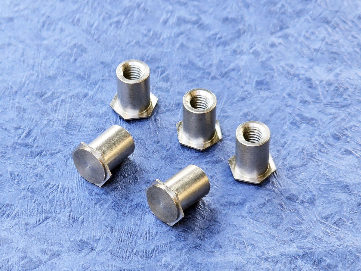
Procurement teams may need an alternative source because of capacity, lead time, regional supply strategy, supplier consolidation, cost, business continuity, or an obsolete component.
For self-clinching cable tie mounts, matching only the overall appearance is insufficient.
A functional-equivalent review should compare:
mounting-hole diameter
compatible sheet thickness
clinching geometry
cable tie slot width
cable tie slot height
head dimensions
installed profile
fastener material
hardness
surface finish
corrosion requirement
push-out performance
directional pull performance where applicable
installation tooling requirements
packaging and quality documentation
A part can fit the same cable tie but require a different mounting hole.
Another part can fit the same mounting hole but provide a different installed height.
A third can appear dimensionally similar but behave differently in the customer's actual sheet material.
Functional equivalence should therefore be established through geometry, material, installation, and performance review.
A structured qualification process can reduce sourcing risk.
Provide the existing component drawing, reference part, specification, or sample.
This gives the supplier a basis for dimensional and functional review.
Provide:
material
thickness
hardness where specified
mounting-hole dimensions
coating condition
nearby bends
edge distance
required opposite-side profile
Provide:
material
width
thickness
approximate bundle size
required routing orientation
This is essential because the cable tie is part of the fastener interface.
Compare the proposed fastener against the current assembly requirements rather than simply comparing catalog names.
Check:
seating
panel distortion
mount orientation
slot accessibility
reverse-side condition
cable tie installation
harness routing
Depending on the program, testing may include:
push-out
directional pull
vibration
corrosion
thermal exposure
cable tie retention
production installation trials
Only after the geometry, installation, material, finish, and performance requirements are confirmed should the alternative proceed into production sourcing.
A generic sheet coupon is useful for initial testing.
However, it may not reproduce the actual production condition.
Production panels can differ in:
hardness
thickness tolerance
coating
forming history
work hardening
hole quality
nearby bends
local panel stiffness
These factors can influence clinching behavior.
For important applications, final qualification should therefore use representative production material and installation conditions.
A cable management component must be easy to manufacture consistently.
Production engineers should consider:
how the mount is fed or handled
how slot orientation is controlled
whether installation tooling can access the location
how the panel is supported
whether the press can control installation depth
whether the mount damages surrounding coating
whether operators can easily pass the cable tie through the slot
whether the tie can be tensioned and trimmed without interference
whether installation can be visually or dimensionally inspected
A good fastener design reduces both field risk and assembly complexity.
Standard hardware may not satisfy every enclosure architecture.
A custom or drawing-based cable tie mount may be considered when the application requires:
special tie-slot dimensions
non-standard slot orientation
unusual panel thickness
restricted installed height
special mounting-hole geometry
non-standard material
special surface finish
specific clearance requirements
application-specific pull performance
unique enclosure packaging constraints
Custom development is generally more practical when the technical requirement and expected volume justify tooling and qualification.
Providing a 2D drawing or 3D model allows the supplier to evaluate manufacturability more effectively than describing the requirement only by email.
For an OEM sourcing program, useful questions include:
What sheet materials are compatible with this mount?
What sheet-thickness range applies?
What mounting-hole dimensions are required?
What cable tie width and thickness can the slot accept?
What installation tooling is recommended?
What materials and finishes are available?
Can the supplier review our existing drawing?
Can samples be supplied for production-sheet testing?
Can a functional equivalent be evaluated against an existing part?
Can a custom configuration be manufactured from our drawing?
What inspection and material documentation can be provided for the quoted program?
What packaging and lot-identification options are available?
What EAU information is required for production pricing?
These questions help procurement compare technically relevant proposals rather than comparing unit prices for parts that may not be functionally equivalent.
A complete RFQ helps engineering and sourcing teams obtain a technically meaningful quotation with fewer clarification cycles.
For self-clinching cable tie mounts, press-in cable tie anchors, or other sheet metal cable management fasteners, provide as much of the following information as possible:
2D drawing
3D STEP model where available
existing part number or reference component
physical sample where cross-referencing is required
host sheet material
host sheet thickness
sheet hardness where controlled
mounting-hole diameter and tolerance
required installed profile
cable tie material
cable tie width
cable tie thickness
bundle size
expected bundle mass where relevant
fastener material
surface finish
corrosion requirement
operating temperature range
vibration or shock requirements where applicable
mechanical retention requirements
sample quantity
prototype quantity
Estimated Annual Usage (EAU)
packaging requirements
documentation requirements
production schedule
The more accurately the supplier understands the panel, cable tie, environment, and load condition, the more meaningful the proposed fastener solution will be.
The most productive sourcing process starts with the assembly problem.
For an electrical packaging engineer, the problem may be a cable bundle migrating toward a fan.
For a mechanical engineer, it may be insufficient space for conventional cable mounting hardware.
For a manufacturing engineer, it may be inconsistent adhesive preparation or cable tie orientation.
For procurement, it may be a second-source requirement for an existing cable management component.
For supplier development, it may be a need to qualify a functionally equivalent fastener against an existing drawing.
These paths can be translated into a common sourcing workflow:
Harness routing requirement → cable envelope definition → panel and tie specification → fastener selection
→ drawing review → sample installation → application testing → production qualification → volume sourcing
This creates a much stronger technical and commercial foundation than sourcing a cable tie mount solely by appearance.
JUXIN FASTENERS supplies engineered self-clinching hardware, cable tie mounts, press-in wire anchors, threaded inserts,
panel fasteners, and custom fastening components for OEM and industrial applications.
For projects involving self-clinching cable tie mounts, sheet metal cable tie anchors, press-in wire management hardware,
or custom cable-management fasteners, our team can review customer drawings and application requirements to evaluate the appropriate manufacturing and sourcing path.
Technical review can begin from:
a customer 2D drawing
a 3D model
an existing fastener specification
a physical sample
host-panel information
cable tie dimensions
a functional-equivalent requirement
a new OEM cable-management application
Where retention performance is important, sample installation and testing using representative production sheet, the intended cable tie,
and application-relevant loading conditions are recommended before final production approval.
For drawing review, sample evaluation, functional-equivalent sourcing, custom cable tie mount development, or volume quotation, send your technical requirements to JUXIN FASTENERS.
Email: info@juxinfasteners.com
Website: www.juxinfasteners.com
 MORE NEWS
Sep. 24, 2026
Contact Us
Tel.:
+86 020 8621 0320
+86 020 3121 6067
E-mail:
Technical Support:
Navigation
SEND INQUIREY