
Call Us
+86 136 6007 9809
Call Us
+86 136 6007 9809

Sep. 12, 2026
For OEMs, Tier-1 suppliers, and industrial manufacturers, the quality of a custom metal component is determined by more than its appearance or unit price.
A drawing-based fastener, CNC-machined component, precision washer, shaft, pin, bracket, rivet, or other application-specific metal part may contain multiple requirements that directly affect assembly,
interface compatibility, material selection, surface condition, and production consistency.
A thread that does not match the specified requirement, a material grade that has not been properly verified, an incorrect surface treatment,
or a critical dimension that drifts outside the approved specification can create receiving problems, assembly interruptions, rework, supplier corrective actions, or broader production risks.
This is why custom metal component quality should be evaluated as a complete verification process rather than as a final visual inspection.
For OEM procurement and quality teams, the practical question is not simply:
“Does the supplier inspect the parts?”
The more useful question is:
“Can the supplier connect the engineering requirement to the manufacturing process, inspection method, acceptance criterion, documentation, and production lot?”
JUXIN FASTENERS is an OEM-oriented supplier of customer-specific, non-standard, and application-specific fastening and precision metal components.
Depending on the component and project requirements, manufacturing routes may include CNC machining,
cold heading or forging, multi-stage forming, stamping, and other suitable processes. Customer requirements may be provided through 2D engineering drawings, 3D CAD files,
samples, specifications, inspection requirements, or application information.
Quality verification can include dimensional measurement, thread inspection, material verification, hardness or mechanical testing where specified,
surface treatment verification, functional inspection, and batch traceability according to the requirements agreed for the project.
This guide explains how engineering, quality, procurement, and supply chain teams can structure quality and inspection requirements for custom metal components before RFQ, supplier approval,
sample approval, and production.
Custom metal component quality and inspection requirements are the technical criteria used to confirm that a drawing-based or application-specific component conforms to the customer's approved specification.
These requirements can cover:
Critical-to-function dimensions
General dimensional requirements
Geometric tolerances and GD&T where specified
Thread dimensions and characteristics
Hole diameter and position
Material grade and material condition
Heat-treatment requirements where applicable
Surface finish
Surface treatment or coating
Functional characteristics
Assembly interfaces
Visual requirements
Packaging and identification
Lot traceability
Inspection frequency
Required inspection reports
Material documentation
Certificates of Conformance where specified
Sample or first-article approval requirements
Drawing revision control
The important distinction is between the requirement itself and the method used to verify it.
For example:
Drawing Requirement → Critical Characteristic → Manufacturing Process → Inspection Method → Acceptance Criterion → Inspection Record
This connection is one of the most useful ways for an OEM quality or procurement team to evaluate a custom component supplier.
A supplier may have inspection equipment, but the more important question is whether the inspection plan is aligned with the actual engineering requirements of the part.
Custom metal components create a different quality-management challenge from simple commodity purchasing.
A standard catalog fastener may have an established dimensional specification and conventional inspection approach.
A customer-specific component, however, may combine a unique geometry, special material, unusual thread interface, surface treatment, and application-specific functional requirement.
Several risks therefore need to be addressed during sourcing.
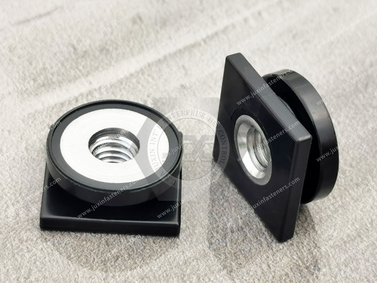
Dimensional variation can become significant when a component interfaces with another precision-machined or formed part.
For example, variation in:
thread dimensions,
hole diameter,
shaft diameter,
shoulder location,
overall length,
mating diameter,
mounting interface,
or critical positional dimensions
may affect assembly.
The correct response is not to assume that every dimension requires the same inspection intensity.
Instead, engineering and quality teams should identify which characteristics are critical to function or assembly and define the appropriate inspection method for those characteristics.
Material substitution can create serious sourcing risk when the material specified on the drawing is not adequately controlled.
The requirement may involve:
carbon steel,
alloy steel,
stainless steel,
aluminum,
brass,
titanium,
or another customer-specified material.
The exact grade, condition, and treatment should come from the approved engineering specification.
Material verification may involve supplier documentation, material certificates, identification records, or testing where required by the project.
The key procurement principle is simple:
Do not treat “stainless steel,” “aluminum,” or “steel” as a complete material specification when the drawing requires a specific grade or condition.
Quality documentation can become a supply-chain issue when requirements are not defined before production.
Depending on the project, an OEM may require:
dimensional inspection reports,
material documentation,
Certificates of Conformance,
inspection records,
lot identification,
surface-treatment documentation,
functional test records,
sample approval records,
or other customer-specific quality documents.
These requirements should be agreed before volume production rather than introduced after shipment.
A technically correct part can still become a quality problem if it is manufactured or inspected against the wrong drawing revision.
For customer-specific components, procurement and supplier quality teams should establish clear control of:
drawing revision,
CAD revision,
specification revision,
material requirements,
inspection requirements,
approved samples,
and engineering changes.
This becomes especially important when the same component is supplied over an extended production period.
A practical quality protocol should connect the customer's engineering requirements to measurable verification activities.
Not every drawing dimension has the same functional importance.
Critical characteristics may include:
thread dimensions,
mating diameters,
mounting-hole dimensions,
shaft dimensions,
shoulder positions,
interface locations,
critical lengths,
clearance-related dimensions,
or other customer-defined characteristics.
The inspection plan should identify these characteristics and define how they will be measured.
Material control begins with the approved specification.
Depending on the project, verification may include:
material grade,
material condition,
supplier documentation,
lot identification,
heat or batch information,
hardness,
chemical composition,
or other agreed testing.
Not every project requires every test. The inspection method should correspond to the customer's specification and risk level.
Surface treatment can be an important part of custom metal component quality.
Depending on the application, the specification may identify:
zinc-based plating,
Zinc-Nickel Alloy,
passivation,
anodizing,
hard anodizing,
electroless nickel,
functional coatings,
lubricating coatings,
or other customer-specified treatments.
Verification requirements may include coating identity, appearance, thickness, corrosion-related testing, or other characteristics where specified.
The important point is that surface treatment should not be treated as a generic “finish” field.
The correct requirement depends on:
Base Material + Surface Treatment + Mating Material + Assembly Method + Environmental Exposure + Customer Specification
For example, a surface treatment used on an automotive chassis fastener may have different requirements from one used on an interior component.
Traceability requirements vary between customers and applications.
Where required, lot identification may connect:
Raw Material → Production Lot → Inspection Record → Finished Components → Shipment
This can make investigation and corrective-action activities more manageable if a quality issue is identified later.
Documentation should be defined according to the customer's quality agreement.
Possible documents include:
Dimensional inspection reports
Material documentation
Certificates of Conformance
Hardness or mechanical test reports where applicable
Surface-treatment records
Functional inspection records
Sample approval documentation
Lot identification records
The correct approach is customer-defined documentation, rather than assuming that every project requires the same quality package.
For a broader framework on evaluating custom-component suppliers, see Custom Automotive Component Sourcing & Supplier Evaluation Protocol.
Engineering and procurement teams often evaluate quality from different angles.
A successful OEM sourcing program needs both perspectives.
Engineers are generally concerned with whether the component conforms to the technical requirements of the joint or assembly.
Typical concerns include:
dimensional accuracy,
GD&T,
mating interfaces,
thread engagement,
material compatibility,
surface condition,
functional dimensions,
assembly method,
application environment,
and validation requirements.
Engineers may also need to understand which characteristics are actually critical to the function of the component.
For example, a custom shaft may contain several dimensions, but the diameter and shoulder location that interface with another mechanism may have greater functional importance than a non-critical external dimension.
Procurement and supply chain teams need to translate those technical requirements into a repeatable supply process.
Typical concerns include:
supplier capability,
quality consistency,
inspection documentation,
material traceability,
production capacity,
lead time,
packaging,
corrective-action responsiveness,
change management,
and long-term supply continuity.
The two perspectives therefore meet at one important point:
The supplier must understand what matters technically and control it consistently commercially.
International standards provide recognized technical frameworks for dimensions, threads, materials, testing, and engineering documentation.
However, a standard should not be inserted into a specification simply because it is internationally recognized.
The correct standard depends on the actual component and customer drawing.
ISO standards may define requirements related to:
metric threads,
dimensional tolerances,
geometrical tolerancing,
fastener dimensions,
mechanical properties,
and other engineering specifications.
DIN standards are widely referenced in European engineering and can apply to standardized fasteners, washers, pins, spacers, and other mechanical components.
ASME and ANSI-related specifications are commonly encountered in North American engineering applications, including unified thread systems and dimensional requirements.
EN standards may be relevant to European automotive and industrial applications where the customer specification references a European standard.
SAE specifications are widely used in automotive and mobility applications, depending on the component and customer engineering requirements.
ASTM standards can be relevant to material characterization, testing, and specific manufacturing or performance requirements.
The practical sourcing rule is:
Use the standard referenced by the approved customer specification, drawing, or engineering requirement.
Standards provide a technical framework; they do not replace customer-defined acceptance criteria.
A quality-focused RFQ should provide enough information for the supplier to understand both the product and the required verification process.
A useful RFQ package can include the following.
Provide:
2D engineering drawings,
3D CAD files where available,
drawing revision,
material specification,
surface-treatment requirements,
applicable standards,
and special notes.
For CNC-machined automotive components, 2D drawings remain particularly important because the drawing normally defines the dimensional and tolerance requirements that control production.
For more detail on CNC RFQ preparation, see CNC Automotive Part Sourcing: Engineering Specifications & RFQ.
Specify whether the project requires:
dimensional inspection reports,
material certificates,
Certificates of Conformance,
hardness reports,
functional inspection,
surface-treatment records,
sample approval documentation,
or other quality records.
Clearly identify:
material grade,
material condition where applicable,
required material documentation,
lot identification,
and any traceability requirements.
Packaging requirements may include:
lot identification,
quantity per package,
barcode or label information,
packaging material,
corrosion protection,
surface protection,
and customer-specific labeling.
Packaging should be treated as part of the supply specification when it affects receiving, identification, or component condition.
Where applicable, define:
dimensional acceptance criteria,
visual requirements,
functional requirements,
sampling requirements,
defect classification,
and fit-up or assembly verification.
Acceptance criteria should be based on the approved engineering and quality requirements.
For larger OEM programs, the customer may also define requirements concerning:
supplier quality-system expectations,
inspection records,
corrective-action procedures,
change notification,
sample approval,
production approval,
and quality documentation retention.
These requirements should be agreed before production rather than assumed.
One of the most useful approaches for custom metal component quality is to avoid treating every drawing characteristic equally.
Instead, build a simple relationship:
Requirement → Functional Risk → Manufacturing Process → Inspection Method → Acceptance Criterion
For example:
| Requirement | Potential Concern | Verification Approach |
|---|---|---|
| Critical diameter | Mating fit | Dimensional measurement |
| Thread specification | Assembly compatibility | Thread inspection / gauge or measurement as applicable |
| Hole position | Interface alignment | Dimensional or positional inspection |
| Material grade | Material substitution | Documentation and/or material verification |
| Hardness | Specified mechanical condition | Hardness testing where required |
| Surface treatment | Corrosion or interface requirement | Treatment documentation and applicable verification |
| Functional feature | Assembly operation | Functional inspection |
| General appearance | Visual acceptance | Visual inspection |
This does not mean every project requires every method shown above.
The inspection plan should be based on the actual drawing, application, customer specification, and agreed quality requirements.
This distinction creates useful Information Gain for both engineering and procurement teams:
The objective of inspection is not to measure everything equally. It is to verify the characteristics that matter to function, compliance, assembly, and customer acceptance.
CNC-machined automotive components often contain multiple dimensional and interface requirements.
Typical examples include:
precision shafts,
pins,
bushings,
threaded adapters,
sensor components,
connectors,
mounting interfaces,
custom spacers,
and application-specific mechanical components.
Depending on the part, inspection may cover:
external dimensions,
internal dimensions,
hole diameter,
hole position,
thread characteristics,
shoulder location,
surface finish,
material,
hardness,
and functional features.
The appropriate machining route can also affect the inspection strategy.
For example, a component manufactured by CNC turning may have rotationally controlled features that require specific dimensional verification,
while a milled component may require greater attention to positional relationships between multiple features.
For complex CNC automotive parts, quality should therefore be considered together with:
Drawing → Machining Route → Critical Features → Inspection Method
This is one reason why engineering and procurement teams should evaluate the manufacturing process and quality plan together rather than as completely separate activities.
Custom automotive fasteners can include:
non-standard screws,
bolts,
nuts,
washers,
rivets,
rivet nuts,
weld nuts,
pins,
shafts,
spacers,
bushings,
and other customer-specific fastening components.
The inspection requirements depend on the component.
For a threaded fastener, relevant characteristics may include:
thread specification,
thread dimensions,
head geometry,
length,
shoulder dimensions,
material,
property class where specified,
surface treatment,
and functional interface.
For a washer, the critical characteristics may instead relate to:
inner diameter,
outer diameter,
thickness,
flatness,
material,
surface condition,
and application-specific geometry.
The important principle is:
The inspection plan should follow the function of the component rather than the generic product category.
Surface treatment can be especially important for automotive metal components exposed to different environmental conditions.
Depending on the component, customer requirements may include:
Color Zinc,
Zinc-Nickel Alloy,
black zinc,
passivation,
anodizing,
hard anodizing,
electroless nickel,
functional coatings,
or lubricating coatings.
For example, JUXIN FASTENERS supplies application-specific metal fastening components where surface treatment can be specified according to the customer's requirements.
For automotive chassis and undercarriage applications, see Automotive Chassis & Undercarriage Fastening: Rivet Nuts, Alloy Fasteners & OEM Sourcing Guide.
For rear spoiler applications, surface finish may be part of the specification for an Automotive Spoiler Slide Bolt, including applicable configurations with Color Zinc, Zinc-Nickel Alloy, or Black Zinc.
The important point is that a coating name alone does not define the complete engineering requirement.
The customer may also need to define:
base material,
coating system,
coating location,
dimensional impact,
appearance,
corrosion-related testing,
thread condition,
friction requirements,
masking requirements,
and post-treatment inspection.
Material traceability becomes increasingly important as component criticality and customer quality requirements increase.
A practical traceability structure may connect:
Material Lot → Production Lot → Inspection Record → Packaging Identification → Shipment
This can help answer questions such as:
Which material was used?
Which production lot produced the components?
Which inspection records apply to that lot?
Which customer shipment received the lot?
Was a particular drawing revision used?
Traceability requirements should be defined according to the customer's quality agreement.
Not every component requires the same level of traceability, but the requirement should be clear before production.
For customer-specific components, drawing revision control is not merely an administrative issue.
A change in:
thread size,
hole diameter,
material,
tolerance,
surface treatment,
head geometry,
length,
or functional dimension
can change the production and inspection requirements.
Procurement teams should therefore ensure that the supplier receives the approved drawing revision and that the same revision is referenced during:
Quotation → Engineering Review → Sample → Inspection → Production → Shipment
This becomes particularly important for long-running OEM programs where engineering changes may occur during the product lifecycle.
For a broader supplier-evaluation framework, see Custom Automotive Component Sourcing & Supplier Evaluation Protocol.
The quality requirements for a custom component depend heavily on where it is used.
Automotive wiper mechanisms can use stainless steel solid rivets, shoulder rivets, step rivets, and other customer-specific linkage components.
Inspection may focus on:
pivot dimensions,
shoulder geometry,
mating interfaces,
material,
dimensional consistency,
and assembly requirements.
See Automotive Wiper Systems: Fastening Engineering, Stainless Steel Rivets & OEM Sourcing.
Shift systems can include:
shift shafts,
shift pins,
rolling shafts,
fixed pivot shafts,
swing/pivot shafts,
shift sliding columns,
rocker pivot shafts,
and ball pins.
Here, dimensional relationships and mating interfaces may be more important than treating the component simply as a generic fastener.
See Automotive Shift Systems: Fastening Engineering, Precision Shafts & OEM Sourcing Guide.
Sunroof mechanisms can involve:
precision shafts,
pivot pins,
guide components,
sliding interfaces,
brackets,
and other application-specific mechanical components.
Inspection requirements should reflect the movement type, mating interface, package space, functional dimensions, material pairing, and assembly method.
See Automotive Sunroof Systems: Fastening Engineering, Precision Shafts & OEM Sourcing Guide.
Seat systems can contain:
seat mounting hardware,
structural fasteners,
pivot pins,
shafts,
retainers,
and other application-specific components.
For customer-defined seat components, inspection requirements should follow the approved engineering specification and validation requirements.
See Automotive Seat Systems: Fastening Engineering, High-Strength Hardware & OEM Sourcing Guide.
Rear spoiler assemblies demonstrate how plastic and metal components can form one fastening system.
A typical application may combine:
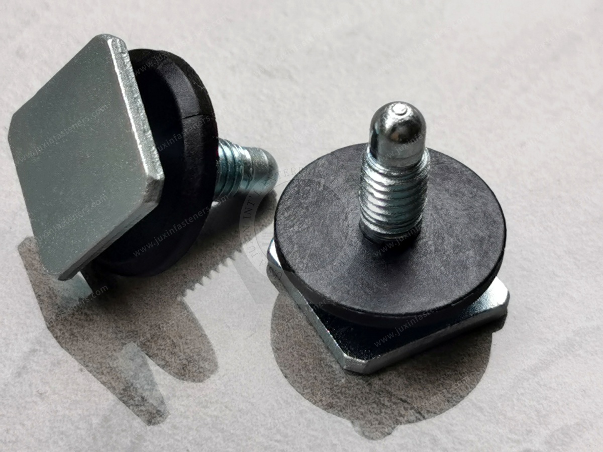
Nylon Rear Spoiler Clip + Automotive Spoiler Slide Bolt
The Slide Bolt may use a special head geometry that engages a mounting slot, track, or channel. Applicable configurations include M5 and M6 sizes,
with representative M6 × 14 and M6 × 20 configurations and applicable property classes such as 8.8 or 10.9.
Surface finishes may include Color Zinc, Zinc-Nickel Alloy, or Black Zinc, depending on the specified configuration.
Some configurations may include a pre-applied thread-locking patch where specified.
The assembly concept can be understood as:
Slide → Position → Engage → Tighten
Whether the geometry provides an anti-rotation effect depends on the mating slot and head design.
Quality inspection therefore needs to consider not only the nominal thread size but also the application-specific geometry and mating interface.
See Automotive Rear Spoiler Fastening Components: Spoiler Bolts and Rear Spoiler Clips.
Automotive fastening systems are not limited to metal components.
Plastic and nylon fasteners are also used in:
interior trim,
exterior trim,
door modules,
electrical and electronic assemblies,
housings,
panels,
clips,
retainers,
and other lightweight applications.
For polymer components, quality verification may focus on different characteristics from metal fasteners, including:
material specification,
molding or forming geometry where applicable,
mounting-hole compatibility,
panel thickness,
retention geometry,
dimensional stability,
installation characteristics,
and application-specific material behavior.
For a broader overview, see Automotive Plastic Fasteners: Types, Applications & OEM Sourcing Guide.
For design considerations involving hole size, retention, tolerance stack-up, and mating geometry, see Automotive Plastic Fastener Design: Hole Size, Retention & Mating Geometry.
The key principle remains the same:
Quality verification must follow the actual function and engineering requirements of the component.
Before approving a supplier, quality and engineering teams can ask:
How are customer drawing revisions controlled?
How are critical-to-function dimensions identified?
How are thread characteristics inspected?
How is the specified material verified?
How is material lot identification maintained where required?
How are surface-treatment requirements controlled?
Which inspection records are available for the project?
How are non-conforming parts controlled?
How are engineering changes communicated?
How are sample and production requirements connected?
How is packaging identification linked to production lots?
Can the supplier provide the inspection documentation specified by the customer?
These questions help move supplier evaluation from general claims toward verifiable process control.
Procurement should look beyond unit price.
A supplier comparison can include:
| Evaluation Area | Questions for Procurement |
|---|---|
| Technical understanding | Can the supplier interpret the drawing and requirements? |
| Manufacturing route | Is the proposed process appropriate for the geometry and volume? |
| Quality control | Are critical characteristics identified and verified? |
| Material control | Can specified material requirements be documented? |
| Traceability | Can production lots be identified where required? |
| Inspection | Is the inspection plan aligned with the customer specification? |
| Documentation | Can required quality documents be provided when agreed? |
| Change control | How are drawing or process changes communicated? |
| Packaging | Can packaging and identification requirements be followed? |
| Supply continuity | Can the supplier support repeat production requirements? |
| Communication | Can engineering and procurement issues be resolved efficiently? |
This provides a more meaningful supplier comparison than simply asking which supplier has the lowest quotation.
Visual inspection is useful, but it cannot replace dimensional or material verification where those characteristics are critical.
Measuring every dimension with the same inspection intensity may increase effort without improving the control of the most important characteristics.
Critical dimensions should be identified first.
“Steel,” “stainless steel,” or “aluminum” may not be sufficient if the engineering drawing specifies a particular grade or condition.
A coating can affect dimensions, thread condition, appearance, friction, or corrosion-related performance depending on the application.
Surface treatment should therefore be included in the technical specification.
If an OEM requires inspection reports, material documents, or lot traceability, those requirements should be established before production.
Drawing revision control should be maintained throughout quotation, sampling, inspection, and production.
A customer-specific component may have requirements that differ significantly from a conventional catalog fastener.
The approved drawing and customer specification remain the primary technical reference.
JUXIN FASTENERS supplies customer-specific and non-standard fastening and precision metal components for industrial and automotive applications.
Depending on the component, manufacturing route, and customer requirements, product categories can include:
Custom screws and bolts
Non-standard fasteners
CNC-machined components
Precision shafts and pins
Bushings and spacers
Washers
Rivets
Rivet nuts
Weld nuts and weld studs
Application-specific automotive components
Plastic and nylon fastening components
For CNC automotive components, customers can provide 2D drawings, 3D CAD files, samples, specifications, and inspection requirements.
Depending on the part, quality verification can include:
Dimensional measurement
Thread inspection
Hole diameter and position verification
Material verification
Hardness testing where specified
Mechanical testing where applicable
Surface-finish verification
Surface-treatment verification
Functional inspection
Batch traceability
Customer-defined inspection documentation
The exact inspection scope should be established according to the component, drawing, application, and customer quality requirements.
A useful JUXIN quality workflow can therefore be represented as:
Customer Drawing → Mating Interface → Material → Geometry → Manufacturing Route → Critical Characteristics → Inspection Method → Documentation → Production Lot → Shipment
This approach connects engineering requirements with procurement execution rather than treating quality as a separate final-stage activity.
Quality should not begin only after production is complete.
A stronger sourcing workflow is:
Review:
dimensions,
tolerances,
GD&T,
material,
threads,
surface treatment,
special notes,
and drawing revision.
Determine whether the component is better suited to:
CNC turning,
CNC milling,
Swiss-type machining,
drilling,
tapping,
threading,
grooving,
turn-mill machining,
cold forming,
stamping,
or another suitable manufacturing route.
Identify which characteristics control:
assembly,
mating,
function,
clearance,
or customer acceptance.
Connect each critical requirement to an appropriate verification method.
Where applicable, samples can be evaluated against the approved drawing and agreed inspection requirements.
Production requirements, inspection requirements, material control, and lot identification should remain aligned with the approved specification.
Packaging, identification, inspection records, and other agreed documentation should accompany the shipment as required by the project.
For engineering and procurement teams, the complete model can be simplified to:
Requirement
↓
Critical Characteristic
↓
Manufacturing Process
↓
Inspection Method
↓
Acceptance Criterion
↓
Inspection Record
↓
Lot Identification
↓
Customer Approval
This model is more useful than simply asking whether a supplier “has quality control.”
It allows the OEM to evaluate whether the supplier's quality process is connected to the actual component requirements.
Custom metal components are often defined by customer-specific geometry, materials, tolerances, interfaces, and application requirements.
A structured quality process helps verify those requirements consistently throughout sampling and production.
Depending on the product and customer specification, relevant frameworks may include ISO, DIN, EN, ASME/ANSI, SAE, and ASTM.
The applicable standard should be determined by the approved drawing or engineering specification rather than added generically.
Where required, lot identification can connect production and inspection records with the material and finished-component lot.
This can support investigation, containment, and corrective-action activities when a quality issue occurs.
Depending on the component, inspection may include dimensional measurement, thread inspection, hole verification, material verification,
hardness testing, mechanical testing, surface-treatment verification, and functional inspection.
The appropriate method depends on the customer-defined requirements.
Not necessarily. Inspection documentation should be defined according to the customer specification, project quality requirements, component risk, and agreed inspection plan.
JUXIN FASTENERS can work with customer-defined inspection and documentation requirements.
The exact documents provided depend on the project agreement and may include dimensional inspection records, material documentation, testing records, or Certificates of Conformance where specified.
Provide the approved drawing or CAD file together with material requirements, surface-treatment requirements, inspection expectations, quantity, packaging requirements, and any applicable customer quality specifications.
This allows the component, manufacturing route, inspection requirements, and commercial quotation to be evaluated together.
For OEMs, Tier-1 suppliers, procurement teams, supplier quality engineers, and engineering departments sourcing customer-specific metal components,
the most effective starting point is the actual component requirement.
Send JUXIN FASTENERS:
2D engineering drawing
3D CAD file where available
Drawing revision
Material specification
Surface-treatment requirement
Critical dimensions or functional requirements
Inspection requirements
Annual or project quantity
Packaging requirements
Applicable international standards
Sample or prototype requirements
JUXIN FASTENERS can then review the component from the perspective of:
Engineering Requirement → Manufacturing Route → Quality Verification → Documentation → Production → OEM Supply
For custom metal components, CNC-machined parts, non-standard fasteners, automotive fastening components, and application-specific mechanical components:
Email: info@juxinfasteners.com
Website: www.juxinfasteners.com
JUXIN FASTENERS — OEM-oriented sourcing for customer-specific fastening and precision component requirements.
 MORE NEWS
Sep. 22, 2026
Sep. 22, 2026
Sep. 22, 2026
Contact Us
Tel.:
+86 020 8621 0320
+86 020 3121 6067
E-mail:
Technical Support:
Navigation
SEND INQUIREY