
Call Us
+86 136 6007 9809
Call Us
+86 136 6007 9809

Jun. 10, 2024
Ex d Enclosure Cover Bolt Design: Blind Holes, Thread Engagement and Joint Integrity
Cover bolts are important structural components in many Ex d flameproof electrical enclosures.
They secure removable covers to the enclosure body and help maintain the assembly configuration required by the approved equipment design.
For enclosure manufacturers, the engineering challenge extends beyond selecting a bolt with adequate tensile strength.
The complete fastening arrangement must account for internal-thread strength, effective engagement, blind-hole depth, enclosure material, joint geometry,
installation conditions and maintenance requirements.
These considerations are particularly important for cast aluminum housings, blind tapped holes and covers that are opened repeatedly during equipment servicing.
An incorrectly selected screw may bottom out before the cover is fully seated. A stronger bolt may overload a weaker internal thread.
An added washer may alter the intended assembly stack-up. Even a dimensionally similar replacement fastener may differ from the approved design.
This guide examines the mechanical design and production considerations of Ex d enclosure cover bolts,
with particular emphasis on blind-hole fastening and threaded connections in aluminum and steel housings.
JUXIN FASTENERS supplies industrial bolts, machine screws, stainless steel fasteners and drawing-based OEM fastening components for technical evaluation against customer specifications.
Ex d Cover Bolt Design and the Approved Enclosure Assembly
An Ex d flameproof enclosure is designed to withstand an internal explosion under specified conditions and prevent flame transmission to the surrounding explosive gas atmosphere.
The enclosure construction may include:
A main housing
A removable cover
A flameproof joint
Cover fastening screws or bolts
Internal threaded holes or other approved fastening arrangements
The relevant protection requirements are addressed by IEC 60079-0 and IEC 60079-1, using the editions applicable to the equipment approval.
Critical Design Principle
A cover bolt cannot be evaluated independently of the enclosure.
Its geometry, material, mechanical properties, engagement and installation requirements must be consistent with the approved construction.
Compliance with a general bolt standard alone does not establish conformity of the complete Ex d assembly.
Why Blind Tapped Holes Require Special Attention
Many enclosure designs use screws installed into blind tapped holes in the housing.
Unlike a through-hole, a blind hole has a closed end.
The screw must achieve the required engagement and joint seating without contacting the bottom of the hole prematurely.
Potential problems include:
Screw bottoming
Incomplete cover seating
Inadequate clamp load
Internal thread damage
Excessive installation torque
Housing damage
These risks become more significant when the design has limited available depth or substantial manufacturing tolerance variation.
Understanding Screw Bottoming
Screw bottoming occurs when the end of the screw contacts the bottom of a blind hole before the intended fastening condition is achieved.
The installation tool may register a high torque even though the cover is not properly clamped.
Why This Is Dangerous
The operator may interpret the torque reading as successful tightening.
In reality, the measured resistance may result from contact at the bottom of the hole rather than the intended joint clamping action.
Engineering Recommendation
Check screw protrusion into the hole, usable hole depth and the complete assembly stack-up.
Do not use final torque alone as proof that a blind-hole cover bolt has seated correctly.
Blind-Hole Depth and Screw Length Calculation
A blind-hole design should distinguish between:
Total drilled hole depth
Fully formed internal-thread depth
Usable engagement depth
Screw penetration
Required bottom clearance
These dimensions are not interchangeable.
The bottom of a drilled blind hole may contain a drill-point region or incomplete threads.
A screw should not be assumed to engage effectively throughout the entire drilled depth.
Practical Stack-Up Review
For a screw installed through a cover into a blind tapped hole, the designer should evaluate:
Screw penetration = screw length under the head − effective cover and interface stack-up
This simplified relationship applies only when screw length is measured from the appropriate head bearing reference and the assembly geometry is correctly represented.
The resulting penetration must be checked against the usable hole depth.
Bottom clearance = available internal hole depth − maximum screw penetration
The clearance calculation must consider dimensional tolerances, incomplete threads and any relevant manufacturing or assembly variations.
A positive calculated clearance under nominal conditions is not sufficient if worst-case tolerances could still cause bottoming.
Important Limitation
There is no universal one-thread bottom-clearance rule suitable for every Ex d enclosure.
The required clearance must be established from the approved drawing, actual geometry and applicable design requirements.
Tolerance Stack-Up in Blind-Hole Fastening
A nominally correct screw may become unsuitable when production tolerances accumulate.
Consider a cover fastening arrangement with variation in:
Screw length
Cover thickness
Recess depth
Housing machining
Thread depth
Surface finish thickness
If the cover becomes thinner while the screw approaches its maximum permitted length, penetration into the blind hole increases.
At the same time, the minimum usable hole depth may decrease because of manufacturing variation.
Engineering Information Gain
The most critical condition is often not the nominal assembly.
It is the combination of maximum screw penetration and minimum usable hole depth.
This should be evaluated before releasing the design for production.
Effective Thread Engagement
Effective thread engagement is the portion of the mating thread that can transfer load between the screw and the enclosure.
The required engagement depends on:
Screw diameter and pitch
Screw mechanical properties
Internal-thread material
Thread tolerance
Applied load
Engagement geometry
Approved enclosure requirements
Why Engagement Length Matters
Insufficient engagement may cause the internal thread to strip before the screw reaches its intended mechanical capacity.
Excessive engagement does not automatically improve the joint if the screw bottoms out or the surrounding housing geometry is inadequate.
Engineering Recommendation
Evaluate the external and internal threads together.
Do not select engagement length from screw diameter alone without considering the mating material and loading conditions.
Bolt Tensile Failure vs. Internal Thread Stripping
These are different failure modes.
Bolt Tensile Failure
The externally threaded fastener fails under tensile loading.
Internal Thread Stripping
The mating internal threads lose their load-carrying capability.
This may occur before bolt tensile failure, particularly when a relatively strong steel screw is installed into a lower-strength housing material.
Practical Design Implication
Increasing bolt strength without reviewing the internal thread may not improve the connection.
It may simply move the critical failure location into the enclosure.
Aluminum Alloy Flameproof Housings
Cast aluminum alloys are used in various industrial enclosure designs because of their weight, corrosion and manufacturing characteristics.
However, the mechanical properties of an aluminum internal thread differ from those of a steel internal thread.
Potential concerns include:
Internal thread stripping
Thread wear
Repeated assembly damage
Local housing cracking
Corrosion at dissimilar-metal interfaces
Design Considerations
Engineers should evaluate:
Housing alloy and material condition
Thread engagement
Local wall thickness
Hole position
Distance from adjacent features
Fastener strength
Maintenance frequency
The required thread design depends on the actual housing material and approved equipment construction.
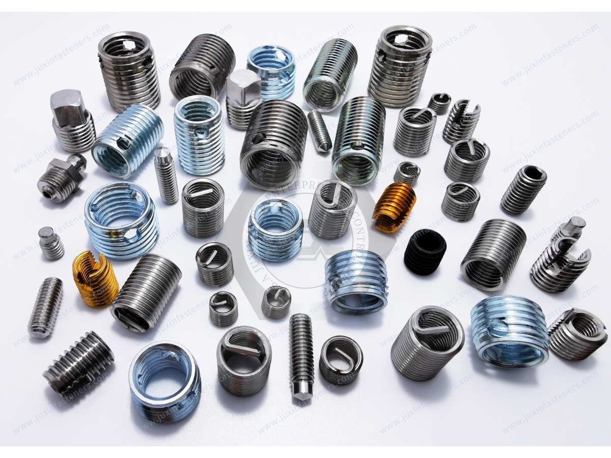
Steel Thread Inserts in Aluminum Housings
Threaded inserts may be considered during the original design of some aluminum components.
Potential engineering objectives include:
Improving internal-thread durability
Supporting repeated assembly
Providing a defined replaceable thread interface
Addressing specific thread-strength requirements
However, the suitability of an insert depends on its design and installation.
Important Ex d Restriction
A steel thread insert must not be introduced into an approved flameproof enclosure as an informal repair or upgrade.
The insert may change the housing construction, thread geometry, material interfaces or other characteristics relevant to equipment approval.
Any proposed insert must be assessed through the appropriate equipment design and conformity process.
Maintenance Consideration
A damaged internal thread in a certified enclosure should be handled according to the equipment manufacturer's approved repair instructions and applicable requirements.
Flat Flanged Flameproof Joints
Some Ex d enclosures use flat flanged joints between the cover and housing.
The approved flameproof joint geometry may include controlled surface dimensions and clearances.
Cover bolts contribute to retaining the assembly in its intended configuration.
Engineering Considerations
Cover stiffness
Bolt distribution
Joint loading
Housing deformation
Mating-surface condition
Approved fastening arrangement
Critical Distinction
The flameproof performance of the joint depends on its approved design and condition.
A higher bolt preload does not compensate for an incorrect flamepath dimension.
Bolt Spacing and Cover Deformation
Bolt arrangement can influence the mechanical response of a cover.
Potential design concerns include:
Uneven load distribution
Local bending
Distortion near bolt holes
Variation in joint closure
Excessive localized stresses
These effects depend on the enclosure geometry, material and loading.
Engineering Recommendation
Evaluate the cover and housing as an assembly rather than selecting bolt size independently.
Spigot and Cylindrical Flameproof Joints
Some flameproof enclosures incorporate spigot or cylindrical joint arrangements.
These geometries may use controlled cylindrical clearances and engagement dimensions as part of the flameproof protection concept.
The cover bolts retain the components in the approved assembled position.
Important Design Principle
The bolt does not replace the dimensional requirements of the flameproof joint.
A cover may appear securely fastened while the joint geometry is outside the approved condition.
Flat Joint vs. Spigot Joint: Fastening Implications
| Design consideration | Flat flanged joint | Spigot or cylindrical joint |
|---|---|---|
| Important geometry | Approved flange surfaces and joint dimensions | Approved cylindrical engagement and clearance |
| Bolt function | Retains cover in the designed position | Retains mating components in the designed position |
| Assembly concern | Cover distortion and surface condition | Alignment, engagement and surface condition |
| Maintenance concern | Damage or contamination of mating surfaces | Damage or contamination of mating surfaces |
| Critical limitation | Tightening cannot correct an invalid flamepath | Tightening cannot correct an invalid flamepath |
The exact requirements depend on the approved equipment design and applicable standard.
Cover Bolt Head Geometry
Possible cover bolt configurations include:
Hexagon head bolts
Socket head cap screws
Other approved machine screw designs
Selection considerations include:
Tool accessibility
Head bearing area
Installation space
Screw strength
Cover geometry
Approved assembly requirements
Engineering Limitation
A hexagon flange bolt should not automatically replace a socket head screw or another specified head style.
Head geometry can affect bearing conditions and the complete assembly.
Washers and Recessed Fastener Arrangements
Some enclosure designs incorporate washers or recessed fastener locations.
These features may influence:
Bearing pressure
Surface protection
Screw penetration
Tool access
Assembly stack-up
Critical Design Rule
Adding or removing a washer changes the assembly geometry.
In a blind-hole design, even a change in washer thickness can alter screw penetration and bottom clearance.
Engineering Recommendation
Treat washers as specified components of the approved assembly, not optional accessories.
Spring Washers and Locking Devices
Potential locking devices include:
Spring washers
Prevailing-torque locking components
Thread-locking materials
Other approved retention features
However, the use of a locking device must be supported by the equipment design.
Important Limitation
Spring washers do not universally prevent vibration-induced loosening.
A thread-locking adhesive does not correct inadequate engagement or damaged threads.
For critical Ex d cover connections, only the approved locking arrangement should be used.
Bolt Tightening Torque and Clamp Load
Tightening torque is an installation control parameter.
It is not a direct measurement of clamp load.
The relationship between applied torque and fastener tension depends on:
Thread friction
Bearing-surface friction
Surface finish
Lubrication
Material
Joint stiffness
Why This Matters in Enclosure Assembly
A change from a zinc-plated screw to a stainless steel screw may alter friction characteristics.
Using the same tightening torque does not necessarily produce the same clamp load.
Over-Tightening Risks
Internal thread stripping
Screw failure
Housing damage
Cover deformation
Damage to bearing surfaces
Under-Tightening Risks
Inadequate mechanical retention
Joint movement
Incomplete assembly condition
Engineering Recommendation
Use the installation torque and procedure established by the equipment manufacturer.
Tightening Sequence
For covers secured by multiple bolts, the tightening sequence may influence load distribution and seating.
The appropriate procedure depends on:
Cover geometry
Number and arrangement of bolts
Joint stiffness
Fastener size
Equipment manufacturer instructions
Production Recommendation
Where the approved assembly procedure specifies staged tightening or a particular sequence, incorporate it into the work instructions.
Do not substitute a generic tightening sequence without validation.
Repeated Opening and Closing
Some electrical enclosures require periodic access for inspection or maintenance.
Repeated disassembly can affect:
Screw threads
Internal threads
Bearing surfaces
Coatings
Joint surfaces
Maintenance Risk
A screw may remain dimensionally recognizable while its threads or bearing surfaces have deteriorated.
Likewise, an internal thread may become damaged after repeated use.
Engineering Recommendation
Establish inspection and replacement criteria according to the equipment manufacturer's requirements.
Fastener Material Selection
Material selection must be consistent with the approved enclosure design.
Carbon Steel and Alloy Steel
These materials may provide mechanical properties appropriate for specified cover bolt designs.
ISO 898-1 may be relevant for applicable carbon steel and alloy steel bolts, screws and studs.
Stainless Steel
Selected stainless steel grades may provide corrosion resistance for suitable environments.
ISO 3506-1 may be relevant to applicable corrosion-resistant stainless steel bolts, screws and studs.
Nickel-Based Alloys
Special alloys may be considered in particular industrial environments when supported by the project specification.
Critical Distinction
A material with greater nominal corrosion resistance or tensile strength is not automatically an approved substitute.
Surface Treatments
Potential finishes include:
Zinc plating
Zinc-nickel plating
Zinc-flake coatings
Black oxide
Stainless steel passivation
Selection depends on the fastener specification and service environment.
Why Finish Changes Require Review
Surface treatment can affect:
Thread fit
Friction
Corrosion behavior
Installation torque
Contact with mating materials
Engineering Recommendation
Do not change the coating of a critical cover bolt without appropriate technical review.
Galvanic Corrosion in Mixed-Material Assemblies
A steel or stainless steel fastener installed in an aluminum housing may create a dissimilar-metal interface.
In the presence of a suitable electrolyte, galvanic corrosion may occur.
The risk depends on:
Material combination
Surface treatments
Environmental exposure
Joint geometry
Moisture retention
Engineering Recommendation
Evaluate corrosion protection at the complete joint level.
Metric and Inch Thread Specifications
Metric threaded fasteners may use relevant ISO thread specifications.
For example:
ISO 261 addresses general-purpose metric thread series.
ISO 965 addresses applicable metric thread tolerances.
Unified inch threads may be specified according to ASME B1.1.
Important Procurement Rule
Metric, UNC, UNF, BSW and BSF thread systems are distinct.
They must not be described as interchangeable based on approximate diameter alone.
For a certified enclosure, the exact approved thread designation must be maintained.
Design Failure Modes and Preventive Reviews
| Failure mode | Potential cause | Required engineering review |
|---|---|---|
| Screw bottoms in blind hole | Excessive penetration | Screw length and usable hole depth |
| Internal thread strips | Inadequate engagement or excessive load | Housing material and thread strength |
| Cover does not seat | Bottoming, obstruction or joint condition | Complete assembly geometry |
| Cover distorts | Excessive or uneven loading | Cover stiffness and fastening arrangement |
| Screw corrodes | Unsuitable material or finish | Environmental compatibility |
| Repeated service damages threads | Wear or incorrect maintenance | Approved service procedure |
| Replacement bolt differs | Material, geometry or coating mismatch | Approved part specification |
| Assembly torque varies | Friction or component variation | Installation process |
| Flameproof joint is damaged | Handling or maintenance damage | Manufacturer-approved inspection and repair |
Production-Line Assembly Controls
For equipment manufacturers, fastener design must translate into a repeatable production process.
Useful controls may include:
Correct part identification
Screw length verification
Thread condition inspection
Approved washer arrangement
Controlled installation torque
Required tightening sequence
Cover seating verification
Inspection records where required
Production Manager Considerations
Incorrect screw lengths or mixed fastener specifications can create repeated assembly defects.
These problems may lead to:
Rework
Damaged housings
Increased inspection time
Production delays
Nonconforming assemblies
Manufacturing Recommendation
Separate critical enclosure fasteners from ordinary internal mounting hardware in work instructions and material handling.
Fastener Quality Inspection
Incoming inspection may include:
Thread dimensions
Screw length
Head geometry
Material specification
Mechanical properties
Surface finish
Visual condition
For drawing-based fasteners, additional inspection characteristics may be specified.
Important Quality Distinction
Dimensional conformity of a bolt does not independently establish conformity of the completed Ex d enclosure.
The equipment manufacturer remains responsible for evaluating the complete approved construction.
OEM Supplier Qualification
Procurement teams sourcing Ex d enclosure cover bolts should review both technical and commercial requirements.
Technical Qualification
Approved drawing
Thread specification
Length and tolerances
Head geometry
Material
Mechanical property class
Surface finish
Required documentation
Manufacturing Compatibility
Assembly equipment
Installation torque
Mating housing material
Thread engagement
Inspection requirements
Commercial Evaluation
MOQ
Sample requirements
Initial order volume
Annual forecast
Packaging
Lead time
Delivery schedule
Second-Source Approval
A second-source fastener should not be accepted solely because it has the same nominal thread diameter and length.
Differences in mechanical properties, coating, geometry or dimensional tolerance may affect the approved assembly.
Procurement Recommendation
Establish the customer's required qualification and change-control process before approving a substitute.
Relevant Industrial Applications
Oil and Gas
Flameproof electrical junction boxes
Instrument enclosures
Hazardous-area control equipment
Chemical Processing
Approved flameproof control housings
Electrical instrumentation enclosures
Process monitoring equipment
Mining
Explosion-protected electrical housings
Equipment control enclosures
Approved motor and instrumentation assemblies
Industrial Automation
Hazardous-area control systems
Electrical connection enclosures
Approved equipment housings
Electrical Equipment Manufacturing
Ex d cover assemblies
Cast aluminum enclosures
Steel enclosure structures
Custom industrial fastening components
Application Limitation
Not every electrical cabinet, EV battery enclosure, rail equipment housing or industrial control box is an Ex d enclosure.
The relevant equipment protection concept must be established before applying Ex d cover bolt requirements.
Engineering Checklist Before Releasing a Cover Bolt Drawing
Before finalizing a cover bolt specification, verify the following:
Geometry
Screw diameter and pitch
Screw length
Head style
Cover thickness
Hole depth
Effective engagement
Bottom clearance
Materials
Screw material
Housing material
Mechanical properties
Surface finish
Corrosion compatibility
Joint Design
Approved flameproof joint geometry
Cover stiffness
Fastener distribution
Bearing conditions
Washer arrangement
Assembly
Tightening torque
Tightening sequence
Installation tools
Seating verification
Maintenance procedure
Quality and Approval
Approved drawings
Inspection criteria
Applicable IEC requirements
Equipment certification constraints
Supplier change control
Frequently Asked Questions
Why must a cover bolt not bottom out in a blind hole?
Bottoming can create installation resistance before the intended joint clamp load is achieved, potentially leaving the cover improperly seated.
How much bottom clearance is required?
The required clearance depends on the approved geometry, usable hole depth, screw penetration and tolerance stack-up. A universal value should not be assumed.
How is thread engagement selected for an aluminum housing?
The designer must consider screw strength, aluminum material properties, thread geometry, loading and the approved enclosure design.
Can a steel threaded insert improve an aluminum internal thread?
An insert may be considered during an appropriately assessed design, but it must not be added to an approved Ex d housing without the required authorization.
Can a stronger bolt compensate for a short engagement length?
Not necessarily. The internal thread may become the limiting component.
Can a flange bolt replace a socket head cover screw?
Only if the substitution is permitted through the applicable equipment approval process.
Do spring washers guarantee that cover bolts will not loosen?
No. Their use and effectiveness depend on the approved fastening arrangement.
Can stainless steel bolts replace alloy steel cover bolts?
Not automatically. Mechanical properties, installation characteristics and approved specifications must be reviewed.
Does passing a bolt tensile test prove that an Ex d enclosure is safe?
No. Fastener testing and complete enclosure conformity are separate matters.
What should be included in an OEM cover bolt RFQ?
The approved drawing, thread, length, head geometry, material, finish, quality requirements, assembly constraints and purchasing forecast.
JUXIN FASTENERS: Drawing-Based Cover Bolts and Industrial Fasteners
JUXIN FASTENERS supplies industrial fastening components for international OEM equipment manufacturing.
Relevant products include:
Hexagon bolts
Socket head cap screws
Machine screws
Stainless steel screws
Carbon steel and alloy steel fasteners
Hexagon flange bolts
Threaded studs
Selected threaded inserts
Drawing-based custom fastening components
For Ex d enclosure applications, fastener requirements must be reviewed against the equipment manufacturer's approved design.
Any proposed changes affecting critical fastening components require the appropriate technical and conformity assessment.
Request an Ex d Enclosure Cover Bolt Drawing Review and RFQ
If your company manufactures flameproof electrical enclosures, cast aluminum control housings, industrial junction boxes or hazardous-area instrumentation equipment,
JUXIN FASTENERS welcomes your fastening component requirements.
For efficient technical review, provide:
Approved bolt drawing + housing material + blind-hole dimensions + thread engagement requirements + mechanical property class + surface finish + annual purchasing volume
Where relevant, include the equipment protection concept, applicable standard edition and customer-specific inspection requirements.
JUXIN FASTENERS can review the submitted fastening specifications and discuss suitable standard or drawing-based supply options.
Final enclosure conformity, approval of design changes and authorization of replacement fasteners remain subject to the equipment manufacturer's applicable approval process.
Company: JUXIN FASTENERS
Website: https://www.juxinfasteners.com/
Email: info@juxinfasteners.com
Send your enclosure cover bolt drawings and OEM RFQ requirements to JUXIN FASTENERS for technical evaluation and quotation.
Contact Us
Tel.:
+86 020 8621 0320
+86 020 3121 6067
E-mail:
Technical Support:
Navigation
SEND INQUIREY



