
Call Us
+86 136 6007 9809
Call Us
+86 136 6007 9809

Nov. 03, 2023
DIN 94 split pins, commonly called cotter pins in North American engineering terminology, are simple but important mechanical retaining components used to secure nuts,
clevis pins, shafts, linkages and other assemblies against unintended disengagement.
Unlike friction-based locking devices, a split pin can provide positive mechanical retention when it passes through a correctly designed cross-hole and is properly installed.
This makes split pins useful in automotive, agricultural machinery, construction equipment, industrial machinery, material-handling systems and other mechanical assemblies where visible and mechanically defined retention is required.
However, selecting a split pin is not simply a matter of choosing a diameter from a catalog.
The real engineering relationship is:
retained component → cross-hole → split-pin diameter → pin length → installation clearance → leg bending → material → corrosion environment → inspection
JUXIN FASTENERS supplies DIN 94 split pins, cotter pins, stainless steel split pins,
retaining pins and custom wire-formed fastening components for OEM and industrial sourcing projects based on standards, customer drawings, samples and application requirements.
A DIN 94 split pin is a formed-wire retaining component consisting of two legs joined at an eye.
During installation, the pin passes through a compatible cross-hole in a bolt, clevis pin, shaft or similar component.
The protruding legs are then bent into the required installed position to prevent the pin from backing out.
Typical functions include:
Retaining slotted or castle nuts
Securing clevis pins
Retaining shafts and linkage pins
Preventing axial disengagement
Providing secondary mechanical retention
Creating a visually inspectable locking feature
The important distinction is that the split pin is usually a retaining or locking element, not the primary load-carrying threaded fastener.
Its function must be understood within the complete assembly.
DIN 94 is a widely recognized German standard for split pins.
ISO 1234 is an international standard covering split pins.
In international sourcing, drawings and purchasing specifications may reference DIN 94, ISO 1234 or customer-specific requirements.
Procurement teams should not automatically assume that every product sold commercially as a “cotter pin” conforms to DIN 94 or ISO 1234.
For sourcing purposes, the RFQ should identify the required standard or drawing explicitly.
Where an existing OEM part is being replaced, verify:
Referenced standard
Nominal size
Length
Material
Surface finish
Cross-hole geometry
Application requirements
Drawing revision where applicable
This prevents a generic commercial cotter pin from being substituted for a drawing-controlled component without technical review.
Terminology varies by region.
In much of Europe and international engineering documentation, split pin is commonly used.
In North America, cotter pin is a common term for the same general type of two-leg bent-wire retaining pin.
“Cotter” can also describe other mechanically different retaining devices, so the product geometry or applicable standard should always be confirmed.
For SEO and international procurement purposes, this page uses both DIN 94 split pin and cotter pin, while the engineering specification remains tied to the actual part.
One of the best-known applications combines a split pin with a slotted or castle-style nut and a cross-drilled bolt or shaft.
The sequence is generally:
Assemble the threaded joint according to the applicable procedure.
Align an appropriate nut slot with the cross-hole.
Insert the split pin through the aligned features.
Seat the eye correctly.
Bend the legs into the specified installed position.
Inspect the completed retention.
Once installed, the pin forms a physical obstruction to unintended nut rotation beyond the available clearance.
This is different from a prevailing-torque nut, thread-locking adhesive or friction-based locking washer.
The split pin provides a geometric mechanical stop.
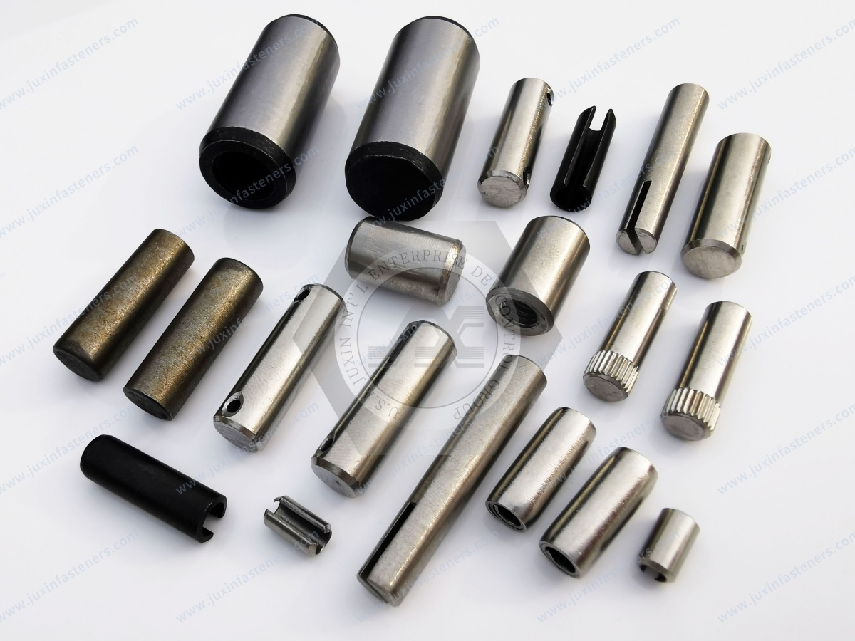
This distinction is important in mechanical design.
A split pin can prevent a retained component from moving beyond a defined mechanical limit, but it does not create the preload of a bolted joint.
For a castellated or slotted-nut assembly, the bolt or nut system still needs to establish the required joint condition.
The split pin then provides mechanical retention.
Therefore, engineers should not treat the split pin as a substitute for correct:
Bolt sizing
Nut selection
Tightening procedure
Joint preload
Bearing design
Fatigue design
The complete joint must perform correctly before the retention feature is considered.
Split-pin selection should start from the mating assembly rather than from the pin alone.
Important parameters include:
Cross-hole diameter
Pin nominal diameter
Required pin length
Bolt or shaft diameter
Nut geometry where applicable
Material thickness around the hole
Available installation space
Space for bending the legs
Required installed orientation
The selected pin must fit the cross-hole while still allowing practical installation and secure retention.
The cross-hole is a functional part of the retaining system.
If the hole is too small, the split pin may:
Be difficult to install
Become damaged during insertion
Require excessive force
Fail to seat correctly
If the hole is unnecessarily large relative to the selected pin, the assembly may have excessive movement or poor positional control.
The hole should therefore be specified according to the applicable standard, drawing and functional requirements.
For custom assemblies, engineers should review the pin and hole as one interface.
Split-pin length must provide enough material beyond the cross-hole to achieve the required installed leg configuration.
The correct length depends on:
Diameter of the bolt, shaft or clevis pin
Width of the retained assembly
Nut geometry
Hole position
Required leg bend
Surrounding clearance
A longer split pin is not automatically safer.
Excessive length can interfere with nearby components, rotating equipment, covers or service access.
Insufficient length can prevent proper leg bending and retention.
The objective is the correct installed geometry, not maximum pin length.
Material selection should consider both manufacturing requirements and service conditions.
A split pin needs sufficient ductility for installation while maintaining the required retaining function.
Depending on the specification, materials may include:
Carbon steel
Stainless steel
Copper
Brass
Other specified alloys
The correct material depends on the application and customer requirements.
Carbon steel split pins are widely used in general mechanical and industrial assemblies.
Depending on the specification, surface protection may be applied to address corrosion requirements.
Possible considerations include:
Indoor or outdoor use
Humidity
Exposure to road environments
Contact with chemicals
Required service life
Mating materials
Material and coating should be specified separately rather than assuming all carbon-steel split pins have the same corrosion performance.
Stainless steel split pins may be selected for applications requiring corrosion resistance or compatibility with stainless assemblies.
Depending on the project specification, suitable stainless grades may include A2 or A4 stainless steel families.
Selection should consider:
Exposure environment
Mating materials
Chloride exposure
Temperature
Mechanical requirements
Customer specification
A4 stainless steel may provide advantages in certain chloride-containing environments compared with common A2 grades,
but it should not automatically be described as universally suitable for every marine or corrosive application.
The actual environment still needs to be evaluated.
Copper- or brass-based split pins may be specified for particular applications where their material properties are useful.
Possible considerations can include:
Electrical characteristics
Corrosion behavior in the actual environment
Non-ferrous material requirements
Magnetic requirements
Assembly compatibility
However, material names alone do not establish suitability.
For example, “brass” should not automatically be treated as a universal marine solution.
The alloy, environment and mating materials should be reviewed.
Where carbon steel is used, surface treatment may be specified according to the required environment and assembly.
Depending on the drawing and manufacturing route, possible systems can include:
Zinc-based coatings
Zinc-nickel systems
Phosphate or black finishes
Other customer-specified coatings
Coating selection should consider more than appearance.
Relevant factors include:
Corrosion requirement
Coating thickness
Dimensional effect
Bending during installation
Coating integrity after deformation
Mating-material compatibility
Because the split-pin legs are bent during installation, the coating system should be considered in relation to the actual installed condition.
A common mistake is to describe a good split pin primarily as “high strength.”
That is incomplete.
A split pin must be capable of being formed during manufacturing and bent during installation without unacceptable cracking or fracture.
Therefore, important material characteristics can include:
Ductility
Formability
Appropriate hardness
Material consistency
Surface condition
An excessively brittle component may be unsuitable even if the base material has high nominal strength.
The objective is controlled deformation with reliable retention.
For critical applications, a previously installed and bent split pin should generally not be assumed suitable for reuse unless the applicable maintenance procedure explicitly permits it.
Installation plastically deforms the legs.
Straightening and rebending can change the condition of the pin and may introduce damage.
For service and maintenance planning, split pins are therefore commonly treated as inexpensive replacement components.
The governing OEM maintenance procedure or engineering specification should always take precedence.
Automotive and transportation systems may use split pins where positive mechanical retention is required.
Depending on vehicle and component design, applications can include:
Steering linkages
Suspension-related joints
Clevis connections
Axle-related assemblies
Mechanical linkages
Trailer hardware
Serviceable pin joints
The use of a split pin in a safety-relevant assembly does not mean that the pin itself carries the primary structural load.
The main joint components must carry the designed loads, while the split pin performs its specified retention function.
Automotive fastener selection should always follow the vehicle or component engineering specification.
Agricultural equipment frequently contains clevis joints, shafts, linkages and removable mechanical connections.
Split pins can be useful in:
Tractor linkages
Implements
Control mechanisms
Pin joints
Equipment attachments
Adjustment mechanisms
Agricultural environments may include dirt, moisture, fertilizers and outdoor exposure, making material and coating selection important.
Serviceability is also relevant because some components are regularly removed or adjusted.
Construction machinery can contain large numbers of mechanical pins, linkages and retaining systems.
Potential applications include:
Mechanical linkage retention
Clevis connections
Control mechanisms
Equipment attachments
Pin-and-shaft assemblies
The retaining pin should be selected according to the actual equipment design.
For heavily loaded pin joints, the split pin generally retains the main pin rather than carrying the primary joint load itself.
Industrial equipment applications may include:
Linkages
Actuation systems
Shafts
Clevis assemblies
Mechanical controls
Adjustable mechanisms
Safety retention points
For rotating or moving machinery, installed leg orientation and surrounding clearance can be particularly important.
An incorrectly positioned split pin can interfere with nearby components even when its diameter and length are technically correct.
Material-handling and transportation systems frequently use mechanical pins and linkages that may require secondary retention.
Applications can include:
Equipment linkages
Trailer components
Lifting-related mechanisms
Hinged connections
Removable shafts
Control mechanisms
Selection should consider vibration, impact, corrosion and maintenance frequency.
Split pins and R-clips can both retain pins or shafts, but they are not equivalent.
A split pin is installed through a cross-hole and its legs are bent to retain it.
An R-clip is designed for quick insertion and removal and generally does not require permanent bending during installation.
Considerations include:
Required security
Service frequency
Removal frequency
Installation access
Vibration
Risk of accidental disengagement
For frequently removed connections, an appropriate reusable retaining device may be preferable.
For other applications, a bent split pin may provide a more deliberate retention method.
A split pin and a spring pin perform fundamentally different functions.
A split pin/cotter pin is typically used as a retaining device through a cross-hole.
A spring pin is an interference-fit pin installed into a hole and may be used for locating, joining or load transfer depending on the design.
They should not be treated as substitutes simply because both products are called “pins.”
Both can be used in mechanical retention strategies, but the design, installation process and application logic are different.
A split pin relies on a defined cross-hole and bent legs.
Safety wire uses wire routing and twisting according to an appropriate procedure.
The correct method depends on the equipment design and governing engineering or maintenance requirements.
Understanding potential failure modes helps engineers design better retaining systems.
Excessive clearance can reduce positional control and may create undesirable movement.
Installation may damage the pin or make correct seating difficult.
The legs may not provide the required installed bend.
The legs may interfere with adjacent components or moving parts.
Possible causes include unsuitable material condition, excessive hardness, manufacturing defects or inappropriate installation.
The selected material or coating may be unsuitable for the environment.
Improper bending can create interference or inadequate retention.
Repeated bending can damage the component and should not be assumed acceptable for critical applications.
Installation instructions should follow the equipment drawing or applicable maintenance procedure.
General engineering considerations include:
Verify the correct pin size and material.
Inspect the pin and mating cross-hole.
Insert the pin fully into the intended position.
Confirm correct seating of the eye.
Bend the legs according to the specified installation method.
Ensure the legs do not interfere with adjacent or moving components.
Inspect for cracks or installation damage.
There is no single leg-bending configuration that should automatically be applied to every assembly.
The required installed geometry depends on the joint design.
A piece of wire may fit through the same hole, but that does not make it functionally equivalent to a specified split pin.
Unknown wire may differ in:
Material
Diameter
Ductility
Surface condition
Fatigue behavior
Corrosion resistance
Dimensional consistency
For engineered assemblies, the specified retaining component should be used.
Inspection requirements should follow the applicable standard, drawing and customer specification.
Depending on the project, controls may include:
Diameter
Length
Eye geometry
Leg geometry
Surface condition
Material verification
Coating requirements
Burr control
Cracks or harmful defects
Packaging
Lot identification where required
For custom components, additional dimensions or functional requirements may be defined on the customer drawing.
Standard DIN 94 split pins are suitable where the standard geometry meets the assembly requirement.
Custom designs may be needed when a project requires:
Non-standard diameter
Special length
Different eye geometry
Customer-specific material
Special surface treatment
Unique leg configuration
Restricted installation envelope
Existing OEM replacement
Drawing-controlled geometry
A custom component should be based on the actual assembly requirement rather than changing a standard part unnecessarily.
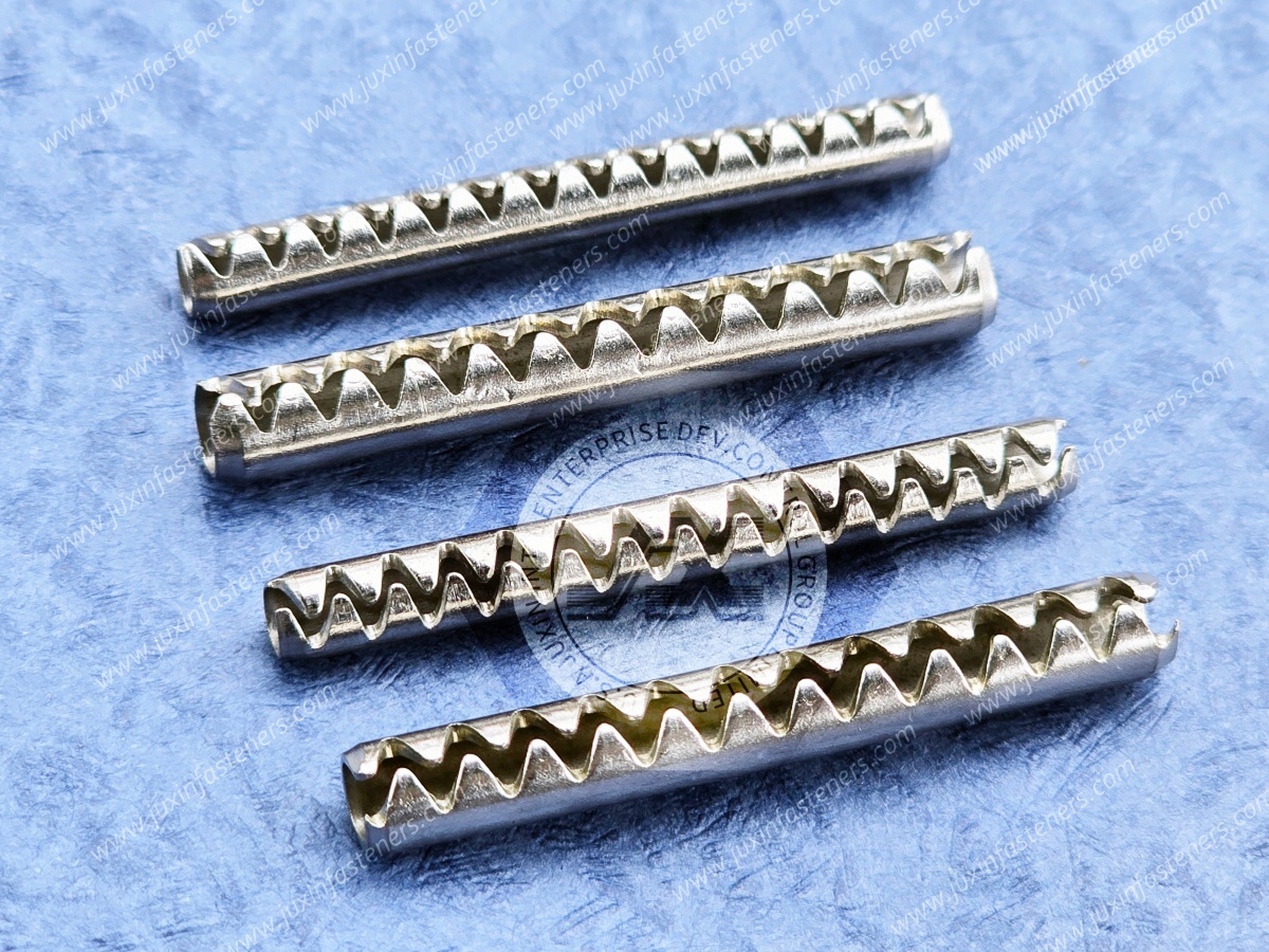
Split pins appear simple, but second-source qualification should still confirm functional equivalence.
A practical process includes:
Identify whether the existing component is controlled by DIN 94, ISO 1234 or a customer-specific drawing.
Check diameter, length, eye geometry and other specified features.
Do not substitute materials solely on appearance.
Verify the coating or surface condition required by the application.
Where possible, understand the cross-hole and installation geometry.
Confirm fit, installation and bending behavior in the actual assembly.
Define inspection and documentation according to the sourcing requirement.
This is especially useful for OEMs developing alternative sources for high-volume retaining components.
For accurate technical review and quotation, provide:
DIN 94 or ISO 1234 reference where applicable
Nominal diameter
Length
Material
Stainless grade where applicable
Surface treatment
2D drawing for custom designs
Physical sample where available
Cross-hole information for special applications
Application environment
Required inspection
Required documentation
Sample quantity
Production quantity
Estimated annual demand
Packaging requirements
For custom or legacy parts, a drawing and physical sample can improve technical review.
In many commercial contexts, yes: the DIN 94 split pin is commonly called a cotter pin, particularly in North America.
However, purchasing documentation should reference the required standard or drawing to avoid terminology-related confusion.
They cover the same general product category, but procurement teams should follow the exact standard or drawing specified by the customer rather than assuming automatic interchangeability.
The correct material depends on the mechanical requirement, environment, mating materials, corrosion requirement and customer specification.
Carbon steel and stainless steel are common choices, but there is no universal material for every application.
They can be suitable for many outdoor environments, but the correct stainless grade should be selected according to the actual exposure conditions and mating materials.
When correctly integrated with a suitable slotted or castle-nut and cross-hole design, the split pin can mechanically limit unintended nut rotation or disengagement.
It does not replace correct joint tightening or preload design.
A previously bent split pin should not automatically be reused, particularly in critical assemblies. Follow the applicable OEM or maintenance procedure.
JUXIN FASTENERS supports standard and custom split-pin and retaining-component projects based on customer drawings, samples, materials and application requirements.
The split pin is one of the simplest components in a mechanical assembly, but reliable retention still depends on correct interface design.
A practical engineering selection path is:
retention function → mating component → cross-hole → pin diameter → pin length → material → surface protection → installation geometry → inspection
For procurement and supplier-development teams, the sourcing path becomes:
standard/drawing → material → finish → sample → assembly verification → production control
This approach provides more useful engineering information than selecting a cotter pin solely by nominal diameter and price.
JUXIN FASTENERS supplies DIN 94 split pins, cotter pins, stainless steel split pins, retaining components,
custom pins and drawing-based fasteners for automotive, agricultural machinery, construction equipment, industrial machinery and global OEM applications.
For standard products, custom dimensions, existing-part replacement or second-source development, send your specification, drawing or physical sample for technical review and quotation.
JUXIN FASTENERS
FASTENING SOLUTIONS FOR GLOBAL OEMS
Website: www.juxinfasteners.com
Email: info@juxinfasteners.com
 MORE NEWS

Sep. 27, 2026

Sep. 27, 2026

Sep. 27, 2026
Contact Us
Tel.:
+86 020 8621 0320
+86 020 3121 6067
E-mail:
Technical Support:
Navigation
SEND INQUIREY