
Call Us
+86 136 6007 9809
Call Us
+86 136 6007 9809

Sep. 23, 2023
DIN 472 internal retaining rings, also known as internal circlips, internal snap rings or retaining rings for bores, provide compact axial retention for components installed inside machined bores and housings.
Unlike an external retaining ring installed in a groove on a shaft, a DIN 472 internal retaining ring is compressed during installation, inserted into the bore and released into an internal groove.
Once correctly seated, the ring forms a mechanical shoulder that can help prevent axial displacement of components such as:
rolling bearings;
bushings;
gears;
sleeves;
pistons;
spacers;
mechanical subassemblies.
DIN 472 retaining rings are widely used in industrial machinery, automotive assemblies, gearboxes, pumps,
hydraulic and pneumatic equipment, power-transmission systems, robotics and precision mechanical equipment.
However, successful retaining-ring design requires more than selecting a ring from the nominal bore diameter.
The correct engineering system is:
Retaining Ring + Groove + Housing + Retained Component + Axial Load + Installation Process
The ring cannot be evaluated independently from the groove and surrounding assembly.
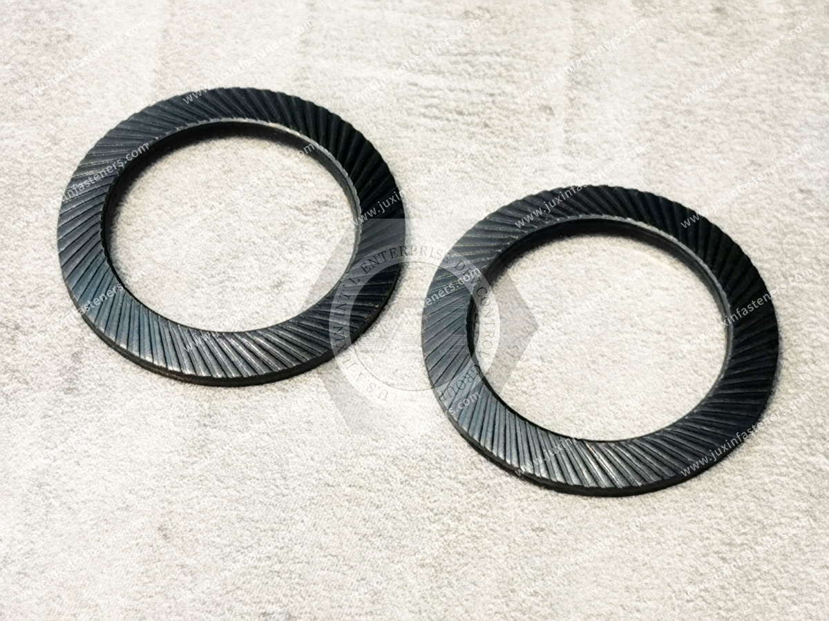
DIN 472 specifies retaining rings for bores and their corresponding grooves.
The current DIN 472:2026-05 standard covers normal and heavy types.
The primary function of the retaining ring is axial location and retention of components inside an appropriately designed bore.
A common example is a rolling bearing installed into a housing bore.
After the bearing reaches its intended axial position, a retaining ring installed in a groove can create a mechanical stop against movement in the axial direction.
This produces a compact assembly without requiring a threaded retaining nut or a separate bolted end plate in suitable applications.
DIN 472 and DIN 471 are frequently confused in sourcing inquiries.
The fundamental distinction is straightforward.
DIN 472 retaining rings are designed for bores.
The ring is compressed during installation so that it can enter the bore and then expand into the internal groove.
DIN 471 retaining rings are designed for shafts.
The ring is expanded during installation, passed over the shaft and released into an external shaft groove.
A useful purchasing rule is:
DIN 472 = Bore / Internal Retaining Ring
DIN 471 = Shaft / External Retaining Ring
The two products are not interchangeable.
The retaining mechanism is sometimes described too simply as the ring “locking” a component in place.
The actual load path is more important.
When the retained component pushes axially against the ring, load can be transferred through:
Retained Component → Retaining Ring → Groove Flank → Housing
This means the complete assembly depends on more than ring strength.
Important variables include:
ring geometry;
groove geometry;
groove diameter;
groove width;
groove location;
housing material;
housing wall thickness;
retained-component geometry;
bearing/contact area;
axial load magnitude;
load direction;
static or dynamic loading.
Therefore:
Retaining Ring Strength ≠ Complete Assembly Strength
A high-quality DIN 472 ring installed in an incorrect groove can still fail.
The groove creates the mechanical interface through which axial load is transferred into the housing.
An unsuitable groove may contribute to:
incomplete ring seating;
excessive ring movement;
groove-edge deformation;
housing material failure;
ring displacement;
reduced axial capacity.
For this reason, DIN 472 should be treated as a ring-and-groove system rather than simply a ring dimensional catalogue.
An RFQ that says:
“DIN 472, 40 mm”
identifies an important size parameter, but it may not answer every engineering question required for an OEM application.
The purchasing and engineering teams should also consider:
normal or heavy type where applicable;
groove dimensions;
housing material;
retained component;
axial loading;
environment;
surface requirement;
installation process.
DIN 472 covers normal and heavy types.
The correct choice should be based on the applicable DIN 472 dimensional system and the requirements of the assembly.
A heavy-type ring should not simply be described as “better” or universally stronger for every application.
Increasing ring section or changing ring geometry can also affect:
groove requirements;
installation force;
available radial space;
plier access;
surrounding housing geometry.
The selected type must match the actual assembly.
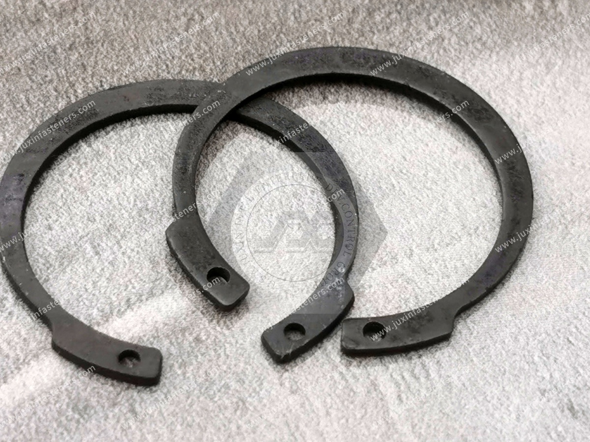
A typical DIN 472 internal retaining ring includes:
curved ring body;
open ends;
installation lugs;
plier holes.
During installation, circlip pliers engage the holes and compress the ring.
This temporarily reduces its outside diameter sufficiently for insertion into the bore.
Once aligned with the groove, the pliers are released and the ring expands into its installed position.
After installation, engineers and assembly personnel should confirm that the ring has entered the groove correctly around the required circumference.
Incomplete seating can create an unsafe assumption that the component has been retained when the ring has not reached its intended working position.
Possible causes include:
incorrect groove geometry;
contamination;
burrs;
excessive ring deformation;
incorrect ring size;
unsuitable installation tooling.
Spring steel is used because the ring must elastically deform during installation and recover sufficiently to engage the groove.
However, this should not be interpreted as meaning the ring is a vibration absorber.
The spring characteristic primarily supports:
installation deformation;
elastic recovery;
groove engagement.
It does not automatically:
damp system vibration;
absorb all shock loads;
eliminate impact;
compensate for an incorrect groove;
guarantee fatigue life.
Another important distinction is between axial and radial forces.
DIN 472 retaining rings are principally used for axial retention of components within bores.
The ring is not a universal solution for every multidirectional load acting on an assembly.
If the retained component experiences complex:
radial load;
axial load;
impact;
oscillation;
vibration;
cyclic loading,
the complete load path must be evaluated.
A ring that performs correctly under a static axial load should not automatically be assumed to provide identical reliability under repeated dynamic loading.
Dynamic applications can introduce:
repeated groove loading;
fretting;
cyclic deformation;
impact;
ring movement;
fatigue-related mechanisms.
The actual duty cycle should therefore be included in engineering validation for critical applications.
When the retained component applies axial force to the ring, the ring transfers force into the groove.
This can create localized contact stresses.
Depending on the assembly, potential limiting mechanisms may include:
ring deformation;
groove-flank deformation;
housing material yielding;
groove-edge failure.
Therefore:
The Strongest Ring Does Not Automatically Produce the Strongest Retaining Assembly
The same DIN 472 retaining ring may behave differently when installed in different housing materials.
Examples include:
hardened steel;
carbon steel;
stainless steel;
cast iron;
aluminum alloy.
A relatively soft housing material may become the limiting part of the load path before the retaining ring reaches its own material limit.
Lightweight machinery, EV systems, robotics and industrial electronics may use aluminum housings.
When a steel retaining ring is installed into an aluminum groove, engineering evaluation should consider:
groove strength;
local bearing stress;
edge deformation;
cyclic loading;
corrosion environment;
material compatibility.
Simply selecting a stronger steel ring does not automatically strengthen the aluminum groove.
The amount of material surrounding the groove can also influence assembly behavior.
A groove located too close to a housing edge or within an insufficiently supported wall may create a different load path from the same groove inside a thick housing.
The complete housing geometry should therefore be reviewed for load-critical applications.
The face of the bearing, bushing, gear or sleeve that contacts the retaining ring influences load transfer.
Contact should be considered as part of the complete mechanical design.
A nominally correct ring cannot compensate for an unsuitable retained-component interface.
DIN 472 retaining rings are also used because the groove establishes a defined axial stop.
The groove location therefore contributes directly to:
component position;
axial clearance;
assembly stack-up.
For precision machinery, groove-position tolerance can be just as important as ring dimensional accuracy.
Some assemblies require controlled axial clearance rather than a completely rigid stack.
Engineers should distinguish between:
retaining a component against escape;
accurately locating the component;
controlling end play;
preloading the component.
A retaining ring does not automatically perform all four functions.
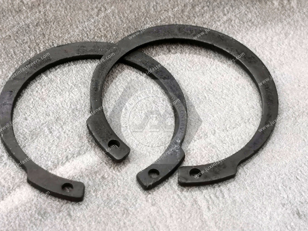
Bearing retention is one of the most common applications for internal circlips.
Potential assemblies include:
gearbox housings;
electric motors;
pumps;
industrial drives;
machine-tool assemblies;
conveyor drives.
The retaining ring may provide an axial stop for the bearing outer ring.
However, bearing-system design must also consider the intended fixed/floating bearing arrangement, thermal expansion and bearing manufacturer's recommendations.
A DIN 472 ring can establish an axial stop.
That does not mean it automatically generates or controls bearing preload.
Where bearing preload is required, the complete bearing arrangement must be designed accordingly.
Spring steel is widely used for retaining rings because the component must withstand controlled elastic deformation during installation.
For OEM sourcing, the material requirement should follow the applicable product specification, customer drawing and service environment.
Avoid specifying a material only because it is commonly used in another retaining-ring application.
Spring-steel rings can provide the combination of:
strength;
elastic behavior;
manufacturability;
dimensional stability
required for many industrial applications.
The final performance depends on the complete material condition and manufacturing process, not simply the material name.
Corrosion-resistant retaining-ring materials may be considered for applications involving:
humidity;
washdown;
outdoor exposure;
chemical environments;
food equipment;
laboratory equipment;
marine-related conditions.
However:
Stainless Steel ≠ Corrosion-Proof
The correct stainless material should be selected according to the actual service environment and customer specification.
The original article named one stainless grade as though it were a universal DIN 472 corrosion-resistant option.
For an OEM engineering page, that is too restrictive.
Material selection should instead be based on:
current DIN 472 requirements;
required mechanical properties;
corrosion environment;
installation deformation;
customer specification.
Hardness is relevant to retaining-ring material performance, but hardness values should be interpreted according to:
ring material;
product dimensions;
applicable DIN 472 edition;
specified test method.
For current production orders, the requirements of the applicable DIN 472:2026-05 specification and customer drawing should control.
Where Vickers hardness testing is specified, ISO 6507-1:2023 defines the Vickers hardness test method for metallic materials within its scope.
Hardness test requirements should not be confused with hardness conversion.
ISO 18265:2013 provides principles and tables for converting hardness values between specified hardness scales and, in some cases, estimating tensile strength.
The standard was reviewed and confirmed in 2024 and remains current.
However, converted values are not substitutes for measurements using the required hardness test method.
Therefore:
Hardness Conversion ≠ Product Acceptance Test
unless the applicable specification explicitly permits the intended use.
Surface requirements should be specified according to:
ring material;
environment;
corrosion requirement;
assembly process;
customer specification.
Spring-steel retaining rings may be supplied with appropriate protective surface systems depending on the application.
Dark conversion finishes with oil protection are commonly encountered on industrial retaining rings.
They can provide handling and storage protection appropriate to certain environments.
However, they should not automatically be interpreted as high-corrosion-resistance systems.
It is too broad to state that zinc coatings are universally prohibited on retaining rings.
Where electroplated coatings are considered for high-strength spring components, the material condition, manufacturing process and hydrogen-embrittlement risk require appropriate control.
The correct coating decision should come from the applicable product specification and customer requirement rather than a blanket rule.
Non-electrolytic coating systems may be considered for some applications where appropriate.
However, coating selection must consider:
dimensional effects;
deformation during installation;
adhesion;
corrosion requirement;
friction/contact behavior;
customer specification.
No coating should be selected solely from a generic salt-spray-hour target.
Where corrosion testing is required, laboratory salt-spray testing can be useful for comparing specified coating systems under controlled conditions.
But salt-spray hours should not be converted directly into years of field service.
Real service life depends on:
environment;
temperature;
moisture;
contaminants;
installation damage;
galvanic interfaces;
maintenance.
For susceptible high-strength spring-steel components, hydrogen introduced during certain manufacturing or surface-treatment processes can create embrittlement risk.
The risk depends on factors including:
material;
hardness;
process;
hydrogen exposure;
applied stress.
There is no universal baking recipe that guarantees elimination of hydrogen-embrittlement risk for every retaining ring.
OEM inspection can include dimensions relevant to the applicable standard and drawing.
Depending on the component and inspection plan, these may include:
ring dimensions;
thickness;
lug geometry;
plier holes;
functional fit.
The inspection plan should be tied to the controlled product specification.
For retaining rings, dimensional compliance should ultimately support correct assembly into the specified groove.
Functional checks may therefore be valuable when defined by the applicable standard or customer control plan.
A retaining ring must tolerate the deformation required for installation and recover sufficiently for proper groove engagement.
However, the exact test method and acceptance criteria should come from the applicable DIN 472 edition or customer specification.
Do not create a generic compression ratio and present it as a universal DIN 472 requirement without verifying the standard.
Retaining rings should not exhibit unacceptable cracking or manufacturing damage that compromises function.
Inspection requirements should be defined according to the product specification, manufacturing process and customer requirements.
Proper installation is critical to retaining-ring performance.
Before assembly, verify:
correct DIN 472 size;
correct ring type;
groove condition;
bore condition;
retained component position.
Insert the plier tips correctly into the ring holes.
Tool size should be appropriate for the ring.
Compress the ring sufficiently to enter the bore.
Avoid unnecessary over-compression.
Excessive deformation can permanently alter the ring.
Move the compressed ring to the intended groove position.
Release the pliers in a controlled manner so the ring expands into the groove.
Inspect the assembly to confirm that the ring is properly engaged in the groove.
A common installation mistake is compressing the ring more than necessary.
Excessive deformation can produce:
permanent set;
reduced groove engagement;
distorted geometry;
installation damage.
Therefore:
More Compression ≠ Easier or Better Installation
Using unsuitable pliers can:
damage the lug holes;
distort the ring;
create unsafe handling;
make controlled installation difficult.
Production tooling should match the retaining-ring size and assembly process.
High-volume OEM production may use dedicated installation equipment rather than manual pliers.
Automation can improve repeatability, but the process still needs to control:
ring deformation;
alignment;
insertion position;
seating verification.
The ring should be evaluated using production-intent installation conditions.
A retaining ring may sometimes be removed without obvious damage.
That does not mean unlimited reuse should be assumed.
Removal and reinstallation can affect:
geometry;
elastic recovery;
lug condition;
surface finish.
For service-critical applications, reuse policy should be defined by the equipment manufacturer or validated maintenance procedure.
This distinction matters for maintenance teams.
A retaining ring is relatively easy to replace compared with many permanent retention methods.
But:
Easy Removal ≠ Unlimited Reinstallation
Where reliability is important, replacement after removal may be the appropriate maintenance strategy depending on the application requirements.
Possible causes:
incorrect groove;
wrong ring;
contamination;
installation error.
Possible contributors:
excessive axial loading;
incorrect groove geometry;
groove damage;
insufficient housing strength;
incorrect ring;
installation deformation.
Possible contributors:
soft housing material;
high axial load;
insufficient groove support;
repeated dynamic loading.
Possible causes:
over-compression;
incorrect installation tooling;
excessive service loading.
Potential contributors can include:
material/process defects;
excessive deformation;
unsuitable surface-treatment process;
severe cyclic loading.
Failure analysis should examine the complete ring-groove-housing system.
If a retaining ring leaves its groove, replacing it with a harder ring may not solve the problem.
The real cause may be:
groove dimensions;
groove position;
housing material;
axial overload;
incorrect installation.
Therefore:
Retaining Ring Failure Analysis Must Include the Groove
Internal retaining rings may be used in suitable automotive mechanical assemblies such as:
transmission components;
drivetrain subassemblies;
electric motor assemblies;
pumps;
bearing housings;
auxiliary mechanical systems.
However, a standard DIN 472 ring should not automatically be described as qualified for every braking, suspension, steering or other safety-critical automotive application.
Customer-specific validation requirements still apply.
DIN 472 retaining rings are widely applicable to machinery assemblies containing:
bearings;
bushings;
gears;
rollers;
shafts inside housings;
transmission components.
Typical equipment can include:
machine tools;
conveyors;
packaging machinery;
industrial drives;
automated production equipment.
Gearboxes often require compact axial retention of:
bearings;
sleeves;
gears;
spacers.
Internal retaining rings can provide an efficient mechanical stop where the groove and housing are appropriately designed.
Potential applications include suitable:
cylinder assemblies;
pump housings;
valve assemblies;
actuator components.
Pressure-system design must still evaluate the complete load path.
A DIN 472 ring should not automatically be treated as a pressure-rating component simply because it retains an internal part.
Retaining rings can provide compact axial location in appropriate:
bearing housings;
drive assemblies;
mechanical subassemblies.
Dynamic loading, vibration and service conditions should be included in the design evaluation.
Compact mechanical systems can benefit from the low axial packaging space of retaining rings.
Applications may include:
actuator assemblies;
gearbox housings;
bearing supports;
mechanical joints.
For high-motion systems, dynamic loading and service cycles require application-specific validation.
Retaining rings can help establish controlled component position inside compact precision housings.
However, positioning accuracy depends on more than the ring.
It also depends on:
groove position;
groove tolerance;
retained-component geometry;
axial stack-up.
A threaded retaining nut can provide adjustability or controlled clamping in certain assemblies.
A DIN 472 ring provides a compact mechanical stop.
The best solution depends on:
available space;
axial load;
assembly process;
service requirements;
required adjustment.
An end plate can provide a large load-bearing area and can be designed for removal.
But it requires:
additional components;
screws;
machining or threaded holes;
axial packaging space.
A retaining ring can reduce component count and axial envelope where its load capability is suitable.
An integral machined shoulder provides robust axial location but may increase:
machining complexity;
material usage;
assembly constraints.
A retaining-ring groove can provide a removable axial stop in suitable designs.
Identify whether the ring retains a:
bearing;
bushing;
gear;
sleeve;
piston;
other component.
Specify:
nominal bore;
housing material;
wall geometry.
Use the current standard and application drawing.
Control:
groove diameter;
groove width;
groove position;
relevant edge geometry.
Identify:
load magnitude;
load direction;
static/dynamic behavior;
shock or cyclic loading.
Check whether the housing material and geometry can transfer the required groove load.
Consider:
temperature;
moisture;
corrosion;
chemicals;
lubrication.
Match the product specification and environment.
Specify:
manual pliers;
dedicated tooling;
automated assembly.
Validate:
Ring + Groove + Housing + Retained Component + Load + Installation
rather than the ring alone.
Design and mechanical engineers commonly need answers to questions such as:
What is DIN 472?
How does an internal circlip carry axial load?
What groove is required for DIN 472?
What causes a retaining ring to come out?
What is the difference between DIN 471 and DIN 472?
Which material should be used?
Can the ring handle dynamic axial loads?
Their objective is application reliability.
Purchasing and sourcing teams may search:
DIN 472 retaining ring supplier;
internal circlip manufacturer;
DIN 472 spring steel retaining rings;
DIN 472 bulk supplier;
internal snap ring OEM supplier;
DIN 472 heavy type retaining rings.
Their objective is supplier qualification, commercial availability and production consistency.
A good RFQ should connect both requirements.
A DIN designation alone may not contain every requirement needed for the customer's application.
OEM purchasing teams should determine whether the order also requires:
specific material;
surface condition;
corrosion requirement;
inspection requirement;
packaging;
documentation;
customer drawing;
customer-specific testing.
If the customer requires a standard DIN 472 ring with no additional requirements, the standard designation may control most product characteristics.
If the customer adds:
special material;
special coating;
modified geometry;
additional testing;
special packaging,
the part becomes more drawing- and specification-dependent.
This distinction should be clear during quotation.
Material documentation requirements vary by customer and project.
Do not assume that every commercial DIN 472 order automatically requires a specific material certificate.
If documentation is required, define it in the RFQ.
For new OEM projects, samples can be evaluated using the actual:
housing;
groove;
retained component;
installation tool.
This is particularly valuable when:
housing material is soft;
axial load is high;
assembly is dynamic;
installation is automated.
Two rings carrying the same nominal DIN designation should satisfy the applicable standard requirements.
However, customer-specific requirements such as:
material;
finish;
documentation;
assembly process
should still be reviewed during supplier qualification.
For critical assemblies, production-intent validation remains good engineering practice.
When requesting a quotation from JUXIN FASTENERS, provide where applicable:
DIN 472 designation;
nominal bore size;
normal or heavy type;
required quantity;
annual demand;
retained component;
application/industry;
housing material;
housing drawing;
groove drawing;
groove dimensions;
axial load requirement;
static or dynamic load condition;
operating temperature;
corrosion environment;
material requirement;
surface-treatment requirement;
hardness requirement if customer-controlled;
installation method;
automated or manual assembly;
customer drawing;
inspection requirements;
documentation requirements;
sample quantity;
production packaging requirement.
DIN 472 covers retaining rings for bores. These internal retaining rings are installed in grooves inside bores or housings to provide axial retention for suitable components.
DIN 472 is an internal retaining ring for bores. DIN 471 covers external retaining rings for shafts.
As of 2026, the current edition is DIN 472:2026-05, covering normal and heavy retaining rings for bores and corresponding grooves.
Typical applications include bearings, bushings, gears, sleeves and other components requiring axial location inside a bore.
No. The complete ring, groove, housing and retained-component load path determines assembly behavior.
Potentially, but groove strength, local deformation, material compatibility and the actual axial load must be evaluated.
Their spring properties enable installation deformation and recovery, but they should not be treated as dedicated vibration dampers.
Reuse should not be assumed automatically. Removal can affect ring geometry, surface condition and elastic recovery.
Follow the equipment manufacturer's maintenance requirement or validated procedure.
No. Surface finish and corrosion protection must be matched to the actual environment.
Corrosion-resistant materials may be available depending on size, specification and project requirements. The exact material should be stated in the RFQ.
At minimum, provide the DIN 472 size/designation, quantity and any special material, finish, documentation or packaging requirements. For engineering review, also provide groove, housing and load information.
JUXIN FASTENERS supports OEM and industrial sourcing for fastening and retention components including:
DIN 472 internal retaining rings;
DIN 471 external retaining rings;
spring fasteners;
spring washers;
blind rivet nuts;
weld fasteners;
self-clinching fasteners;
threaded inserts;
drawing-based fasteners;
CNC-machined components.
For standard DIN 472 requirements, provide the complete size/designation, material or finish requirements where applicable, quantity and annual demand.
For engineering-driven projects, send the housing drawing, groove geometry, retained component, axial load requirement, material requirement and application conditions for review.
For an OEM quotation, sample request or supplier-development project, contact:
A DIN 472 retaining ring should never be selected only because its nominal diameter matches the bore.
The reliable engineering path is:
Bore → Retained Component → Axial Load → Ring Type → Groove → Housing Material → Environment → Installation → Validation → Controlled Specification → RFQ
That approach turns a small retaining ring into a correctly engineered axial-retention system.
 MORE NEWS

Sep. 27, 2026

Sep. 27, 2026

Sep. 27, 2026
Contact Us
Tel.:
+86 020 8621 0320
+86 020 3121 6067
E-mail:
Technical Support:
Navigation
SEND INQUIREY