
Call Us
+86 136 6007 9809
Call Us
+86 136 6007 9809

Sep. 21, 2023
A shaft retaining ring has a simple job:
Prevent a component from moving beyond its intended axial position on a shaft.
Selecting the correct retaining ring, however, is not always simple.
A designer may choose between:
DIN 471 external retaining rings;
ASME B18.27 external retaining rings;
E-rings;
retaining washers;
round-wire snap rings;
rectangular-profile snap rings;
heavy-duty retaining rings;
drawing-specific retaining components.
These products may all perform an axial-retention function, but they do not necessarily use the same groove, installation method, load path or dimensional system.
For engineers, the correct question is therefore not:
“What circlip fits this shaft?”
It is:
“Which shaft-retention architecture matches the axial load, groove, assembly method and operating conditions?”
For procurement teams, the corresponding question is:
“What standard, ring type, groove, material and finish does the drawing actually require?”
JUXIN FASTENERS supports standard and drawing-based shaft retaining rings for industrial machinery,
automotive and EV equipment, electric motors, pumps, gearboxes, automation systems, HVAC equipment, power systems and other OEM mechanical assemblies.
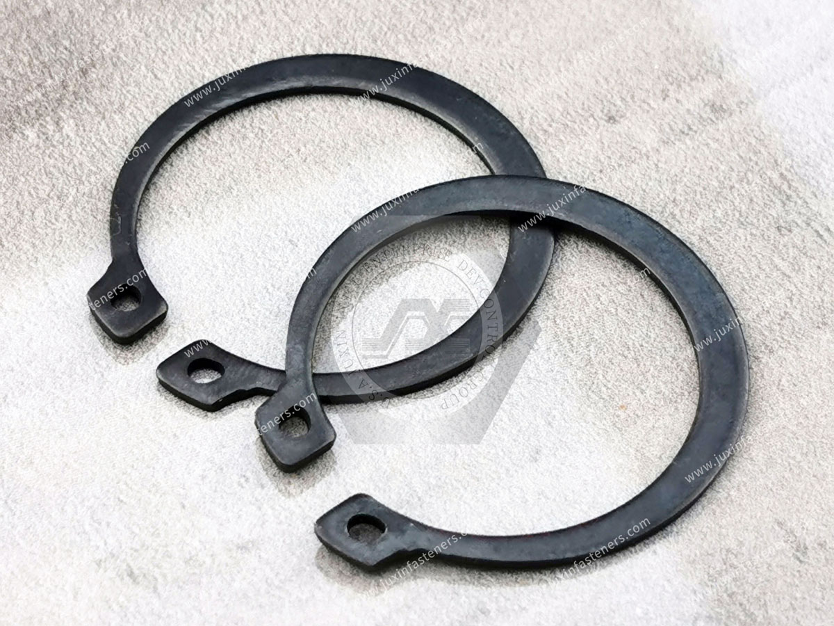
A shaft retaining ring is a mechanical component used to restrict axial movement of another component mounted on a shaft.
Depending on the design, it may also be called:
external retaining ring;
external circlip;
shaft circlip;
external snap ring;
retaining washer;
E-ring.
These terms overlap in commercial usage, but they do not always identify the same geometry.
The basic function is:
Retained Component → Retaining Ring → Shaft Groove → Shaft
The groove is therefore part of the retaining system.
Its primary function is:
Axial Retention
Typical retained components include:
bearings;
gears;
spacers;
sleeves;
pulleys;
sprockets;
rollers;
mechanical subassemblies.
The retaining ring creates a mechanical stop against axial movement.
The old assumption that a retaining ring transfers shaft torque is generally misleading.
Torque between a shaft and rotating component is normally transmitted through an appropriate feature such as:
key;
spline;
interference fit;
clamping hub;
another engineered drive interface.
The retaining ring primarily controls axial movement.
Therefore:
Axial Retention ≠ Torque Transmission
A gear may be axially retained by a circlip while its torque is transmitted by a spline or key.
These are separate functions.
A retaining ring should not automatically be specified to carry the primary radial load of a rotating component.
Radial loads should normally be supported by the intended:
bearing;
shaft;
housing;
structural interface.
Therefore:
Retaining Ring ≠ Radial Bearing
Spring characteristics allow retaining rings to deform during installation and recover into their grooves.
That does not mean they should automatically be described as vibration absorbers.
Therefore:
Elastic Installation Behavior ≠ Vibration Damping
If the assembly requires vibration isolation, damping or rotational anti-loosening, those functions should be addressed separately.
Before choosing a standard, identify where the retaining ring is installed.
The ring is installed on the outside of a shaft.
Examples include:
DIN 471 external retaining rings;
ASME B18.27 external types;
E-rings;
DIN 6799 retaining washers;
shaft snap rings.
The ring is installed inside a housing or bore.
Examples include:
DIN 472 internal retaining rings;
ASME internal retaining rings.
This article focuses on shaft-retention systems.
For internal bore applications, refer to the JUXIN FASTENERS DIN 472 Internal Retaining Rings: Bore Groove, Axial Load & Selection Guide.
The dimensional system is an important early decision.
DIN 471 is a major standard for metric shaft retaining rings.
ASME B18.27 covers tapered and reduced-cross-section retaining rings in inch-series dimensions.
Do not convert an inch shaft diameter into an approximate metric dimension and assume a DIN ring will fit correctly.
Likewise, a metric shaft should not automatically receive an inch-series retaining ring because the nominal diameters appear close.
The groove geometry matters.
DIN 471 covers retaining rings for shafts in:
normal type;
heavy type.
The current edition is:
DIN 471:2026-05
DIN identifies these rings as components used to secure parts such as rolling bearings on shafts and to transmit axial forces.
DIN 471 is therefore a strong starting point when the design uses:
metric shafts;
external shaft grooves;
conventional circlip installation;
DIN-controlled drawings.
DIN 471 includes both normal and heavy configurations.
Do not assume:
Heavy Type = Better for Every Joint
The correct type depends on:
drawing requirement;
axial force;
shaft geometry;
groove;
installation space;
complete assembly.
Changing ring type may also require changing the groove.
For U.S. inch-series equipment, ASME B18.27 is an important standard family.
The current listed standard is:
ASME B18.27-1998 (S2022)
It covers multiple tapered and reduced-cross-section retaining-ring types rather than one universal external ring.
These include conventional external, internal, E-ring, heavy-duty and other specialized geometries.
External Type NA1 is one of the conventional shaft-retaining configurations covered by ASME B18.27.
It is particularly relevant to:
U.S. industrial equipment;
inch shafts;
North American OEM drawings;
legacy machinery;
MRO replacement.
For detailed inch-series selection, refer to the JUXIN FASTENERS ASME B18.27 External Retaining Rings: Inch Shaft & NA1 Selection Guide.
Both standards include external shaft-retention solutions, but they should not be treated as interchangeable systems.
| Selection Factor | DIN 471 | ASME B18.27 |
|---|---|---|
| Primary dimensional system | Metric | Inch |
| Main use on this cluster | External shaft ring | Multiple retaining-ring types |
| Conventional external type | DIN 471 configuration | NA1 |
| Heavy configuration | Included | NA4 among covered types |
| Groove system | DIN metric geometry | ASME inch geometry |
| Typical sourcing context | Metric/global equipment | U.S./inch equipment |
| Automatic interchangeability | No | No |
An E-ring is a retaining component with an E-shaped profile designed for radial installation onto a shaft groove.
Unlike many conventional external circlips, an E-ring does not need to be expanded over the shaft end using conventional circlip pliers.
This can be important in assembly design.
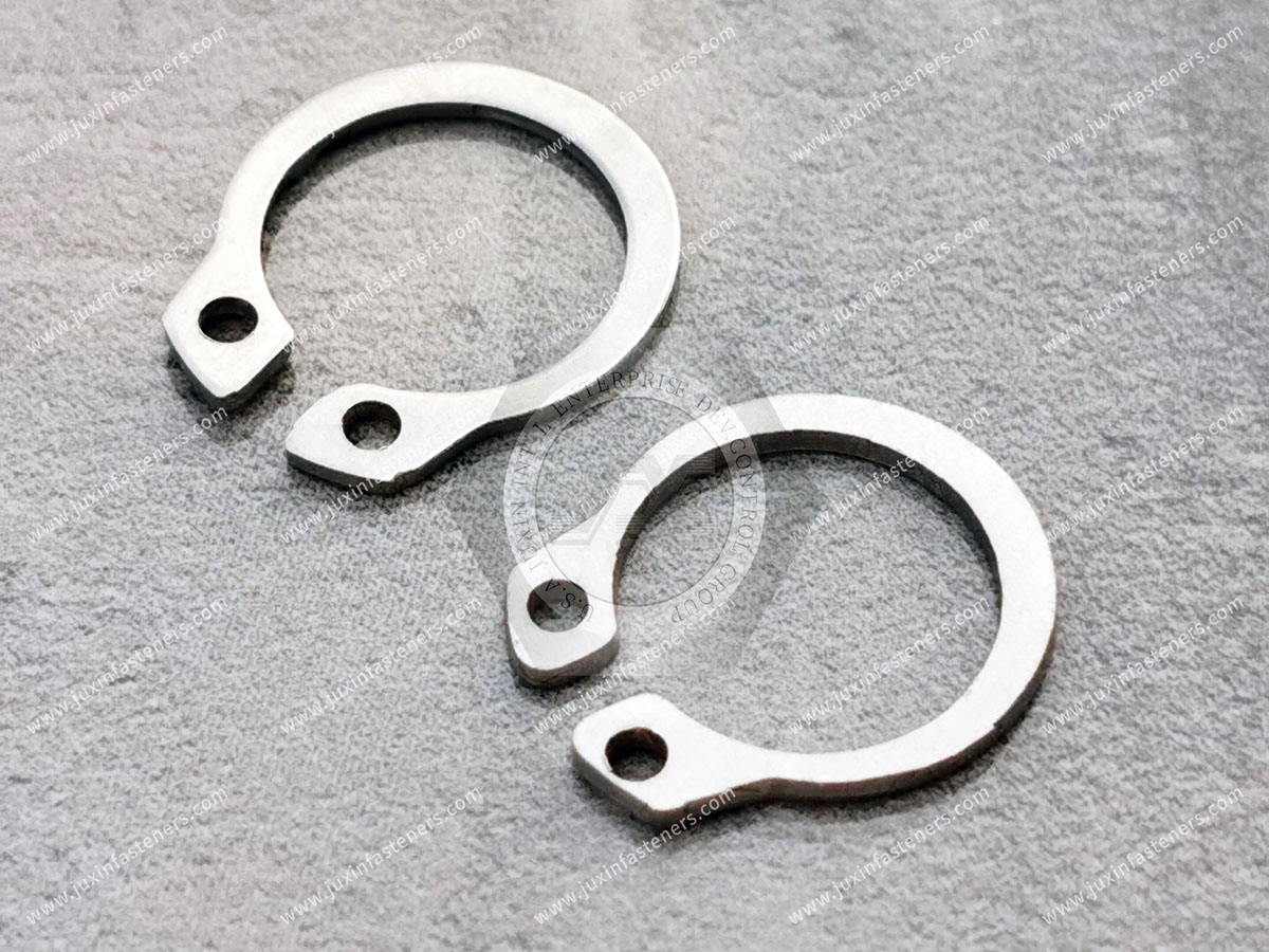
Installation direction is one of the most overlooked retaining-ring selection criteria.
Often installed axially over the end of the shaft before seating in the groove.
Installed radially into the groove from the side.
This creates a useful decision rule:
Shaft End Accessible → Conventional External Ring May Be Practical
Shaft End Not Accessible → Radial-Install Retaining Architecture May Be Worth Evaluating
The actual design and standard must still be checked.
Consider an assembly where the shaft end is blocked by another component.
An axial-install external ring may be difficult or impossible to install.
A radial-install ring can sometimes simplify the assembly sequence.
This means retaining-ring selection is not only about load.
It is also about:
Assembly Architecture
ASME B18.27 includes:
E-Ring Type NA3
and other E-ring-related configurations.
These should not automatically be substituted for NA1 external rings.
The groove and installation architecture must match the selected ring.
Another shaft-retention family is covered by:
DIN 6799
The current DIN catalogue lists:
DIN 6799:2026-05 — Retaining Washers for Shafts
This is a separate product family from DIN 471.
Therefore:
DIN 471 Retaining Ring ≠ DIN 6799 Retaining Washer
They may solve related axial-retention problems but use different geometries.
A retaining washer may provide advantages for particular:
shaft geometry;
groove geometry;
assembly direction;
space constraints.
The correct component should be selected from the drawing or actual design requirement.
Do not substitute solely because both products retain components on shafts.
DIN also maintains standards for round-wire snap rings.
For shaft applications, this includes:
DIN 9925 — Round Wire Snap Rings for Shafts
Round-wire rings differ from conventional stamped retaining rings in:
cross section;
groove interaction;
installation behavior.
Therefore:
Round-Wire Snap Ring ≠ DIN 471 Circlip
Another retaining architecture uses a rectangular profile.
DIN lists:
DIN 9927 — Snap Rings with Rectangular Profile for Shafts
Again, this is a distinct product family.
The cross-section geometry changes how the ring interfaces with the groove and retained component.
There is no single ideal retaining ring for every shaft.
Different designs solve different combinations of:
axial load;
shaft diameter;
available radial space;
available axial space;
assembly access;
groove geometry;
serviceability;
rotational speed;
production method.
This is why selecting by shaft diameter alone is insufficient.
Regardless of retaining-ring type:
Ring + Groove + Shaft = Retention System
The groove determines:
ring engagement;
axial location;
remaining shaft section;
load transfer;
installation behavior.
A high-quality retaining ring installed into an incorrect groove may not perform correctly.
Groove diameter influences:
engagement;
ring position;
remaining shaft cross-section.
A deeper groove is not automatically better.
The applicable standard or validated drawing should control the dimension.
Groove width affects:
axial fit;
seating;
clearance;
load transfer.
Incorrect width can produce either excessive movement or assembly interference.
The groove's axial position determines where the retained component stops.
This can influence:
bearing location;
gear alignment;
end play;
spacer stack;
assembly tolerance.
Axial force is transferred from the component through the retaining ring into the groove.
The groove edge must therefore withstand the resulting load.
Potential failure modes can include:
groove deformation;
local yielding;
shearing;
ring pull-out.
A strong retaining ring cannot compensate for a weak or unsuitable shaft groove.
The complete system should consider:
shaft material;
shaft hardness;
groove geometry;
axial force;
ring geometry.
Therefore:
Higher Ring Strength ≠ Automatically Higher Assembly Capacity
This is one of the most important engineering questions.
Possible axial-force sources include:
bearing thrust;
gear reaction;
spring force;
actuator force;
hydraulic or pneumatic force;
assembly preload;
transient impact.
The retaining system should be evaluated against the actual load case.
In hydraulic and pneumatic equipment, pressure acting on an effective area can generate axial force.
Conceptually:
Axial Force = Pressure × Effective Area
The retaining ring does not have a universal pressure rating independent of the assembly.
Pressure must first be converted into the mechanical load acting on the retained component.
A constant axial load differs from repeated loading.
Applications involving:
reciprocating equipment;
repeated thrust;
load reversal;
impact;
shock
may require additional engineering evaluation.
Some shaft retaining rings rotate with the shaft.
At elevated rotational speed, the design may need to consider:
centrifugal effects;
ring geometry;
balance;
ring mass;
shaft diameter;
surrounding components.
A ring that fits dimensionally is not automatically suitable for unlimited RPM.
Conventional lugged external retaining rings are not perfectly rotationally symmetric.
For many ordinary applications this is not the controlling factor.
For high-speed precision equipment, however, ring geometry and rotating balance may become more important.
Alternative retaining architectures may be considered where appropriate.
Bearings are among the most common components retained by shaft rings.
A typical arrangement is:
Shaft Shoulder → Bearing Inner Ring → External Retaining Ring
The shoulder controls one direction.
The retaining ring controls the other.
A retaining ring can locate a bearing without applying a controlled preload.
If the bearing system requires preload, additional design elements may be required.
Possible components include:
wave spring washers;
disc springs;
precision spacers;
shoulders.
Therefore:
Bearing Location ≠ Bearing Preload
A shaft retaining ring may prevent a gear from moving axially.
But the ring should not automatically be expected to transmit the drive torque.
A typical architecture may be:
Spline / Key → Torque Transfer
Retaining Ring → Axial Retention
Separating these functions improves design clarity.
The same principle applies to:
pulleys;
sprockets;
sheaves.
The retaining ring controls axial movement.
The drive interface should transmit torque.
Retaining rings can also locate:
spacers;
sleeves;
collars;
rollers.
The axial-load requirement may be relatively low or substantial depending on the mechanism.
The component name alone does not determine the required ring.
A retaining ring can fail before entering service if installed incorrectly.
Selection should therefore include:
How will this ring be installed?
Possible methods include:
circlip pliers;
radial insertion;
guide tools;
dedicated production tooling;
automated installation equipment.
A conventional external circlip is generally expanded so it can pass over the shaft.
Once aligned with the groove, it is released.
The ring then contracts into the groove.
The ring only needs enough expansion to clear the shaft.
Excessive expansion can cause:
permanent set;
distortion;
reduced spring recovery;
lug damage;
installation-hole damage.
Therefore:
More Installation Expansion ≠ Easier or Better Installation
After installation, verify that the ring is fully seated.
Potential causes of incomplete seating include:
burrs;
contamination;
incorrect groove;
incorrect ring;
permanent deformation;
poor tooling.
Stamped retaining rings can have edge characteristics resulting from manufacturing.
Whether orientation matters depends on:
ring type;
manufacturing process;
load direction;
drawing;
supplier specification.
There is no single orientation instruction that should be applied blindly to every retaining ring.
The old practice of instructing users to apply lubricant before every installation is too broad.
Lubrication can affect:
handling;
contamination;
assembly process;
corrosion protection;
adjacent components.
Follow the applicable equipment and assembly specification.
Do not introduce lubricant into a controlled assembly unless permitted.
Another common procedural mistake is combining retaining-ring installation with bolt-torque instructions.
A conventional retaining ring is not tightened by torque.
It is seated mechanically in its groove.
If the assembly also contains:
bolts;
shaft nuts;
clamping screws,
those components may have torque requirements.
But those requirements are separate from retaining-ring installation.
The correct groove location is defined by the mechanical design.
The ring may retain:
bearing;
gear;
spacer;
sleeve;
pulley;
another component.
There is no universal rule that a shaft retaining ring should always be positioned near a bearing.
Retaining-ring materials must provide the mechanical behavior required for installation and service.
Selection depends on:
ring standard;
load;
geometry;
corrosion environment;
temperature;
customer drawing.
Avoid assuming one material is universal for every retaining-ring standard.
Spring steel is widely used for retaining components because it can provide suitable elastic behavior.
However:
Spring Steel ≠ Corrosion-Proof
Environmental protection may be required.
Stainless steel can provide improved corrosion resistance for appropriate environments.
Selection should still consider:
required spring properties;
temperature;
chemicals;
mating materials;
load.
Stainless steel should not be described as universally corrosion-proof.
Potential surface treatments depend on:
material;
corrosion environment;
customer specification;
dimensional requirements;
assembly conditions.
Do not specify a coating only because it is common.
Where hardened spring-steel retaining components undergo processes capable of introducing hydrogen, embrittlement risk may require consideration.
Risk depends on factors including:
material condition;
hardness;
manufacturing route;
coating process;
applied stress.
There is no universal bake schedule appropriate for every retaining ring.
Packaging such as:
plastic bags;
oil paper;
protective packaging
can help protect components during storage and transportation.
But packaging should not be confused with the actual surface finish or corrosion-protection specification.
Possible contributors:
excessive axial load;
incorrect groove;
incomplete seating;
wrong ring;
shaft deformation.
Possible contributors:
insufficient shaft strength;
incorrect groove geometry;
excessive axial force;
impact.
Possible contributors:
over-expansion;
wrong installation tool;
overload.
Possible contributors:
burrs;
contamination;
incorrect dimensions;
ring distortion.
Corrosion can reduce effective section or interfere with serviceability.
Incorrect tools can damage:
lugs;
holes;
ring edges;
surface coating.
Generic Type A / Type B terminology can be ambiguous across markets and suppliers.
Instead of purchasing by an informal type name, identify:
applicable standard;
ring geometry;
shaft size;
groove dimensions;
material;
finish.
For global OEM supply chains, this is much safer than relying on regional terminology.
A customer should not have to interpret a local material designation to buy an international retaining ring.
For international sourcing, use:
applicable standard material requirements;
recognized international material designation where specified;
controlled customer drawing.
This reduces ambiguity across suppliers and regions.
A practical engineering decision process is:
If shaft → continue with external retaining architecture.
If bore → evaluate internal retaining rings.
Metric → DIN and other metric systems may be appropriate.
Inch → ASME B18.27 may be relevant.
If yes → conventional external circlip may be practical.
If no → evaluate radial-install designs such as an appropriate E-ring or retaining washer.
Determine the actual mechanical force.
Check:
diameter;
width;
position;
surrounding shaft section.
Verify groove strength.
Consider ring geometry where relevant.
Select material and finish accordingly.
Consider installation and maintenance access.
Confirm fit, seating and retention before production release.
| Retaining System | Typical Use | Installation Direction | Key Selection Issue |
|---|---|---|---|
| DIN 471 | Metric shafts | Axial | Groove + axial load |
| ASME B18.27 NA1 | Inch shafts | Axial | Inch groove + ring type |
| ASME B18.27 NA4 | Heavy-duty inch external application | Axial | Specific heavy-duty geometry |
| E-Ring | Shaft retention | Radial | Side access + matching groove |
| DIN 6799 | Shaft retaining washer | Radial / design-dependent | Matching DIN geometry |
| DIN 9925 | Round-wire shaft snap ring | Design-dependent | Round-wire groove/interface |
| DIN 9927 | Rectangular-profile shaft snap ring | Design-dependent | Profile + groove geometry |
| Custom Ring | Special equipment | Application-specific | Drawing validation |
Consider DIN 471 when:
the shaft is metric;
the drawing specifies DIN 471;
a conventional external circlip architecture is required;
the corresponding groove can be provided.
For detailed selection, see the JUXIN FASTENERS DIN 471 External Retaining Rings: Shaft Groove, Axial Load & Selection Guide.
Consider ASME B18.27 when:
the equipment uses inch dimensions;
the drawing references ASME/ANSI retaining rings;
a North American legacy replacement is required;
the required NA ring type is known.
For detailed sourcing, see the JUXIN FASTENERS ASME B18.27 External Retaining Rings: Inch Shaft & NA1 Selection Guide.
An E-ring may be worth evaluating when:
radial installation is useful;
shaft-end access is limited;
assembly speed is important;
the groove and load match the ring design.
Do not substitute an E-ring into a conventional circlip groove without verifying compatibility.
Alternative designs may be appropriate when the assembly requires:
different installation access;
different groove geometry;
high rotational requirements;
compact radial packaging;
specific OEM architecture.
The decision should be engineering-driven rather than based only on catalogue availability.
Potential shaft-retaining applications include:
electric motors;
pumps;
actuators;
drive systems;
gearboxes;
seat mechanisms;
thermal-management equipment.
Safety-critical automotive applications require customer-specific validation and qualification.
Shaft retaining rings may locate:
bearings;
sleeves;
rotor-related mechanical components;
spacers.
For high-speed motors, rotational requirements should be included in the selection process.
Potential retained components include:
bearings;
gears;
spacers;
sleeves.
Separate:
Axial Retention
from:
Torque Transmission
and:
Bearing Preload
These functions may require different components.
Retaining rings can locate appropriate:
bearings;
sleeves;
internal shaft components.
They should not be treated as fluid seals.
Pressure acting on components can create axial force.
The retaining system should be selected from that mechanical force rather than from system pressure alone.
Applications may include:
actuators;
rollers;
motors;
gear units;
positioning mechanisms;
compact drive systems.
Assembly access can make retaining-ring architecture particularly important.
Potential equipment includes:
pumps;
motors;
fans;
blowers;
liquid-cooling equipment.
Retaining rings may be used within these mechanical systems where their shaft architecture requires axial retention.
The data-center application itself does not determine the ring standard.
Potential applications include:
fans;
blowers;
pumps;
motors;
compressors;
actuators.
The retaining ring provides axial mechanical retention rather than sealing or vibration isolation.
Potential applications include:
motors;
generators;
auxiliary rotating equipment;
mechanical actuators.
Mechanical retention and electrical performance should be evaluated separately.
Shaft retaining rings are common in:
machine tools;
conveyor equipment;
packaging machinery;
production equipment;
material-handling systems;
rotating machinery.
Applications may include:
transmissions;
hydraulic systems;
bearings;
gears;
actuators;
rotating mechanisms.
Shock and cyclic loads may require additional attention.
Shaft retaining rings may be used in appropriate mechanical assemblies.
Safety-critical applications require the relevant customer and industry requirements.
For marine environments, evaluate:
corrosion;
salt exposure;
material compatibility;
surface finish.
Do not assume every standard spring-steel retaining ring is suitable for marine service.
Generic industrial retaining rings should not automatically be represented as aerospace-qualified components.
Drawing-based requirements for appropriate:
tooling;
ground-support equipment;
MRO fixtures;
non-flight-critical equipment
can be evaluated according to customer requirements.
The groove and axial load also matter.
Axial retention and torque transmission are different functions.
It should not replace the bearing system.
Elastic installation does not make it a damping device.
DIN and ASME geometries should not be mixed casually.
Axial and radial installation can drive product selection.
The groove is part of the load path.
Installation damage can permanently alter geometry.
Follow the controlled assembly requirement.
A retaining ring is seated, not torqued.
Use the actual standard and geometry.
The complete shaft and groove must match.
Engineers may search:
shaft retaining ring;
retaining ring types;
external circlip;
external snap ring;
shaft circlip;
DIN 471 vs E-ring;
DIN 471 vs ASME retaining ring;
E-ring vs circlip;
retaining ring for bearing;
shaft retaining ring groove;
retaining ring axial load;
retaining ring for high speed shaft;
snap ring selection;
external retaining ring selection.
These queries represent real engineering selection tasks.
Procurement teams may search:
shaft retaining ring supplier;
external circlip manufacturer;
retaining ring manufacturer;
DIN 471 supplier;
ASME retaining ring supplier;
E-ring supplier;
snap ring manufacturer;
stainless retaining ring supplier;
spring steel retaining ring supplier;
custom retaining ring manufacturer;
OEM retaining ring supplier.
These queries carry stronger commercial intent.
For technical and commercial evaluation by JUXIN FASTENERS, provide where applicable:
application;
retained component;
standard;
ring type;
nominal shaft size;
metric or inch system;
customer part number;
drawing;
shaft drawing;
groove diameter;
groove width;
groove location;
shaft material;
shaft hardness where relevant;
expected axial load;
static or cyclic loading;
shock or impact requirement;
rotational speed;
operating temperature;
corrosion environment;
ring material;
surface finish;
installation direction;
installation method;
removal requirement;
dimensional tolerances;
inspection requirement;
documentation requirement;
sample quantity;
prototype quantity;
production quantity;
estimated annual demand;
packaging requirement;
labeling requirement;
customer-specific requirements.
It is a mechanical retaining component used to restrict axial movement of another component mounted on a shaft.
Common terms include external retaining ring, external circlip, shaft circlip and external snap ring, although exact geometries can differ.
Its primary function is axial retention. Drive torque should normally be transferred by the intended key, spline, interference fit or other drive feature.
It should not be treated as a dedicated vibration-damping component.
DIN 471 is the DIN standard for retaining rings for shafts in normal and heavy types.
DIN 471:2026-05 is the current edition.
ASME B18.27 covers tapered and reduced-cross-section retaining rings in inch-series dimensions.
DIN 471 is primarily a metric shaft-retaining-ring standard. ASME B18.27 covers multiple inch-series retaining-ring types. Their rings and grooves should not be assumed interchangeable.
An E-ring is a shaft-retention component with an E-shaped geometry that is typically installed radially into a matching groove.
Radial installation can be useful where shaft-end access is restricted or the assembly architecture favors side installation.
DIN 6799 covers retaining washers for shafts. It is a separate product family from DIN 471 retaining rings.
No. Round-wire snap rings use a different cross section and corresponding groove/interface geometry.
Not based on approximate diameter conversion alone. Verify the standard, groove dimensions, tolerances and load requirements.
Reuse should follow the OEM or equipment maintenance requirement and should not automatically be assumed.
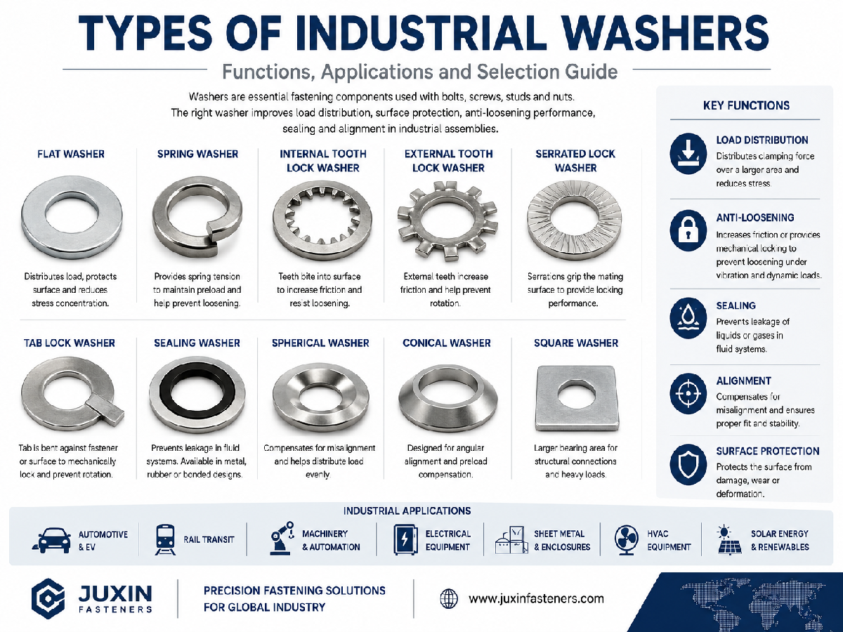
JUXIN FASTENERS can evaluate standard and drawing-based shaft-retaining requirements based on standard,
ring geometry, shaft size, groove, material, finish, operating conditions and production quantity.
A buyer may initially request:
“Shaft retaining ring, 20 mm, 100,000 pcs.”
That is not yet a complete production specification.
The next questions are:
DIN 471, ASME B18.27, E-Ring or Another Type?
Metric or Inch?
What Is the Groove Diameter?
What Is the Groove Width?
What Is Being Retained?
What Axial Load Must Be Transferred?
Is Axial Installation Possible?
What RPM Applies?
What Is the Shaft Material?
What Ring Material and Finish Are Required?
The commercial path becomes:
Application → Shaft → Axial Load → Installation Access → Groove → Standard → Ring Type → Material / Finish → Validation → Production RFQ
That is the difference between buying a ring that merely fits the shaft and sourcing a retaining system that matches the actual mechanical design.
JUXIN FASTENERS supports OEM sourcing of:
shaft retaining rings;
external retaining rings;
external circlips;
DIN 471 retaining rings;
ASME B18.27 retaining rings;
E-rings;
retaining washers;
snap rings;
spring-steel retaining rings;
stainless steel retaining rings;
drawing-based retaining components.
Potential application sectors include:
industrial machinery;
automotive and EV equipment;
electric motors;
gearboxes;
pumps and compressors;
industrial automation;
robotics;
HVAC and liquid-cooling equipment;
AI data center and HPC equipment;
power equipment;
construction machinery;
agricultural machinery;
rail-related equipment;
marine equipment;
MRO and legacy machinery.
For metric external shaft-retaining rings, refer to the JUXIN FASTENERS DIN 471 External Retaining Rings: Shaft Groove, Axial Load & Selection Guide.
For U.S. inch-series retaining rings, refer to the JUXIN FASTENERS ASME B18.27 External Retaining Rings: Inch Shaft & NA1 Selection Guide.
For internal bore-retaining systems, refer to the JUXIN FASTENERS DIN 472 Internal Retaining Rings: Bore Groove, Axial Load & Selection Guide.
For bearing preload rather than axial retention, refer to the JUXIN FASTENERS Bearing Preload Wave Washers: Load, Working Height, Tolerance Stack & Selection Guide.
For custom machined shaft and groove components, see Stainless Steel CNC Machining Parts.
For OEM shaft retaining ring RFQs, send your drawing, standard, shaft size, groove dimensions, retained component, axial load, rotational speed where relevant,
material, finish, quantity and estimated annual demand to:
The best shaft retaining ring is not simply:
“the strongest ring that fits the shaft.”
It is:
“the retaining architecture whose standard, groove, axial capacity, installation method and material match the actual mechanical system.”
 MORE NEWS

Sep. 27, 2026

Sep. 27, 2026

Sep. 27, 2026
Contact Us
Tel.:
+86 020 8621 0320
+86 020 3121 6067
E-mail:
Technical Support:
Navigation
SEND INQUIREY