
Call Us
+86 136 6007 9809
Call Us
+86 136 6007 9809

Oct. 12, 2023
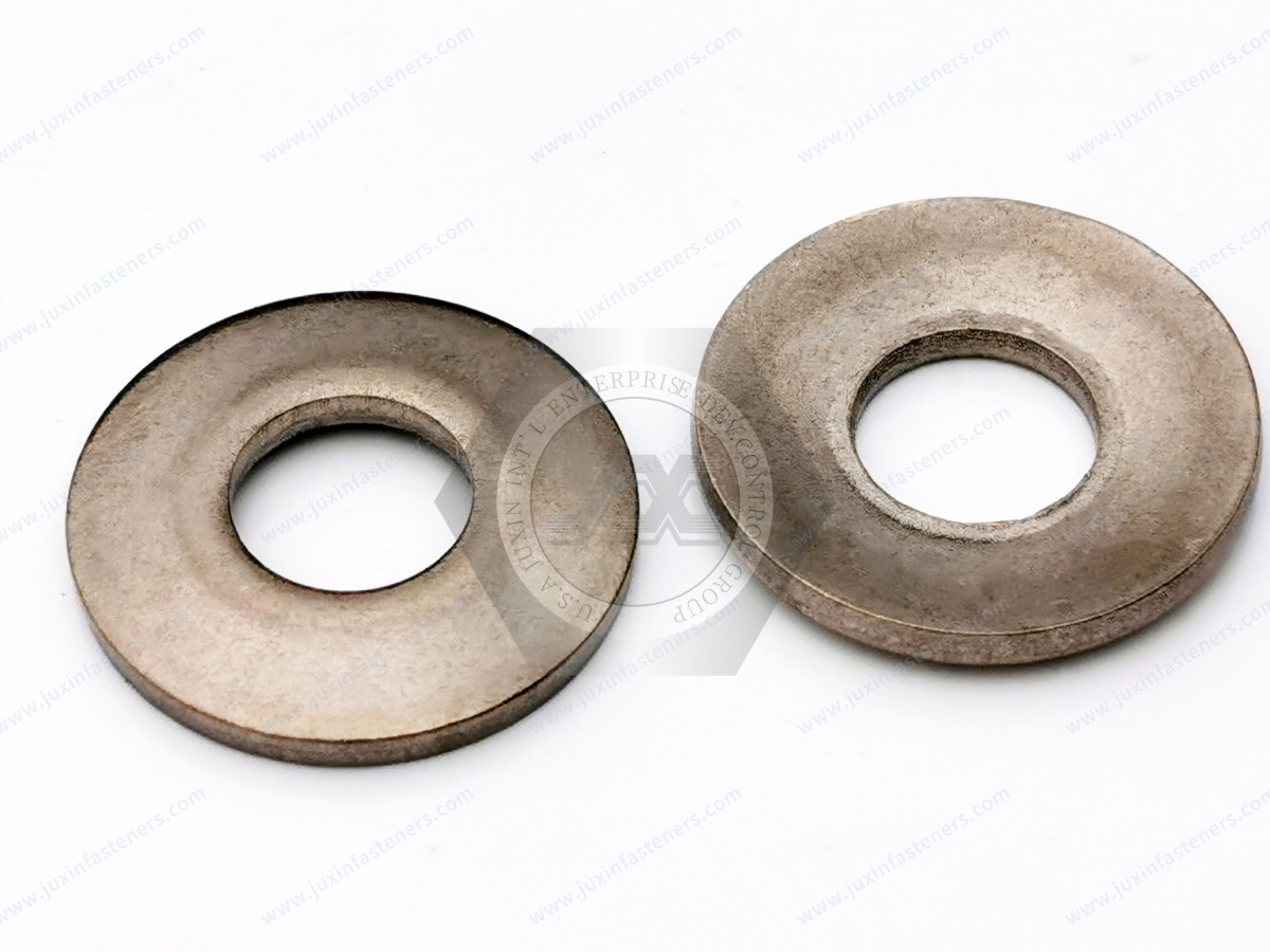
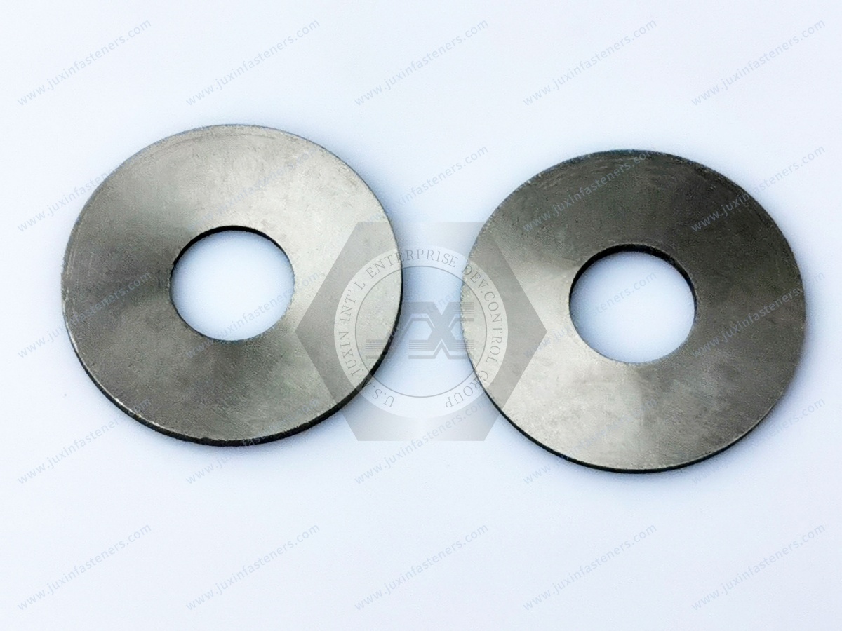
Disc springs, also known as Belleville springs or Belleville washers, are compact conical spring elements used when an assembly requires substantial axial force within limited installation space.
Their real engineering value, however, goes beyond compact size.
A disc spring can be selected or combined into a stack to create a controlled relationship among:
preload;
axial force;
working deflection;
available travel;
installed height;
stiffness;
fatigue duty;
and available installation space.
This makes disc springs useful in machinery, actuators, bearing systems, valves, clamping mechanisms, power equipment,
industrial automation and other assemblies where force must be maintained or controlled as components move.
For engineering selection, the most useful starting point is not:
“What diameter Belleville washer do I need?”
It is:
“What force is required, at what position, through what travel, inside what installation envelope, and for how many cycles?”
That change in question is the foundation of reliable disc spring design.
A disc spring is an annular conical spring that elastically deflects under axial loading.
Its fundamental geometry includes:
outside diameter;
inside diameter;
thickness;
free height;
and cone height.
But geometry alone does not fully define its application.
Engineers must also consider:
spring force;
deflection;
working position;
stress;
material;
fatigue duty;
relaxation;
temperature;
surface condition;
guidance;
and whether the spring operates individually or in a stack.
Current European disc-spring engineering is covered by EN 16983 for quality specifications and dimensions and EN 16984 for calculation.
Older drawings may still reference DIN 2093. That designation should be treated as a legacy requirement and reviewed against the applicable project specification rather than presented as the current disc-spring standard.
Before selecting dimensions, answer four questions.
Define the required axial force at the relevant operating condition.
Do not simply state:
“High preload required.”
Where possible, define:
initial force;
working force;
maximum force;
and allowable force variation.
Define how far the spring must move between operating positions.
This may include:
assembly compression;
working movement;
compensation travel;
and maximum permitted deflection.
Specify:
maximum outside diameter;
minimum bore or guide diameter;
available axial height;
surrounding component clearance;
and assembly-access limitations.
A static preload application and a dynamically cycled application should not be evaluated in the same way.
Define:
static or dynamic duty;
expected number of cycles;
movement per cycle;
temperature;
and environmental conditions.
This gives a practical design model:
Force + Travel + Envelope + Life → Disc Spring Architecture
Preload means the disc spring is intentionally compressed from its free position before or during assembly so that it already produces a defined force at the installed condition.
This can be useful when an assembly needs:
initial clamping force;
contact force;
bearing preload;
actuator return force;
compensation for dimensional movement;
or another controlled axial force.
Preload should therefore be treated as an operating point on the spring's force–deflection behavior.
It is not simply “tightening the disc spring.”
A useful disc-spring design should distinguish among several conditions.
The spring is unloaded.
The spring has been compressed during assembly and generates the required initial preload.
The spring moves through the normal operating range of the equipment.
The spring reaches the maximum intended deflection permitted by the design.
These positions should be defined before sourcing.
A supplier cannot reliably select a spring if the RFQ provides only:
OD × ID × Thickness
but no force or working-position requirement.
Disc springs are sometimes installed in bolted assemblies.
This can create confusion between:
disc-spring force;
bolt preload;
and complete joint clamp force.
These are related only through the actual assembly architecture.
Therefore:
Disc Spring Force ≠ Automatically Bolt Preload
and
Disc Spring Preload ≠ Automatically Anti-Loosening
If the actual requirement concerns a DIN 6796 conical spring washer in a bolted joint, that is a different selection problem from designing a mechanical disc-spring system.
A major reason engineers use disc springs is their ability to generate substantial axial force in relatively limited axial space.
This can be valuable where a conventional helical spring would require more installation length.
Potential applications include:
bearing preload;
valve mechanisms;
clamping systems;
actuator mechanisms;
overload protection;
brake and clutch mechanisms;
tooling;
fixture systems;
and compact industrial machinery.
But “compact” does not mean universally superior.
The correct spring architecture depends on force, travel, fatigue, guidance, friction and packaging.
The simplest configuration is one disc spring.
A single spring may be appropriate when one component already provides the required:
force;
travel;
installation height;
and life.
Advantages can include:
fewer components;
simpler guidance;
fewer friction interfaces;
easier inspection;
and simpler assembly.
If one disc spring meets the requirement, additional stacking should not be added without an engineering reason.
A single disc spring may not provide the required combination of force and travel.
Stacking allows engineers to modify the behavior of the spring system.
The three fundamental arrangements are:
Series
Parallel
Series–Parallel Combination
The arrangement matters because changing the stack changes the system response.
In a series stack, disc springs are arranged in alternating orientation.
Conceptually, each spring contributes deflection.
For similar springs:
Series Arrangement → Increased Total Travel
while the force required to deflect each spring remains associated with the individual spring behavior, subject to real stack effects.
This makes series stacking useful when the design needs more axial movement than one spring can provide.
Potential reasons include:
increased compensation travel;
longer working stroke;
accommodation of dimensional movement;
packaging a required force over a larger displacement;
and adjusting system stiffness.
However, simply adding more discs is not automatically better.
A longer stack introduces additional considerations involving:
guidance;
alignment;
friction;
tolerance accumulation;
and stability.
Parallel stacking generally means nesting multiple disc springs in the same orientation.
Conceptually:
Parallel Arrangement → Increased Combined Force
while available deflection remains related to the behavior of the nested group.
Parallel stacking may be useful where one disc spring cannot provide the required force within the available radial envelope.
Nested disc springs contact each other.
That contact creates friction.
As the stack compresses and releases, friction can affect:
measured force;
hysteresis;
loading and unloading behavior;
heat generation;
surface wear;
and repeatability.
Therefore:
Ideal Mathematical Stack ≠ Automatically Actual Physical Stack
For precision applications, friction should be considered rather than ignored.
Some applications require both:
greater force than one disc can provide;
and greater travel than one disc can provide.
Series and parallel groups can then be combined.
Conceptually:
Parallel Groups → Increase Force
Series Groups → Increase Travel
A combined stack allows the designer to balance:
force;
travel;
installed height;
stiffness;
and packaging.
However, the number of interfaces and components also increases.
That makes tolerance, guidance and friction progressively more important.
Statements such as:
“Use four washers for more force”
or
“Use six washers for more travel”
are incomplete.
The actual design depends on:
individual disc geometry;
arrangement;
spring force;
required deflection;
friction;
tolerances;
guidance;
stress;
and operating conditions.
The stack configuration should follow the required force–deflection behavior.
A disc spring does not have to behave like a conventional linear coil spring.
Its force–deflection curve depends strongly on geometry.
This is one of the reasons disc springs can be useful in specialized mechanical systems.
But descriptions such as:
linear;
progressive;
regressive;
nearly constant force;
or unusual stiffness behavior
should not be assigned to an unspecified washer simply because it is conical.
The actual curve should come from the applicable geometry, calculation and validated product data.
Thickness strongly influences disc-spring behavior, but it does not operate independently.
Changing thickness while keeping other dimensions constant also changes:
stress;
geometry ratios;
spring force;
deflection behavior;
fatigue conditions;
and manufacturing feasibility.
Likewise, saying:
“Thin washer = more travel”
is not a sufficient design rule.
Disc spring selection must consider the entire geometry.
A disc spring stack can produce different force values during compression and release.
One contributor is friction between contacting surfaces.
This difference is commonly observed as hysteresis.
Depending on the application, hysteresis may be:
acceptable;
undesirable;
or part of the system behavior that must be quantified.
For a precision preload mechanism, repeatability may be more important than energy dissipation.
For another mechanism, some frictional energy dissipation may be acceptable.
Therefore, it is better to specify the required system behavior than to market all stacked disc springs generically as “vibration dampers.”
Lubrication may be used in some disc-spring assemblies to influence:
friction;
wear;
corrosion;
and stack behavior.
However, no single lubricant should be recommended universally.
Selection depends on:
material;
surface treatment;
temperature;
surrounding components;
contamination requirements;
service interval;
and operating environment.
In semiconductor, food-service, medical or other contamination-sensitive equipment, lubricant selection may require additional restrictions.
A long or multi-disc stack may require guidance to maintain alignment.
Depending on the assembly, guidance may be provided by:
an internal guide;
an external guide;
a shaft;
a sleeve;
or surrounding component geometry.
The guide must allow the springs to move without unintended interference.
This creates an important sourcing issue:
Guide Clearance Is Part of the Spring-System Design
It should not be determined only after the springs arrive.
A guide can contact the disc spring during operation.
Engineers should consider:
guide material;
surface finish;
clearance;
lubrication;
wear;
contamination;
and misalignment.
Too little clearance can create binding.
Too much clearance can reduce positional control.
There is no universal guide clearance suitable for every disc spring stack.
A stack contains multiple manufactured components.
Each component has dimensional and force tolerances.
As the number of discs increases, variation can influence:
total stack height;
preload;
force at working position;
travel;
and assembly fit.
This matters particularly when the application has a narrow allowable force window.
Procurement should therefore not evaluate only individual-disc dimensional tolerance.
The assembled stack requirement may also need validation.
Two disc springs with the same nominal dimensions are not necessarily functionally identical if their force characteristics differ.
For replacement sourcing, critical information may include:
force at defined deflection;
allowable force tolerance;
working range;
free height;
material;
and fatigue requirement.
This is one reason a physical dimensional match alone may not establish functional equivalence.
A dynamically cycled disc spring repeatedly moves between load positions.
Fatigue evaluation should therefore consider:
minimum deflection;
maximum deflection;
stress range;
material;
surface condition;
manufacturing quality;
temperature;
corrosion;
and required cycles.
A spring operating statically at preload is not equivalent to a spring cycling continuously through substantial travel.
For dynamic applications, provide the actual operating cycle.
A disc spring held under load for long periods may experience changes in force.
Relaxation depends on factors including:
stress;
material;
temperature;
time;
heat treatment;
and operating condition.
This matters in applications where preload must remain within a defined range over long service periods.
The current EN 16983 framework includes requirements concerning permissible relaxation and fatigue behavior for disc springs.
Temperature can influence:
elastic modulus;
relaxation;
oxidation;
corrosion;
coating;
lubricant;
and long-term spring behavior.
Therefore, generic statements such as:
“This disc spring works to 600°C”
should not be made from material name alone.
High-temperature applications should define:
normal temperature;
peak temperature;
exposure duration;
load;
required force retention;
environment;
and cycle requirement.
Material selection depends on the required combination of:
mechanical properties;
fatigue behavior;
relaxation;
corrosion;
temperature;
manufacturability;
and cost.
Potential material families can include appropriate:
spring steels;
stainless steels;
nickel-based alloys;
and other engineered spring materials.
For demanding applications, materials such as Inconel 718 may be considered where their properties are justified by the actual operating environment.
The material should not be selected solely because it sounds “high performance.”
Surface treatment can influence:
corrosion resistance;
friction;
fatigue;
dimensions;
wear;
and interaction between stacked discs.
Depending on material and application, possible strategies may include appropriate:
phosphate/oil systems;
trivalent zinc systems;
zinc-nickel;
non-electrolytic coatings;
and passivation for suitable stainless materials.
Hexavalent chromium should not be specified.
Finish selection should consider the complete operating environment.
For high-strength or hardened spring components, hydrogen embrittlement can become relevant depending on:
material strength;
hardness;
manufacturing process;
cleaning;
electroplating;
applied stress;
and service condition.
There is no universal post-plating baking recipe suitable for every disc spring.
Where risk exists, the material, process and customer requirements should control the mitigation plan.
Bearing systems are a classic application for controlled axial spring force.
Disc springs may help maintain preload as the assembly experiences:
dimensional variation;
thermal movement;
wear;
or operating displacement.
However, the correct spring force depends on the bearing arrangement.
Too little preload may not achieve the required function.
Too much preload can increase:
friction;
heat;
wear;
and bearing stress.
The disc spring should therefore be selected as part of the bearing system, not independently.
Valves and actuators may require compact spring systems for:
return force;
preload;
closing force;
compensation;
and controlled mechanical movement.
Disc springs can be useful where high axial force is needed within restricted space.
Relevant RFQ information may include:
force at installed position;
working stroke;
maximum stroke;
operating cycles;
temperature;
fluid environment;
and corrosion conditions.
A generic spring dimension is not enough.
Industrial machinery may use disc springs in:
clamping systems;
tool holders;
bearing assemblies;
overload protection;
drive systems;
brake mechanisms;
fixture systems;
and actuator assemblies.
These applications often require different force and life characteristics even when the spring dimensions appear similar.
Machine tools may use disc springs where compact and repeatable axial force is required.
Potential applications include:
spindle systems;
tool-clamping mechanisms;
fixture systems;
braking systems;
bearing preload;
and mechanical actuators.
For precision machinery, force repeatability, hysteresis, wear and fatigue may be more important than maximum theoretical load.
Robotics and automated equipment may use disc springs in:
grippers;
end-of-arm tooling;
fixtures;
clamping mechanisms;
overload protection;
actuators;
and controlled compliance systems.
Relevant engineering questions include:
required force;
working travel;
cycle frequency;
positioning repeatability;
mass;
and maintenance interval.
Dynamic applications should be evaluated for fatigue rather than selected only by static load.
Disc springs may be used in suitable automotive and EV-related:
mechanical actuators;
clamping mechanisms;
bearing systems;
production tooling;
braking or clutch mechanisms where applicable;
manufacturing equipment;
and powertrain-related mechanical systems.
Generic disc springs should not automatically be represented as automotive-qualified or suitable for safety-critical vehicle functions.
Program-specific requirements remain separate.
Disc springs may have suitable applications in:
mechanical clamping systems;
service equipment;
production fixtures;
power equipment;
cooling equipment;
and selected preload mechanisms.
A disc spring should not automatically be treated as:
a battery-cell compression solution;
structural battery fastener;
electrical-contact component;
or safety device
without application-specific engineering.
Electrical equipment may contain mechanical systems requiring controlled preload or movement.
Potential applications include:
switch mechanisms;
mechanical actuators;
heavy electrical machinery;
power equipment;
equipment drives;
and service mechanisms.
Disc springs do not automatically provide electrical bonding or grounding.
Disc springs should not be marketed as generic “AI server fasteners.”
Their credible applications are in equipment where a real mechanical spring function exists.
Potential examples include:
UPS equipment;
PDU equipment;
power-conversion equipment;
cooling systems;
pumps;
valves;
actuators;
CDU equipment;
and mechanical service systems.
The correct search relationship is:
Equipment Function → Required Spring Force → Disc Spring Selection
not simply:
AI Data Center → Disc Spring
Liquid-cooling infrastructure can contain:
pumps;
valves;
actuators;
heat-exchange equipment;
mechanical frames;
and serviceable mechanisms.
Disc springs may be appropriate in selected valve, actuator, preload or mechanical-control functions.
They should not automatically be described as sealing components or pressure-rated hardware.
Semiconductor equipment can use compact spring elements in:
precision mechanisms;
automation;
valves;
fixtures;
clamping systems;
and equipment actuators.
Applications may require special attention to:
particles;
lubricant;
surface treatment;
corrosion;
vacuum compatibility;
and cleanliness.
Standard industrial disc springs should not automatically be described as cleanroom- or vacuum-qualified.
Rail equipment may contain disc springs in suitable:
braking mechanisms;
actuator systems;
mechanical equipment;
preload systems;
and maintenance equipment.
Rail-specific fatigue, vibration, fire and safety requirements remain separate qualification issues.
HVAC and refrigeration systems contain:
compressors;
pumps;
valves;
actuators;
drives;
and mechanical control systems.
Disc springs may be useful where compact preload or return force is required.
Material, temperature, corrosion and cycle requirements should be defined for the actual application.
Commercial food-service equipment includes mechanical systems such as:
refrigeration equipment;
pumps;
dispensing mechanisms;
valves;
door and latch mechanisms;
adjustment systems;
actuators;
and production or service machinery.
Disc springs may provide compact preload or return force in suitable non-food-contact mechanical mechanisms.
However, food-service applications may introduce:
moisture;
cleaning chemicals;
temperature cycling;
grease;
condensation;
and washdown exposure.
Material, coating and lubricant should therefore be selected for the actual environment.
A standard disc spring should not automatically be described as food-contact compliant, hygienic-design certified, washdown-rated or cleaning-chemical resistant.
Potential applications can include:
diagnostic machinery;
laboratory equipment;
mechanical actuators;
adjustment mechanisms;
equipment clamps;
and service mechanisms.
Medical equipment applications may impose special requirements involving:
cleaning;
corrosion;
contamination;
noise;
and precision.
A disc spring itself does not establish medical-device certification, biocompatibility, sterilization compatibility or cleanroom qualification.
Heavy equipment may use disc springs in:
brake systems;
clamping mechanisms;
overload systems;
actuators;
mechanical drives;
and equipment assemblies.
Shock, contamination, corrosion and dynamic loading should be considered.
Generic disc springs should not automatically be represented as structural-building components.
Disc springs may be considered in suitable:
tooling;
ground-support equipment;
test equipment;
fixtures;
mechanical actuators;
and non-flight-critical assemblies
where program requirements permit.
Generic industrial disc springs should not be represented as flight-qualified without the applicable qualification evidence.
Disc springs and helical coil springs solve overlapping but not identical problems.
A disc spring can be attractive when the application requires:
high axial force;
compact axial installation;
stackable architecture;
or specialized force–deflection behavior.
A coil spring may be preferable when the application requires:
longer travel;
a different packaging envelope;
different guidance;
or another spring characteristic.
The correct choice depends on the required system behavior.
There is no universally superior spring type.
These products should not be confused.
A true disc spring is designed as a mechanical spring element.
DIN 6796 addresses conical spring washers for bolted connections.
If the application question is:
“What force do I need at what deflection?”
the project is likely in disc-spring territory.
If the question is:
“What elastic washer should be used in this bolted connection?”
DIN 6796 may be the more relevant product family.
OD and ID do not define spring performance.
The free spring condition is not the operating condition.
Additional discs also add height, friction, tolerances and interfaces.
Parallel and combined stacks can exhibit hysteresis.
Long stacks can require controlled alignment.
Cycle range matters.
Temperature performance depends on the complete material and stress condition.
A mechanical spring and a thread-locking solution are not automatically the same thing.
Same dimensions do not guarantee the same force–deflection behavior.
Individual variation can influence assembled stack performance.
For second-source projects, JUXIN FASTENERS distinguishes among several sourcing objectives.
Critical dimensions and interfaces match the approved requirement.
The spring may contain non-critical differences while providing the required:
installation;
force;
deflection;
material behavior;
and assembly function
after customer validation.
One or more parameters are intentionally changed.
Examples may include:
material;
finish;
free height;
thickness;
or stack arrangement.
A new spring is developed around the actual:
Force + Travel + Envelope + Life
requirement.
For disc springs:
Same Geometry ≠ Automatically Same Function
When the original drawing is unavailable, a physical sample can support development.
A practical workflow is:
Physical Sample → Dimensional Review → Functional Review → Critical Feature Identification → Available Material / Finish Information Review → Force Requirement Confirmation → Drawing Confirmation → Manufacturing Feasibility → Prototype / Sample Development → Customer Validation → Production
A physical sample can help establish:
outside diameter;
inside diameter;
thickness;
free height;
shape;
visible finish;
and stack orientation.
But the sample alone may not reveal:
exact alloy chemistry;
heat treatment;
original spring-force requirement;
fatigue requirement;
relaxation requirement;
original coating chemistry;
or intended working deflection.
That information should come from the drawing, application or customer engineering requirement where available.
Disc spring sourcing contains two distinct search journeys.
Engineers may search:
disc spring preload;
Belleville spring preload;
disc spring stack calculation;
Belleville washer stack arrangement;
disc springs in series;
disc springs in parallel;
disc spring force deflection;
disc spring fatigue life;
disc spring hysteresis;
disc spring relaxation.
Their main question is:
How do I achieve the required force and travel reliably?
Procurement teams may search:
disc spring manufacturer;
Belleville spring supplier;
custom disc springs;
disc spring stack supplier;
disc spring second source;
disc spring from drawing;
Belleville washer manufacturer;
custom spring washer manufacturer.
Their main question is:
Can another supplier reproduce the required geometry and spring performance reliably?
A technically useful RFQ must connect these two search journeys.
For efficient engineering review and quotation, provide as much of the following information as possible.
outside diameter;
inside diameter;
thickness;
free height;
cone height where controlled;
dimensional tolerances;
available installation envelope.
required force at installed position;
required force at working position;
working deflection;
maximum deflection;
acceptable force tolerance;
required travel.
single disc or stack;
number of discs;
series arrangement;
parallel arrangement;
combined arrangement;
free stack height;
installed stack height;
guidance method.
static or dynamic;
minimum working position;
maximum working position;
expected cycles;
operating frequency where relevant;
required service life.
operating temperature;
peak temperature;
corrosion exposure;
chemicals;
humidity;
lubricant restrictions;
contamination restrictions.
material requirement;
heat-treatment requirement where specified;
surface finish;
corrosion requirement;
restricted-substance requirement.
sample quantity;
pilot quantity;
production quantity;
estimated annual usage;
packaging;
traceability requirements where specified;
target schedule;
and long-term supply requirement.
For a second-source disc spring, procurement teams should compare more than dimensional drawings.
Review:
critical dimensions;
force at defined deflection;
force tolerance;
material;
heat treatment where controlled;
hardness where applicable;
surface condition;
finish;
free height;
working range;
fatigue requirement;
relaxation requirement;
stack behavior;
and assembly interface.
A dimensional copy that produces the wrong spring force is not a functional equivalent.
A disc-spring supplier should be evaluated for capabilities relevant to the actual program, which may include:
engineering drawing review;
manufacturing feasibility;
material control;
heat-treatment control where applicable;
dimensional inspection;
force-related inspection where specified;
surface-finish control;
prototype/sample development;
high-volume manufacturing capability;
packaging;
change communication;
and long-term supply support.
For suitable high-volume products, automatic optical sorting may be used for compatible externally measurable characteristics where applicable.
Optical sorting does not replace force–deflection, fatigue, relaxation or complete assembly validation.
JUXIN FASTENERS supports OEM and custom fastener and spring-component projects for industrial manufacturers, engineering teams, procurement organizations and global supply chains.
Disc spring projects can be reviewed from:
customer 2D drawings;
3D information where applicable;
physical samples;
required dimensions;
force and deflection requirements;
material;
surface finish;
stack configuration;
application information;
and production quantities.
For an existing part, the first objective is to understand whether the sourcing requirement is:
an exact dimensional replacement;
a functional equivalent;
a modified alternative;
or a custom redesign.
For a new application, a more useful starting point is:
Required Force → Required Travel → Available Envelope → Required Life → Environment → Material / Finish → Stack Architecture
Prototype or sample evaluation can then be used before volume production so the customer can verify fit, spring behavior and assembly performance in the real equipment.
A practical decision path is:
What mechanical function must the spring perform?
→ What force is required?
→ At what installed position?
→ What working travel is required?
→ What is the maximum allowable outside diameter?
→ How much axial space is available?
→ Can one disc meet the requirement?
→ If not, is more force, more travel, or both required?
→ Series, parallel or combined stack?
→ How will the stack be guided?
→ How will friction and hysteresis affect the mechanism?
→ Is the duty static or cyclic?
→ What fatigue life is required?
→ What temperature and environment apply?
→ What material and finish are required?
→ Is the project an exact replacement, functional equivalent or new design?
→ How will samples be validated?
→ What production volume and long-term supply requirements apply?
This changes the sourcing question from:
“Can you quote this Belleville washer size?”
to:
“Can this disc spring or disc spring stack deliver the required force and travel within the available space throughout the required operating duty?”
That is the question mechanical engineers, design engineers, procurement managers and supplier-development teams should answer before production sourcing.
For disc springs, Belleville springs, disc spring stacks, custom spring components, drawing-based parts, physical-sample development or second-source projects,
send your available drawing, sample, force/deflection requirements, material, finish, application and quantity to:
JUXIN FASTENERS can review the available information and evaluate an appropriate sample-development and manufacturing path for your application.
Previous: Clamp-Style Shaft Collars
 MORE NEWS

Sep. 27, 2026

Sep. 27, 2026

Sep. 27, 2026
Contact Us
Tel.:
+86 020 8621 0320
+86 020 3121 6067
E-mail:
Technical Support:
Navigation
SEND INQUIREY