
Call Us
+86 136 6007 9809
Call Us
+86 136 6007 9809

Sep. 10, 2023
Disc springs are compact conical spring components designed to generate a controlled axial force as they deflect under load.
They are commonly referred to as:
disc springs;
Belleville springs;
Belleville washers;
conical disc springs.
However, engineers and procurement teams should be careful with terminology.
A precision disc spring designed around a defined force-deflection characteristic is not necessarily the same product as a conical spring washer for a bolted connection,
such as a washer specified according to DIN 6796.
The two products can look similar while solving different engineering tasks.
That distinction is critical when selecting, specifying or sourcing these components.
A better engineering selection path is:
Required Force → Required Deflection → Installation Space → Static or Dynamic Load → Single Disc or Stack
→ Stack Configuration → Material → Environment → Fatigue Requirement → Standard or Drawing → Validation
JUXIN FASTENERS supports OEM sourcing of industrial washers, spring components, bolts, nuts, screws and custom fastening components for machinery,
automotive equipment, power systems, industrial automation, HVAC, heavy equipment and other engineered assemblies.
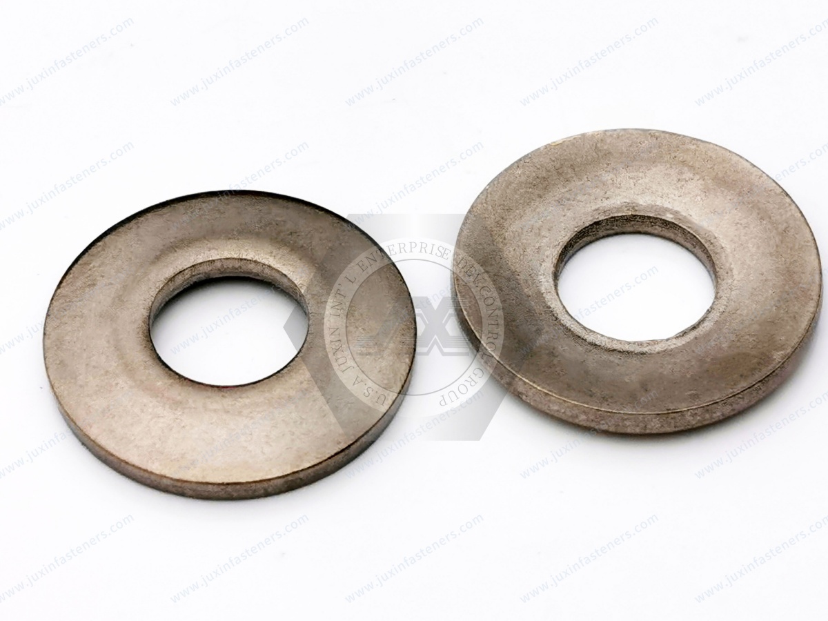
A disc spring is a conically shaped spring component loaded primarily in the axial direction.
When axial force is applied, the conical geometry deflects toward a flatter condition.
That deformation creates a spring reaction.
Unlike an ordinary flat washer, a disc spring is selected according to mechanical characteristics such as:
load;
deflection;
outside diameter;
inside diameter;
thickness;
free height;
working height;
stress;
fatigue requirement.
Therefore:
Disc Spring Selection ≠ Washer Diameter Selection
The required force-deflection behavior is a central part of the specification.
The term Belleville washer is widely used for a conical disc-shaped spring.
In engineering and commercial searches, users may use:
Belleville washer;
Belleville spring washer;
Belleville spring;
disc spring;
conical washer
for products that appear geometrically similar.
However, these search terms do not always identify the exact engineering specification.
For procurement, the product should ultimately be defined by:
standard or drawing;
dimensions;
material;
force-deflection requirement;
operating condition.
This is one of the most important distinctions in this article.
A disc spring is primarily an engineered spring component.
A conical spring washer for a bolted connection is primarily a washer used within a defined bolted-joint application.
They may both have conical geometry.
But:
Similar Shape ≠ Same Engineering Function
The applicable standard and performance requirement determine what product is actually needed.
DIN EN 16983 is an important European reference for disc springs.
It covers quality requirements and dimensions for disc springs within its defined scope.
For engineers and purchasing teams working from older drawings, an important standards update must be recognized:
DIN 2093 has been withdrawn.
Its technical content was incorporated into the European standard DIN EN 16983.
Therefore, new technical content should not continue presenting DIN 2093 as the current primary standard for standardized disc springs.
Legacy drawings may still reference DIN 2093, but new sourcing discussions should distinguish between:
Legacy DIN 2093 Requirement
and:
Current DIN EN 16983 Requirement
DIN EN 16984 addresses calculation of disc springs.
This is important because disc springs are not selected only from dimensions.
Their engineering behavior involves relationships between:
force;
deflection;
geometry;
stress;
working position.
For a performance-controlled disc spring application, calculation and force-deflection behavior are fundamental.
A useful way to understand the standards is:
DIN EN 16983 → Quality Requirements & Dimensions
DIN EN 16984 → Calculation
This distinction matters for procurement.
A buyer cannot assume that providing only:
“Belleville washer, 25 mm OD”
fully defines a spring component.
The required mechanical behavior may still be missing.
DIN 6796 covers conical spring washers for bolted connections.
This is a different engineering context from a general disc spring selected primarily from a force-deflection requirement.
DIN 6796 remains a relevant current standard for its defined product scope.
Therefore:
DIN EN 16983 Disc Spring ≠ DIN 6796 Conical Spring Washer
A procurement team should not substitute one for the other based only on similar appearance.
DIN 267-26 provides technical specifications for conical spring washers made from spring steel for bolted connections.
This standard is relevant within its defined scope and reinforces the distinction between:
engineered disc springs;
conical spring washers intended for bolted connections.
For OEM sourcing, the customer drawing or specification should identify which product family is required.
A disc spring begins with a conical free shape.
When an axial load is applied, the spring deflects.
As the cone changes geometry, the spring develops an opposing force.
The relationship between:
Applied Force (F)
and:
Deflection (s)
defines the spring's mechanical behavior.
Therefore, one of the most important engineering questions is:
How much force is required at what deflection?
Disc springs are characterized by a load-deflection relationship.
The curve depends on factors including:
outside diameter;
inside diameter;
material thickness;
free cone height;
material properties;
geometry.
This makes disc springs useful where engineers need substantial axial force within a relatively compact axial space.
But it also means:
Same OD and ID ≠ Same Spring Performance
Thickness and geometry can significantly change the force-deflection behavior.
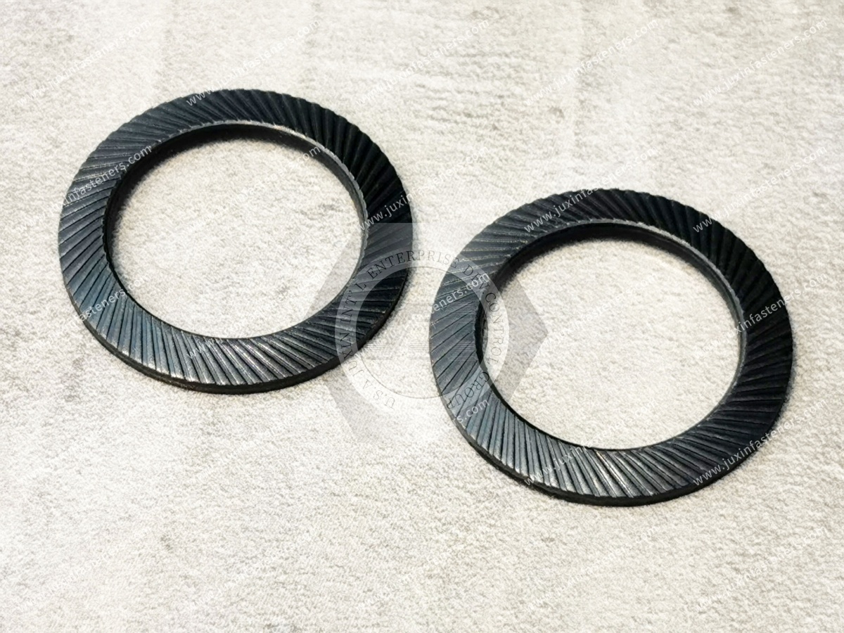
This distinction is particularly important when disc springs are used in bolted joints.
The spring reaction of the disc is not automatically equal to the preload developed in the bolt.
The complete system includes:
bolt stiffness;
clamped-part stiffness;
disc spring stiffness;
tightening method;
installed deflection;
external load.
Therefore:
Disc Spring Force ≠ Automatically Bolt Clamp Force
The entire joint must be evaluated.
Disc springs can be used in systems where additional elastic travel is useful.
In an appropriate design, they may help compensate for dimensional changes caused by factors such as:
thermal expansion;
contraction;
settlement;
wear;
gasket compression;
other controlled displacement.
Their value comes from introducing a designed spring characteristic into the assembly.
However:
Disc Spring ≠ Automatic Preload Maintenance
The spring must be correctly sized and installed within its intended operating range.
The original version of this article treated disc springs mainly as anti-loosening washers.
That is too simplistic.
A disc spring can influence the stiffness and elastic behavior of a bolted system, but rotational self-loosening is a separate phenomenon.
A joint exposed to transverse movement may still require a dedicated locking strategy.
Therefore:
Preload Compensation ≠ Rotational Locking
For rotational loosening analysis, see Do Spring Washers Prevent Bolt Loosening?.
Another important distinction:
Spring Behavior ≠ Damping
A spring stores and returns mechanical energy.
A damper dissipates mechanical energy.
Disc spring stacks can exhibit frictional hysteresis under certain configurations, particularly where sliding contact occurs,
but this should not be generalized into a claim that every disc spring is a vibration damper.
If vibration damping is required, the damping requirement should be separately defined and validated.
The old article stated that disc spring washers generally have serrated ribs or teeth.
That is incorrect as a general definition.
Standard disc springs can have smooth working surfaces.
Some locking washer products combine conical geometry with serrations or teeth, but these should be treated as a different product design.
Therefore:
Belleville Disc Spring ≠ Serrated Lock Washer
The presence of teeth must be explicitly specified.
Toothed lock washers rely on interaction between teeth and mating surfaces.
Disc springs rely primarily on controlled elastic deformation.
These are different mechanisms.
If the engineering objective is rotational locking, do not assume a smooth disc spring and a toothed locking washer are interchangeable.
Wedge-locking washer systems use paired components with engineered cam geometry to resist rotational self-loosening.
Disc springs use conical elastic deformation to produce axial spring force.
Therefore:
Disc Spring ≠ Wedge-Locking Washer
The two products solve different mechanical problems.
A single disc spring may provide the required force and travel where:
installation space is limited;
required deflection is within the capability of one disc;
required load is within the capability of one disc.
When a single spring cannot provide the required force-deflection relationship, multiple disc springs can be stacked.
One of the most useful characteristics of disc springs is that multiple discs can be arranged to modify the overall spring behavior.
Common arrangements include:
series;
parallel;
series-parallel combinations.
This gives designers substantial flexibility within a compact installation envelope.
In a series arrangement, disc springs are alternated so that their conical directions oppose one another.
For ideal identical springs:
Series Stacking → More Total Deflection
The stack can provide greater travel while approximately retaining the force characteristic of a single disc at corresponding individual-disc deflection.
Conceptually:
If one disc provides:
Force = F
at:
Deflection = s
then a series stack of identical discs can provide approximately:
Force = F
at:
Total Deflection = n × s
subject to actual stack behavior, tolerances and friction.
Series stacking can be useful when an application needs:
more axial travel;
greater displacement compensation;
a lower effective stack spring rate;
controlled force over a larger movement range.
The actual stack still requires engineering evaluation.
In a parallel arrangement, multiple disc springs are nested in the same orientation.
For ideal identical springs:
Parallel Stacking → More Force
Conceptually, if one disc provides:
Force = F
at:
Deflection = s
then a parallel group of identical discs can provide approximately:
Force = n × F
at approximately:
Deflection = s
However, real parallel stacks include friction between contacting surfaces.
Therefore actual force-deflection behavior can differ from the ideal calculation.
Nested disc springs slide relative to each other as they deflect.
This creates friction.
Friction can influence:
loading force;
unloading force;
hysteresis;
heat generation;
repeatability;
fatigue behavior.
This means:
Theoretical Stack Force ≠ Automatically Actual Stack Force
Surface finish, lubrication and stack configuration can matter.
Where both additional force and additional travel are required, engineers can combine series and parallel arrangements.
For example, groups of parallel discs can be arranged in series.
This allows designers to tailor:
total force;
total travel;
effective spring rate;
installation height.
However, more complicated stacks also introduce additional variables such as friction, tolerances and alignment.
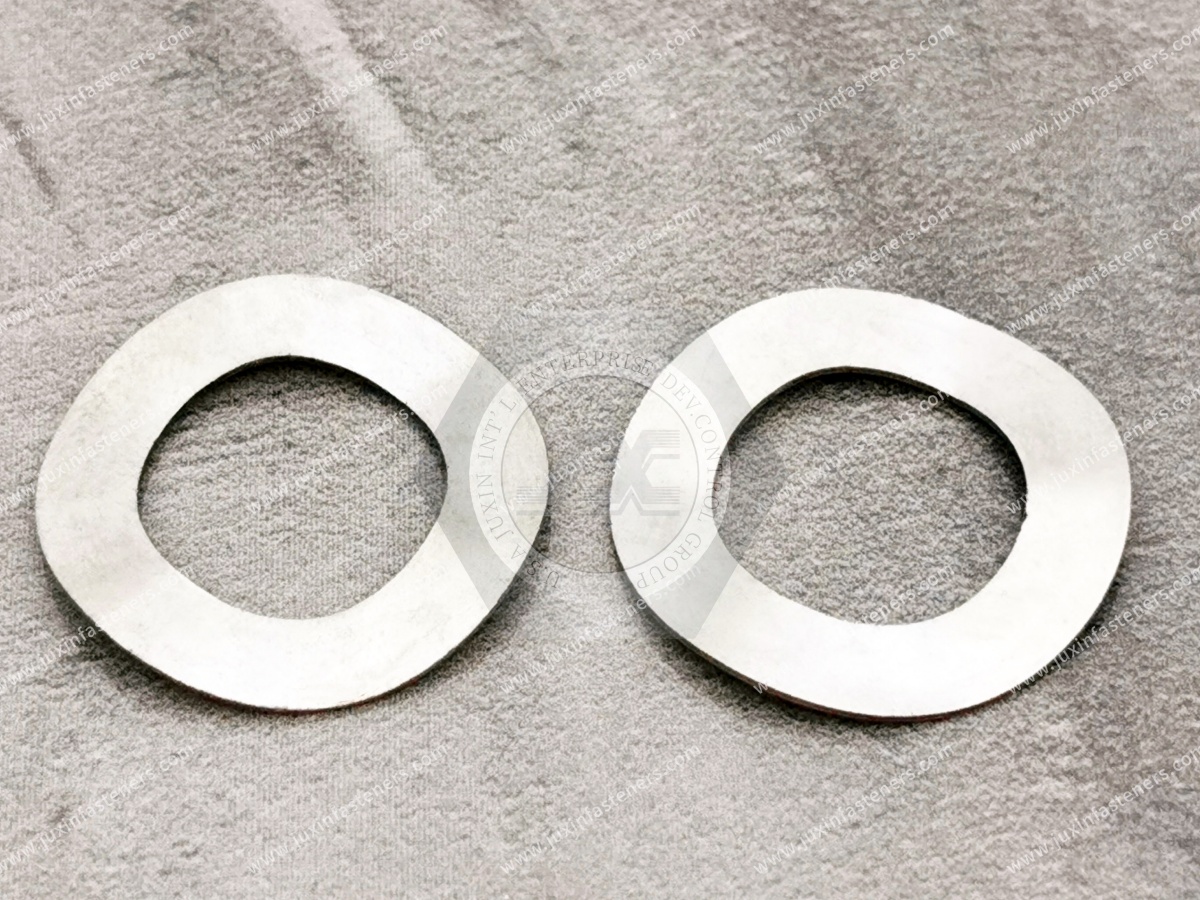
For procurement, specifying only:
“10 Belleville washers”
may not be enough.
The assembly may depend on whether those ten springs are arranged:
all in series;
all in parallel;
as parallel pairs in series;
in another controlled combination.
The stack orientation can fundamentally change system performance.
The drawing or assembly instruction should clearly show the required orientation.
Incorrect stack orientation can produce a completely different load-deflection characteristic.
This is a production-control issue, not merely an engineering calculation issue.
A disc spring should not automatically be compressed completely flat during normal cyclic operation.
As deflection increases, stress changes within the disc.
High working deflection can reduce fatigue capability.
Therefore engineers should define:
preload position;
operating position;
maximum deflection;
required travel.
The required working range should come from the actual application and applicable calculation method.
The original article implied that the disc spring should simply compress toward flat under tightening.
For some products and applications, flattening may be part of a defined condition.
For others, especially dynamically loaded disc springs, repeatedly operating near or beyond extreme deflection can increase stress and reduce fatigue performance.
Therefore:
Flat Condition ≠ Universal Installation Target
Follow the applicable spring calculation, standard, drawing or supplier engineering data.
Disc springs used under dynamic cyclic loading require fatigue consideration.
Fatigue behavior depends on factors including:
stress range;
preload;
final deflection;
material;
surface condition;
manufacturing quality;
operating temperature;
number of cycles.
The difference between minimum and maximum operating stress is particularly important.
Increasing the working deflection of a disc spring generally increases stress.
Where the application cycles between two operating positions, a larger stress range can reduce fatigue life.
Therefore:
Maximum Travel ≠ Maximum Durability
The spring should be designed around the required operating range rather than simply using all available deflection.
Disc springs can be used under different loading conditions.
The spring may remain loaded for long periods or experience relatively few load changes.
Important considerations can include:
force;
deflection;
relaxation;
temperature.
The spring repeatedly cycles between load conditions.
Additional considerations include:
stress range;
cycle count;
fatigue;
friction;
heat generation;
lubrication where applicable.
The same spring should not automatically be assumed suitable for both conditions.
A spring maintained under load can experience changes in force over time depending on:
material;
stress;
temperature;
duration.
For long-term preload applications, relaxation can therefore matter.
The required force should not be specified only at initial installation if long-duration performance is critical.
Operating temperature can affect:
spring material properties;
relaxation;
fatigue behavior;
corrosion;
lubrication.
High-temperature applications may require a different material than ordinary spring steel.
Do not select disc spring material only from room-temperature catalog data when service temperatures are significant.
Disc springs can be manufactured from different spring materials depending on application requirements.
Selection can involve:
spring steel;
corrosion-resistant alloys;
stainless spring materials;
high-temperature alloys;
customer-specified materials.
The material must be appropriate for the required:
stress;
fatigue;
corrosion resistance;
temperature;
environment.
The old article presented 65Mn as a typical default disc spring material.
For an international B2B engineering page, that is not an appropriate universal specification.
Material should instead be defined by:
applicable international material specification;
disc spring standard;
customer drawing;
required mechanical properties;
operating environment.
JUXIN FASTENERS can evaluate material requirements according to the specific project rather than forcing one domestic material designation into every application.
Spring steel components may require surface protection depending on the environment.
Possible project-specific surface treatments can include appropriate:
phosphate-based systems;
zinc-based coatings;
other engineered coatings.
However, coating selection must consider both corrosion and mechanical behavior.
A coating process should not be specified without considering the spring material and required fatigue performance.
High-strength spring components require careful process control when coating processes introduce hydrogen.
Hydrogen-embrittlement susceptibility depends on factors including:
material strength/hardness;
manufacturing condition;
surface treatment;
applied stress;
process conditions.
There is no universal post-plating bake schedule that can safely be applied to every disc spring.
Coating requirements should follow the material, process and customer specification.
Disc springs transfer significant loads through relatively narrow contact regions.
The mating surfaces therefore matter.
Engineers should evaluate:
surface hardness;
flatness;
roughness;
alignment;
wear;
lubrication where applicable.
A correctly calculated spring can still perform poorly if its supporting surfaces are unsuitable.
Long disc spring stacks may require guidance to maintain alignment.
Depending on the arrangement, guidance may be provided through:
an internal guide;
an external guide;
engineered assembly geometry.
Clearance must account for dimensional changes as the discs deflect.
Too much clearance can reduce alignment control.
Too little clearance can cause interference.
The old article stated:
“The concave side should face the connected component and the convex side should face the nut.”
That is not a universal rule for disc springs.
For a single symmetrical application, orientation may be defined by the assembly design.
For stacks, orientation is deliberately changed to create series, parallel or combination behavior.
Therefore:
Disc Spring Orientation Depends on the Required Stack Configuration
Follow the drawing rather than a generic concave-side installation rule.
Disc springs should not automatically be classified as either reusable or non-reusable.
Reuse depends on:
permanent deformation;
corrosion;
wear;
cracking;
surface damage;
prior loading;
fatigue history;
application requirements.
For critical applications, the customer's maintenance and inspection specification should control reuse.
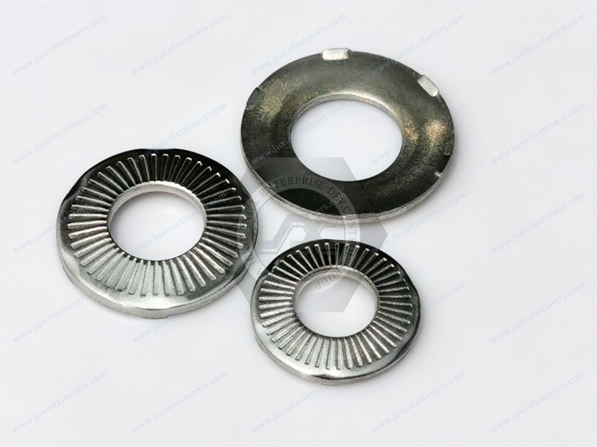
One important application of disc springs is adding elastic compliance to a bolted system.
This may be useful where the assembly experiences controlled dimensional change.
Potential examples can involve:
thermal expansion;
gasket settlement;
wear;
equipment movement;
differential expansion.
However, the complete bolted-joint stiffness model should be considered.
Different materials expand at different rates when temperature changes.
In some engineered assemblies, a disc spring can provide additional elastic travel so that force changes caused by thermal movement can be better managed.
But:
Disc Spring ≠ Automatic Thermal Compensation
The expected displacement and force change must be calculated.
Some gasketed assemblies can experience compression or relaxation over time.
Disc springs may be considered where additional elastic travel is required to manage load changes.
However, sealing performance depends on the complete system:
gasket;
flange;
fastener;
preload;
temperature;
pressure;
surface condition.
A disc spring alone does not guarantee leak-tightness.
Disc springs can be used in engineered valve and piping-related mechanisms where compact axial spring force is required.
Applications can involve:
valve mechanisms;
pressure-control mechanisms;
supports;
actuators;
equipment assemblies.
The exact use should follow the equipment design and applicable engineering requirements.
Disc springs can be used in machinery requiring controlled axial force within limited space.
Potential applications can include:
clamping mechanisms;
brake mechanisms;
clutch mechanisms;
machine tools;
overload systems;
bearing systems;
actuators.
Selection should follow the required force-deflection curve rather than simply nominal diameter.
Disc springs appear in different automotive mechanical systems where compact spring force is required.
Potential applications may involve:
clutch mechanisms;
brake-related mechanisms;
actuators;
transmission-related equipment;
controlled mechanical assemblies.
Safety-critical automotive applications require exact drawing, material, validation and customer approval.
A generic industrial Belleville washer should not automatically be represented as suitable for a safety-critical vehicle system.
Disc springs can potentially be used in controlled mechanical interfaces where equipment experiences:
thermal expansion;
dimensional variation;
preload change.
Possible equipment areas can include:
power electronics;
thermal-management equipment;
electrical assemblies;
mechanical mounting systems.
However, they should not automatically be represented as:
electrical contacts;
grounding devices;
busbar fasteners;
IP sealing components.
Those functions require separate engineering specifications.
AI data centers, HPC systems, UPS equipment, power conversion systems and cooling infrastructure can contain mechanical assemblies exposed to thermal cycling and equipment vibration.
Where a controlled spring force is required, disc springs may be evaluated as part of the mechanical system.
The application should be defined from force and displacement requirements rather than industry name alone.
Energy equipment can contain mechanisms where high axial force, limited installation space or dimensional compensation are required.
Potential applications can include:
braking mechanisms;
equipment actuators;
mechanical clamping systems;
service assemblies.
Critical wind-turbine bolted joints require project-specific engineering and qualification.
A generic disc spring should not automatically be represented as suitable for structural turbine joints.
Construction, mining and agricultural equipment can use disc springs in mechanical systems involving:
brakes;
clutches;
overload protection;
actuators;
heavy-duty mechanisms.
Shock and cyclic loading make fatigue and material selection important.
Railway equipment may use disc springs in mechanical mechanisms requiring compact axial spring force.
However, safety-critical rail applications require the applicable railway specification, component qualification and validation.
General industrial supply should not be represented as automatically rail-qualified.
HVAC equipment can contain:
compressors;
pumps;
valves;
thermal systems;
mechanical actuators.
Disc springs may be considered where controlled axial force or dimensional compensation is required.
The actual operating temperature and cycle requirements should be defined.
Automation equipment may use disc springs in:
clamping systems;
tooling;
actuators;
positioning mechanisms;
overload protection;
precision assemblies.
Their compact axial envelope can be useful where conventional coil springs require too much space.

Disc springs may be used in mechanical parts of:
laboratory equipment;
diagnostic equipment;
positioning mechanisms;
equipment housings;
mechanical actuators.
A generic disc spring should not automatically be described as medically certified, biocompatible, sterile or cleanroom-qualified.
Those requirements must be separately specified.
Disc springs can be used in aerospace mechanisms when manufactured and qualified to the required specification.
However, generic industrial disc springs should not be promoted as flight-critical or defense-qualified products without the applicable:
material specification;
manufacturing controls;
inspection;
traceability;
qualification.
For JUXIN FASTENERS, aerospace-related inquiries should be evaluated from the actual drawing and project requirement.
| Engineering Requirement | Selection Direction |
|---|---|
| Compact axial spring force | Evaluate disc spring |
| More travel at similar force | Series stack |
| More force at similar deflection | Parallel stack |
| More force and more travel | Series-parallel combination |
| Bolted-joint conical spring washer | Evaluate DIN 6796 / applicable drawing |
| Standardized disc spring | Evaluate DIN EN 16983 |
| Disc spring calculation | Use DIN EN 16984 / engineering calculation |
| Dynamic cyclic application | Evaluate stress range and fatigue |
| Long-term static loading | Evaluate relaxation |
| Elevated temperature | Evaluate temperature-compatible material |
| Corrosive environment | Evaluate material + coating |
| Rotational self-loosening | Evaluate dedicated locking strategy |
Two disc springs with similar diameters can have very different force-deflection characteristics.
DIN 6796 conical spring washers and DIN EN 16983 disc springs serve different specification contexts.
DIN 2093 has been withdrawn and incorporated into the European DIN EN 16983 framework.
Working deflection should follow the application design.
Spring force and rotational locking are different functions.
Series and parallel arrangements produce very different mechanical behavior.
Nested discs introduce sliding friction and hysteresis.
Dynamic applications require evaluation of stress range and cycle requirements.
A performance-controlled spring also requires force-deflection information.
Orientation depends on the required stack arrangement and assembly design.
Engineers may search:
Belleville washer load calculation;
disc spring force calculation;
disc spring stack calculation;
Belleville washer stacking;
disc springs in series vs parallel;
DIN EN 16983 disc spring;
DIN 6796 washer;
disc spring fatigue life;
Belleville washer preload;
disc spring for thermal expansion.
These searches indicate an engineering-selection task rather than simple product browsing.
Procurement and supplier-development teams may search:
disc spring manufacturer;
Belleville washer supplier;
Belleville spring manufacturer;
DIN EN 16983 disc spring supplier;
DIN 6796 washer supplier;
custom disc spring manufacturer;
industrial disc spring supplier;
OEM Belleville washer supplier.
Commercial sourcing should begin only after the engineering requirement has been sufficiently defined.
A request such as:
“Need Belleville washer, M12.”
may be insufficient.
The supplier may still need:
outside diameter;
inside diameter;
thickness;
free height;
required force;
required deflection;
material;
surface treatment;
operating temperature;
static or dynamic loading;
quantity.
This is why spring sourcing must connect engineering and procurement.
For technical evaluation by JUXIN FASTENERS, provide as much of the following as available:
2D drawing;
3D model where relevant;
physical sample;
customer part number;
existing/reference part number;
required standard;
DIN EN 16983 requirement where applicable;
DIN 6796 requirement where applicable;
legacy DIN 2093 reference where applicable;
outside diameter;
inside diameter;
thickness;
free height;
installed height;
required preload force;
required operating force;
required deflection;
minimum working position;
maximum working position;
single disc or stack;
stack configuration;
number of discs;
static or dynamic loading;
expected cycle count;
fatigue requirement;
relaxation requirement;
material;
material specification;
hardness where applicable;
surface treatment;
corrosion requirement;
operating temperature;
chemical environment;
lubrication requirement where applicable;
guide dimensions;
mating-surface requirements;
application description;
safety classification where applicable;
sample quantity;
production quantity;
annual demand;
inspection requirements;
packaging requirements;
labeling requirements;
customer-specific requirements.
The terms are frequently used interchangeably in the market.
However, the actual component should be identified from its standard, dimensions and force-deflection requirements.
DIN 2093 has been withdrawn.
Its disc-spring quality and dimensional requirements were incorporated into DIN EN 16983.
Legacy drawings can still reference DIN 2093 and may require replacement to the original specification.
DIN EN 16984 provides calculation methods for disc springs.
It is important when force, deflection and stress need to be determined.
No.
DIN 6796 covers conical spring washers for bolted connections.
DIN EN 16983 addresses disc springs within its own scope.
Series stacking increases available total deflection while approximately maintaining the force behavior of an individual identical disc at the corresponding individual deflection.
Parallel stacking increases available force at approximately the same deflection, although friction between nested discs affects real behavior.
Yes.
Combination stacks can be designed to achieve both additional force and additional travel.
No.
The required installed deflection depends on the spring design and application.
Complete flattening is not a universal installation rule.
Not automatically.
A disc spring can alter the elastic behavior of the joint, but rotational self-loosening may require a separate locking strategy.
They can be used in engineered systems where additional elastic travel is required to accommodate controlled dimensional change.
The expected displacement and force variation must still be calculated.
Reuse depends on application requirements and the component's condition, loading history, deformation, fatigue, wear and corrosion.
Do not assume universal reusability.
The most important information is not simply diameter.
Provide the required force, deflection, dimensional envelope, loading cycle, environment and applicable drawing or standard.
An engineer may begin with:
“How do I increase Belleville washer force?”
A procurement manager may begin with:
“Need disc spring supplier.”
A mature sourcing process connects the two:
Required Force → Required Travel → Installation Envelope → Single Disc / Stack → Series / Parallel Configuration → Material
→ Fatigue & Environment → Standard / Drawing → Prototype Validation → Approved Specification → Supplier RFQ
That is the commercial path from engineering search to production sourcing.
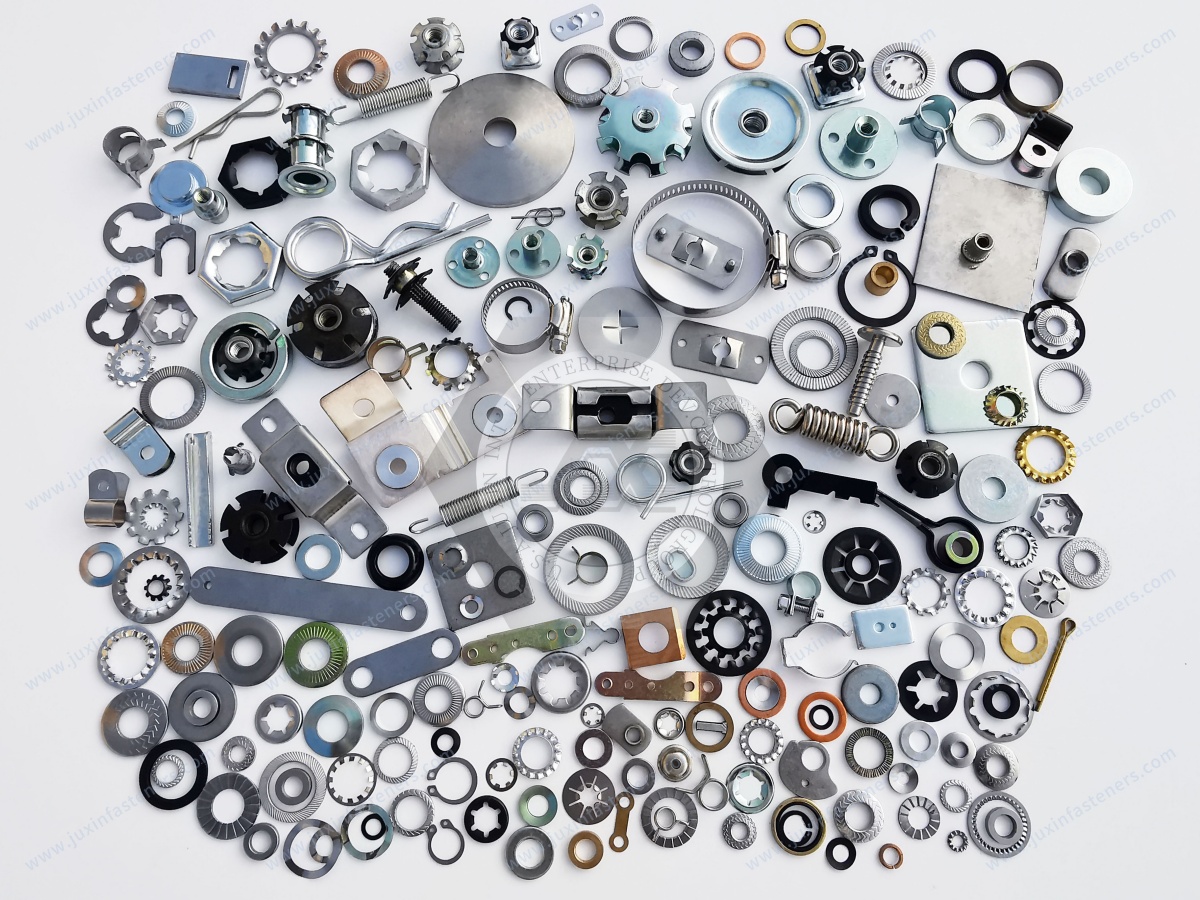
JUXIN FASTENERS supports OEM sourcing of disc springs, conical spring washers, industrial washers and related bolts, nuts,
screws and custom fastening components for machinery, automotive equipment, power systems, industrial automation, HVAC, heavy equipment and other engineered applications.
For broader washer selection, see Industrial Washers: Types, Functions & Selection Guide.
For washer-function comparison, see Flat Washer vs Spring Washer vs Lock Washer: Selection Guide.
For vibration-loosening analysis, see Do Spring Washers Prevent Bolt Loosening?.
For complete bolted-joint selection, see Washers and Bolts: Fastening Systems Selection Guide.
For disc spring and Belleville washer RFQs, send your drawing, standard, dimensions, required force, deflection, stack configuration, material, operating environment and estimated demand to:
The correct disc spring is not selected simply because its hole fits the bolt.
It is selected because its force, deflection, geometry, material and operating range match the mechanical system.
 MORE NEWS

Sep. 25, 2026

Sep. 25, 2026

Sep. 25, 2026
Contact Us
Tel.:
+86 020 8621 0320
+86 020 3121 6067
E-mail:
Technical Support:
Navigation
SEND INQUIREY