
Call Us
+86 136 6007 9809
Call Us
+86 136 6007 9809

Sep. 29, 2023
DIN 6799 E-clips are compact external retaining rings designed for radial installation into grooves on shafts, pins and axles.
Also known as E-type retaining rings, E-rings, E-clips or E-type circlips, these components create an axial retaining shoulder that helps keep gears, rollers,
bearings, bushings, linkages and other mounted components in their intended position.
Their distinctive advantage is assembly direction.
Unlike many conventional external circlips that must be expanded and moved axially over the end of a shaft, an E-clip can be installed radially from the side of the shaft into a correctly designed groove.
That difference can simplify assembly, reduce required axial access and make E-clips particularly useful in compact or high-volume mechanisms.
However, an E-clip should not be selected by shaft diameter alone. Groove geometry, axial load, shaft material, ring material, rotational speed, installation method and service environment all influence retention performance.
JUXIN FASTENERS supplies DIN 6799 E-clips, E-type retaining rings and other standard and drawing-based retaining components for industrial OEM applications.
For drawings, specifications, material requirements and RFQs, contact info@juxinfasteners.com.
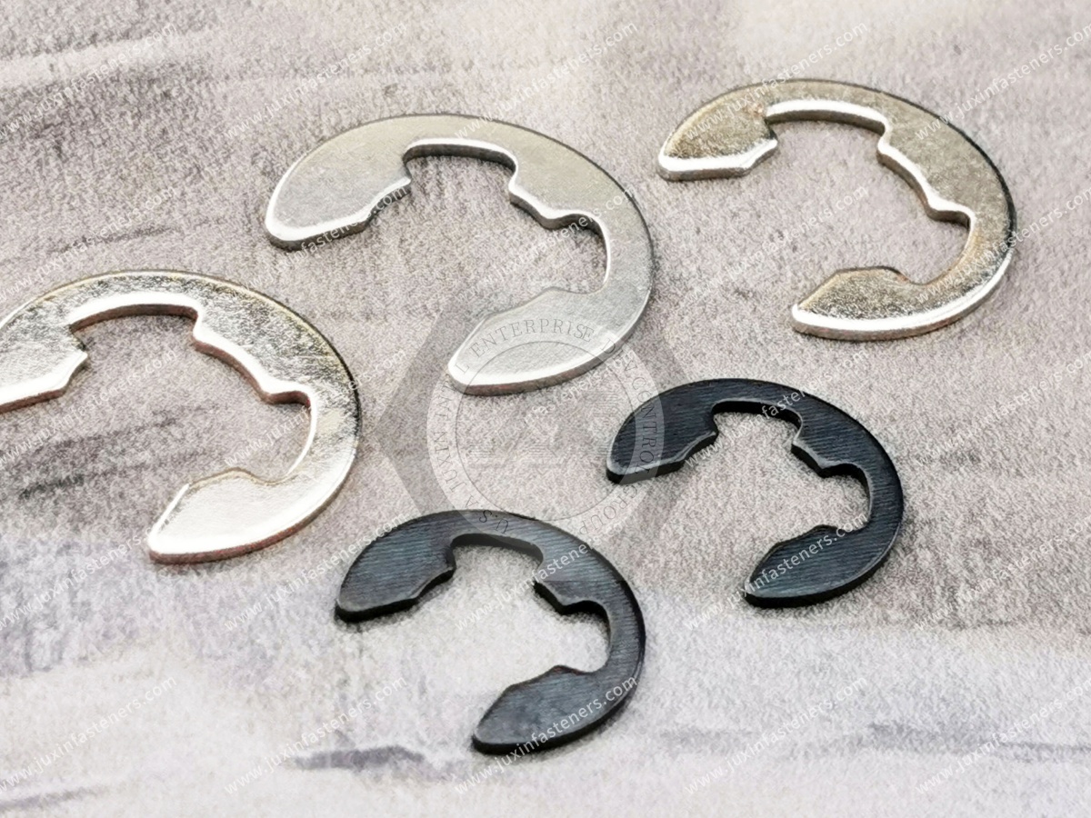
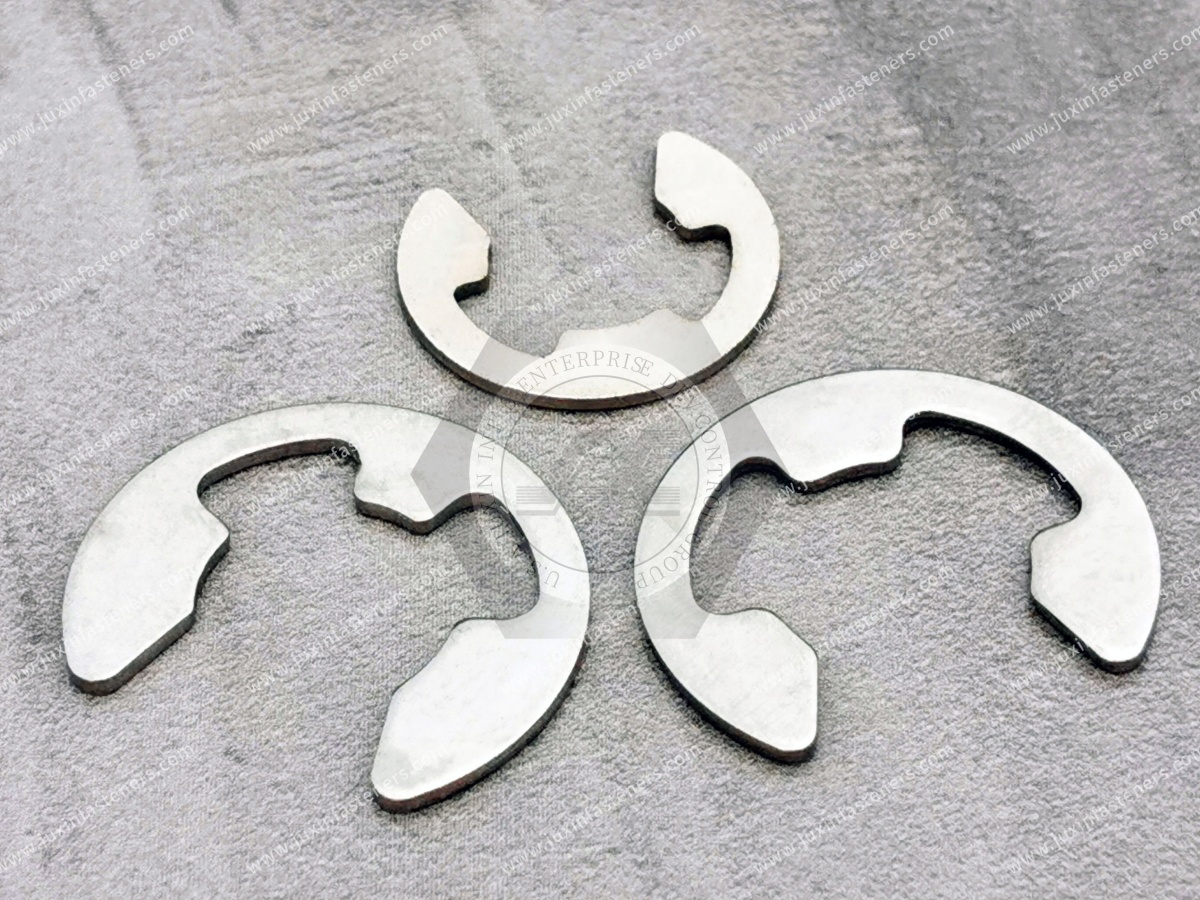
A DIN 6799 E-clip is an external retaining component designed to engage a circumferential groove on a shaft.
Viewed from the side, the ring has a characteristic E-shaped profile.
Its multiple contact regions engage the groove after the clip is pushed radially onto the shaft.
Once installed, the portion of the clip extending beyond the groove forms an axial retaining shoulder.
Typical search terms include:
DIN 6799 E-clip
DIN 6799 retaining ring
E-type retaining ring
E-ring
E-type circlip
shaft E-clip
radial retaining ring
shaft retaining clip
E-clip fastener
For engineering procurement, DIN 6799 or an approved customer drawing should be used to define the actual product rather than relying solely on the generic term "E-clip."
Radial installation is one of the most important engineering differences between an E-clip and many conventional external retaining rings.
The E-clip approaches the shaft from the side and is pushed directly into the groove.
This can eliminate the need to:
access the end of the shaft;
slide a ring along the entire shaft;
remove other components already installed on the shaft;
provide large axial assembly clearance.
This is especially valuable when the shaft end is:
blocked by another component;
difficult to reach;
already assembled into a mechanism;
located inside compact equipment.
For manufacturing engineers, this can make the E-clip not only a retention component but also an assembly-process decision.
Both components can retain parts axially on shafts, but they should not be treated as interchangeable.
Typically:
installs radially;
has an open E-shaped geometry;
is well suited to compact shaft and pin assemblies;
can support rapid installation;
does not require axial access from the shaft end.
Typically:
has a more complete circular ring geometry;
is expanded during installation;
is commonly installed over the shaft end;
often uses dedicated circlip pliers;
is used across a broad range of shaft-retention applications.
The best choice depends on axial load, available space, groove geometry, shaft size, assembly method and service requirements.
This comparison is important because replacing one style with another without redesigning the groove can create an unsafe retention system.
A common installation mistake is assuming that every external retaining ring requires snap-ring pliers.
DIN 6799 E-clips are generally installed by pushing the clip radially into the shaft groove using an appropriate installation tool, applicator or assembly fixture.
Depending on production volume, installation can use:
manual E-clip installation tools;
controlled push tools;
dedicated applicators;
automated feeding and insertion equipment.
The clip should not be unnecessarily opened or distorted during installation.
This matters because excessive deformation can permanently alter its geometry and reduce groove engagement.
An E-clip forms part of a mechanical load path.
When a retained component applies axial force to the clip, the load is transferred through:
retained component → E-clip → groove wall → shaft
This means the clip is only one part of the retention system.
The groove and shaft must also be capable of carrying the required load.
A stronger E-clip cannot compensate for an incorrectly dimensioned or mechanically weak groove.
The shaft groove determines how the E-clip seats and transfers axial load.
Important groove characteristics include:
groove diameter
groove width
groove position
edge geometry
surface finish
dimensional tolerance
The applicable DIN 6799 dimensions or approved customer drawing should be followed.
An approximate groove that merely "looks close" can reduce retention capability.
Groove diameter influences the depth of engagement between the E-clip and shaft.
A groove that is too shallow may not allow secure seating.
A groove that is too deep can alter clip support and installed geometry.
The correct dimension should therefore be controlled as a functional shaft characteristic.
Groove width must allow the E-clip to seat properly without excessive axial movement.
Too narrow a groove can prevent complete insertion.
Too wide a groove can increase axial play.
For precision mechanisms, this clearance can affect positioning accuracy.
The axial position of the groove determines where the retained component stops.
This means groove-location tolerance can be just as important as the E-clip itself.
In applications involving gears, rollers, bearings or linkages, excessive positional tolerance can create:
unwanted end play
misalignment
noise
inconsistent mechanism operation
For precision assemblies, engineers should therefore tolerance the complete stack-up rather than considering only ring dimensions.
An E-clip manufactured from high-strength spring steel may be stronger than the shaft groove into which it is installed.
This becomes particularly important with:
aluminum shafts or pins;
soft carbon steel;
polymer shafts;
thin sections;
miniature components.
Under axial load, the groove wall can deform or shear before the clip itself fails.
Therefore, axial retention capacity is determined by the clip-and-groove system, not by the E-clip alone.
A thicker clip may appear stronger, but actual retention performance depends on several interacting factors:
clip material
heat treatment
clip geometry
groove engagement
shaft material
groove dimensions
retained-component contact geometry
static or dynamic loading
For OEM applications, catalog thickness should not be used as the only indicator of load capacity.
Carbon spring steel is widely used for E-type retaining rings because it can provide the elastic recovery needed for radial installation and groove retention.
Important properties include:
spring elasticity
strength
hardness
fatigue resistance
dimensional stability
Final mechanical performance depends on the selected material, heat treatment and geometry.
For international OEM specifications, it is generally more useful to define the required spring-steel material and mechanical properties than to rely on a local material designation.
Stainless steel E-clips may be selected when corrosion resistance is an important application requirement.
Potential environments include:
foodservice equipment
outdoor machinery
humid equipment
cooling systems
medical-related equipment subject to applicable qualification
certain marine-related assemblies
The stainless steel grade should be selected according to actual corrosion exposure.
Stainless steel should not automatically be substituted for hardened carbon spring steel without checking mechanical requirements and groove interaction.
Carbon steel E-clips may use protective finishes such as:
phosphate coatings
zinc-based coatings
zinc-flake coatings
other customer-specified finishes
Surface treatment should be selected according to:
corrosion exposure
coating thickness
dimensional tolerance
installation wear
environmental compliance
Because E-clips flex during installation, coating adhesion and durability are relevant considerations.
E-clips are small precision components.
Even a relatively thin coating can become significant where the groove fit is tightly controlled.
Excessive coating build can affect:
clip thickness
insertion force
seating
axial clearance
surface interaction
OEM drawings should clarify whether critical dimensions apply before or after coating when necessary.
For high-volume manufacturing, installation force can provide useful information about assembly consistency.
An unexpectedly high insertion force may indicate:
incorrect groove dimensions
wrong clip size
excessive coating
tool misalignment
component interference
An unusually low installation force may indicate:
an oversized groove
incorrect clip
damaged clip
insufficient engagement
For automated production, monitoring installation conditions can therefore help identify assembly problems before they become field failures.
After installation, the clip should be fully seated in the intended groove.
A partially engaged E-clip may appear installed but have substantially reduced retention capability.
Production controls may include:
visual inspection
camera inspection
mechanical presence checks
controlled installation stroke
automated force/displacement monitoring
The appropriate method depends on assembly criticality and production volume.
E-clips can be used on rotating shafts, but rotational speed must be considered.
Centrifugal force acts outward on an external retaining ring.
As shaft speed increases, this force can reduce effective groove engagement.
High-speed applications therefore require evaluation of:
rotational speed
clip geometry
clip mass
shaft diameter
groove depth
material
This is particularly important in:
electric motors
high-speed pumps
small rotors
spindle mechanisms
rotating automation equipment
A clip that works reliably on a stationary pin is not automatically appropriate for a high-speed motor shaft.
E-clips may encounter more than static axial forces.
Repeated impact, vibration or reversing axial loads can create:
groove wear
clip fatigue
fretting
progressive deformation
Dynamic applications should therefore be evaluated according to actual service loading rather than only maximum static force.
The retained component contacts the E-clip and transfers axial force into it.
A sharp or poorly supported contact edge can create high localized stress.
Engineers should therefore consider:
contact diameter
edge radius
bearing area
axial clearance
component hardness
In some assemblies, an additional washer or spacer may improve load distribution between the retained component and E-clip.
E-clips can be used in assemblies containing bearings, but they should not automatically be treated as precision bearing-preload devices.
An E-clip may provide axial retention while another feature controls:
bearing preload
axial clearance
thrust load
thermal expansion
Depending on the bearing system, additional components may include:
spacers
thrust washers
shoulders
spring elements
locknuts
The complete bearing arrangement should determine the retention strategy.
An E-clip does not automatically create zero axial movement.
The actual end play depends on:
groove position
groove width
clip thickness
retained-component dimensions
stack-up tolerances
Where axial positioning is critical, engineers should calculate the tolerance stack rather than assuming that installing an E-clip eliminates movement.
E-type retaining rings can be found in many compact automotive mechanisms.
Potential applications include:
actuator assemblies
linkages
small gear systems
motor assemblies
pump mechanisms
seat and interior mechanisms
thermal-management equipment
electromechanical systems
For EV platforms, E-clips may also be used in auxiliary motors, pumps, actuators and cooling-system components.
Safety-critical vehicle applications require OEM-approved specifications and validation.
A standard DIN 6799 clip should not automatically be treated as qualified for braking, steering or other safety-critical systems.
Electric motors frequently contain compact shaft and bearing assemblies.
E-clips may provide axial retention in suitable designs where:
space is limited;
radial installation is advantageous;
axial loads are moderate;
rotational speed has been evaluated.
High-speed motor designs require particular attention to centrifugal effects and groove engagement.
E-clips are well suited to compact mechanisms where assembly speed and space efficiency matter.
Potential uses include:
pivot pins
rollers
small shafts
actuators
linkages
robotic mechanisms
conveyor components
Radial installation can be particularly useful where the shaft end becomes inaccessible after assembly.
Pumps and valve mechanisms can contain small shafts, pins and actuators requiring axial retention.
E-clips may be used where the load, corrosion environment and service conditions are appropriate.
The clip itself is not a sealing element; its role is mechanical retention.
Modern liquid-cooling infrastructure contains pumps, fans, actuators, valves and small mechanical mechanisms.
E-type retaining rings may be used within:
pump mechanisms
fan assemblies
motor shafts
valve actuators
cooling equipment
control mechanisms
For these systems, material selection should account for humidity, coolant exposure and equipment service life.
Fans, blowers, actuators, dampers and control mechanisms often use small shafts and pins.
DIN 6799 E-clips can provide compact axial retention where radial installation and rapid assembly are useful.
Rotational speed should be evaluated for fan and motor shafts.
High-volume equipment manufacturing often benefits from fast radial clip installation.
Applications can include:
foodservice equipment
vending equipment
office machinery
commercial appliances
small motors
control mechanisms
For production engineers, installation speed and automation compatibility can be as important as the unit cost of the clip.
E-clips can also be used in appropriate linkages, pins and mechanisms in agricultural and off-highway equipment.
However, applications exposed to heavy impact, mud, corrosion or severe axial loading require careful assessment of:
groove strength
clip retention
coating
service access
For highly loaded joints, a more robust positive-retention method may be preferable.
E-type retaining components can exist in aerospace and medical mechanisms, but these sectors require controlled materials, traceability, validation and customer approval.
A commercial DIN 6799 E-clip should not be described as automatically aerospace- or medical-qualified.
Such applications require the applicable approved specification.
An E-clip may be particularly useful when:
radial installation is preferred;
shaft-end access is unavailable;
assembly space is limited;
production volume is high;
installation speed matters;
the shaft or pin is relatively compact;
axial loads are within the validated retention capability.
These characteristics make E-clips attractive in high-volume mechanical assemblies.
Another retention method may be more appropriate when:
axial loads are very high;
shaft speed is extremely high;
the groove significantly weakens the shaft;
the clip could be exposed to accidental side impact;
zero axial play is required;
frequent field removal is expected;
positive mechanical retention is required.
Alternatives can include:
DIN 471 external retaining rings
shaft collars
locknuts
cotter pins
end plates
threaded retainers
custom retaining components
The correct choice depends on the complete assembly rather than the clip price alone.
One of the strongest commercial advantages of E-clips is their suitability for high-volume assembly.
Depending on product geometry and production volume, clips can be:
bowl-fed;
rail-fed;
magazine-fed;
automatically positioned;
inserted with controlled tooling.
This can reduce assembly time compared with retention methods requiring threaded components.
However, automation requires consistent:
clip geometry
groove dimensions
feeding orientation
insertion force
surface finish
For OEM programs, these manufacturing requirements should be discussed during supplier development rather than after production tooling is completed.
A practical selection process should include the following.
Determine the nominal shaft or pin size.
Use the applicable standard dimensions or approved drawing.
Confirm:
groove diameter
groove width
groove position
tolerance
Determine whether loading is:
static
cyclic
reversing
impact
Check whether the groove material can carry the required axial load.
Evaluate centrifugal effects for rotating shafts.
Choose according to mechanical and environmental requirements.
Determine whether installation will be:
manual
semi-automatic
fully automated
This helps ensure the component is selected for both engineering performance and manufacturing efficiency.
A professional E-clip RFQ should define more than nominal shaft diameter.
Procurement teams should provide:
DIN 6799 designation or customer drawing
nominal shaft size
groove dimensions
ring dimensions
material
hardness or mechanical requirements where specified
surface finish
corrosion requirements
annual volume
order quantity
installation method
inspection requirements
documentation requirements
packaging
delivery schedule
For automated assembly, packaging and feeding orientation may also become part of the purchasing specification.
Depending on the drawing and application, inspection can include:
ring thickness
radial dimensions
opening geometry
material
hardness
heat-treatment condition
coating
surface condition
burr control
functional fit
For high-volume OEM programs, functional gauges or controlled installation tests may be used in addition to dimensional inspection.
DIN 6799 covers a widely used standard E-ring configuration.
Some assemblies, however, require:
non-standard shaft sizes
different radial profiles
special thickness
custom material
special coating
altered contact geometry
application-specific retention force
For these projects, a drawing-based stamped retaining component may be more appropriate than forcing the assembly around a standard catalog ring.
JUXIN FASTENERS can review standard and custom retaining components according to customer drawings and application requirements.
For an accurate quotation, provide:
DIN 6799 designation or drawing
nominal shaft diameter
groove diameter
groove width
groove location tolerance if critical
ring thickness
material
hardness requirement if applicable
surface treatment
corrosion requirement
axial load if known
shaft rotational speed if applicable
shaft material
installation method
annual usage
order quantity
inspection requirements
documentation requirements
packaging requirements
target delivery schedule
For non-standard E-rings, a 2D drawing or existing sample can accelerate engineering review.
JUXIN FASTENERS supports industrial OEM and supply-chain customers requiring standard and custom mechanical fastening components.
Our retaining and fastening portfolio includes:
DIN 6799 E-clips
external retaining rings
internal retaining rings
circlips
snap rings
spring washers
disc spring washers
locking washers
lock nuts
high-strength bolts and nuts
self-clinching fasteners
blind rivet nuts
weld fasteners
threaded inserts
custom stamped components
CNC-machined parts
This allows engineering and procurement teams to evaluate retention requirements together with the broader fastening architecture of an assembly.
It is an E-shaped external retaining component designed for radial installation into a groove on a shaft or pin to provide axial retention.
Both are retaining components, but their geometry and installation methods can differ. DIN 6799 E-clips are installed radially, while many conventional external circlips are expanded and installed over the shaft end.
Not normally in the same way as conventional circlips. E-clips are typically pushed radially into the shaft groove using an appropriate installation tool or automated applicator.
Radial installation allows fast assembly without requiring access to the end of the shaft.
Clip geometry, material, groove geometry, shaft material, retained-component geometry and loading conditions all contribute to retention performance.
Yes in appropriate applications, but shaft speed should be evaluated because centrifugal force can affect external ring engagement.
Not automatically. Material substitution should consider elasticity, strength, hardness, corrosion requirements and the approved design.
Not necessarily. End play depends on groove position, groove width, clip thickness and the tolerance stack of the complete assembly.
Yes. Their radial installation makes them suitable for many automated assembly processes when clip geometry, feeding and shaft-groove dimensions are properly controlled.
Provide the DIN 6799 designation or drawing, shaft and groove dimensions, material, finish, quantity, operating conditions, assembly method, quality requirements and delivery schedule.
The key engineering advantage of a DIN 6799 E-clip is not simply its compact E-shaped geometry.
It is the combination of radial installation, compact axial retention and compatibility with high-volume assembly.
For design engineers, reliable performance depends on treating the clip, groove, shaft and retained component as one load-bearing system.
For manufacturing engineers, installation direction, insertion force, groove consistency and automation can be equally important.
For procurement and supplier-development teams, sourcing should therefore define the material, dimensions, surface treatment,
functional requirements and assembly conditions rather than comparing E-clips only by nominal shaft diameter and unit price.
JUXIN FASTENERS supplies DIN 6799 E-clips, E-type retaining rings, circlips, snap rings and custom stamped retaining components for industrial OEM applications.
For quotation, drawing review or application support, send your specification, drawing and expected quantity to:
 MORE NEWS

Sep. 27, 2026

Sep. 27, 2026

Sep. 27, 2026
Contact Us
Tel.:
+86 020 8621 0320
+86 020 3121 6067
E-mail:
Technical Support:
Navigation
SEND INQUIREY