
Call Us
+86 136 6007 9809
Call Us
+86 136 6007 9809

Oct. 24, 2023
Circlips, also called retaining rings or snap rings in many industrial markets, are compact mechanical components used to retain parts axially on shafts or inside bores.
The first distinction engineers and procurement teams should understand is simple:
External Circlip → Retains components on a shaft
Internal Circlip → Retains components inside a bore or housing
Although both use spring action and groove engagement, they are not interchangeable. Their installation direction, free-state geometry, groove relationship and assembly function are different.
For metric industrial applications, two widely recognized product families are:
DIN 471 — retaining rings for shafts
DIN 472 — retaining rings for bores
Correct selection should therefore begin with the assembly architecture rather than the appearance of the ring.
A useful decision path is:
Shaft or Bore → Axial Load → Groove Geometry → Ring Standard → Material → Environment → Installation Access → Validation
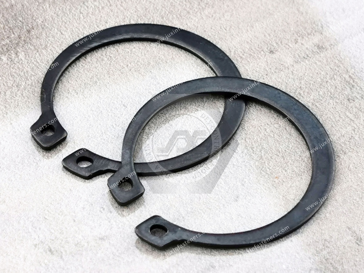
A circlip is a spring-type retaining element designed to engage a groove in a shaft or bore and restrict axial movement of an assembled component.
Depending on the design, a circlip may retain:
bearings
gears
pulleys
spacers
bushings
rollers
pins
shaft-mounted components
housing-mounted components
The circlip itself is only one part of the retaining system.
For a groove-mounted assembly:
Retained Component → Circlip → Groove → Shaft or Housing
The performance of the assembly therefore depends on more than the ring alone.
The easiest way to distinguish the two designs is by asking:
Where is the groove?
The groove is machined around the outside diameter of a shaft.
The external circlip fits around the shaft and engages that groove.
The groove is machined into the inside diameter of a bore or housing.
The internal circlip expands into that groove.
This gives us the basic engineering rule:
External = Shaft
Internal = Bore
That simple distinction prevents one of the most common mistakes in retaining-ring identification and sourcing.
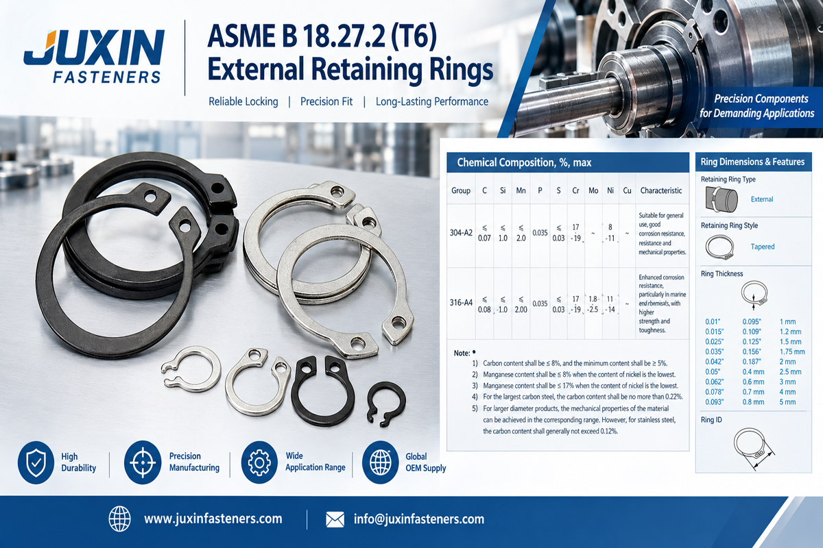
DIN 471 is associated with external retaining rings used on shafts.
A typical assembly may contain:
Shaft Shoulder → Bearing / Gear / Spacer → DIN 471 External Circlip
The ring provides an axial retaining boundary for the component.
DIN 471-style external circlips can be found in suitable assemblies involving:
electric motors
gearboxes
pumps
industrial machinery
automotive mechanisms
agricultural equipment
construction equipment
power tools
automation equipment
Actual suitability depends on the ring size, groove, loading and assembly requirements.
An external circlip is normally expanded during installation.
Suitable circlip pliers engage the installation holes or lugs and expand the ring sufficiently to pass over the shaft.
The ring is then positioned over the groove.
When installation force is released, the spring characteristics of the ring allow it to contract into the groove.
The ring should seat correctly in the designed groove before the assembly is placed into service.
DIN 472 is associated with internal retaining rings used inside bores or housings.
A typical assembly may contain:
Housing Shoulder → Bearing → DIN 472 Internal Circlip
The internal ring engages a groove in the bore and provides an axial retaining boundary.
Typical applications may include:
bearing housings
gear housings
electric motors
pumps
machinery
transmission assemblies
mechanical equipment
An internal circlip follows the opposite installation logic.
Instead of expanding around a shaft, it is normally compressed during installation.
The ring is reduced sufficiently to enter the bore and reach the groove.
When the installation force is released, the ring expands outward into the internal groove.
Therefore:
External Circlip → Expand for installation
Internal Circlip → Compress for installation
This distinction is important when selecting both the ring and the installation tool.
The two standards serve different assembly geometries.
| Design Question | DIN 471 | DIN 472 |
|---|---|---|
| Installation location | Shaft | Bore / housing |
| Ring type | External | Internal |
| Groove location | Outside of shaft | Inside of bore |
| Installation action | Ring expands | Ring compresses |
| Primary function | Axial shaft-component retention | Axial bore-component retention |
| Typical retained component | Gear, bearing, spacer | Bearing or housing-mounted component |
The exact dimensions and groove requirements should follow the applicable standard or controlled engineering drawing.
They may look similar in a photograph, but their geometry is engineered around opposite installation conditions.
An external ring must contract toward a shaft groove.
An internal ring must expand toward a bore groove.
This influences:
free-state diameter
lug geometry
spring behavior
installation method
groove relationship
load transfer
Therefore, selecting a circlip by visual similarity alone can result in the wrong component.
An E-ring is also used for shaft retention, but it is not the same design as a conventional DIN 471 external circlip.
Typically:
installed over the shaft
expanded using suitable circlip pliers
seated into an external groove
Typically:
installed radially from the side
engages a suitable shaft groove
does not need to pass over the end of the shaft
A widely recognized metric E-style retaining element is associated with DIN 6799.
This means the design decision is not simply:
“Do I need a retaining ring?”
It may instead be:
Shaft or Bore?
then:
Axial Installation or Radial Side Installation?
Assembly architecture can determine which retaining-ring design is practical.
Imagine a shaft where the end is blocked by another component.
A conventional external circlip may become difficult to install if the assembly sequence requires the ring to pass over the shaft.
A radially installed E-ring may be more suitable if the design supports that technology.
Conversely, another assembly may provide easy access to the shaft end and already contain a groove designed for a DIN 471-style external circlip.
Therefore:
Assembly Access → Retaining Ring Architecture
This decision should ideally be made during product design rather than after tooling is complete.
One of the most important engineering principles for retaining rings is:
The groove is not just a mounting detail. It is part of the retention system.
For an external circlip, the shaft groove interacts directly with the ring.
For an internal circlip, the bore groove performs the equivalent function.
Depending on the design, relevant characteristics can include:
groove diameter
groove width
groove position
edge geometry
surrounding material
distance to adjacent features
These dimensions should follow the applicable standard, manufacturer engineering data or validated customer drawing.
A common reverse-engineering mistake is to measure a loose circlip and then design a groove around those dimensions.
That approach ignores the intended installed condition.
The ring changes geometry during installation and engagement.
Therefore:
Free-State Ring Dimensions ≠ Groove Design Dimensions
Use the applicable standard or validated design data.
For a shaft-mounted system, axial force may follow approximately:
Retained Component → External Circlip → Shaft Groove → Shaft
This means several elements can influence the retention capability.
Potential limiting factors include:
ring deformation
ring failure
groove deformation
groove-edge failure
shaft material deformation
retained-component deformation
A stronger ring does not automatically solve a weak groove.
For a bore-mounted assembly, the path may be:
Retained Component → Internal Circlip → Bore Groove → Housing
Again, the ring is only one part of the system.
Housing material and groove geometry can influence the performance of the complete retention system.
This is particularly important when the housing material differs substantially from the retaining-ring material.
Circlips require material characteristics that allow controlled elastic deformation during installation and reliable engagement after assembly.
Common product families may include:
Spring steel is widely used for industrial retaining rings because the component must deform during installation and recover appropriately.
The exact material and heat-treatment requirements should follow the applicable product standard, drawing or customer specification.
Stainless steel may be selected where additional corrosion resistance is required.
The appropriate stainless grade should be defined according to the actual specification and service environment.
“Stainless steel” should not automatically be treated as one universal material grade.
Some applications may require other material systems based on:
temperature
corrosion
chemicals
magnetic requirements
equipment environment
customer specifications
Material substitution should be reviewed before approval.
A hardness value should not be applied universally across all circlip designs, sizes and materials.
The required mechanical properties can vary according to:
standard
material
ring size
manufacturing process
heat treatment
application
Therefore, procurement should source against the applicable standard or drawing rather than copying a generic HRC range from an unrelated product.
Depending on material and application, retaining rings may be supplied with different surface conditions or protective finishes.
Selection can depend on:
corrosion environment
appearance
storage conditions
mating materials
customer requirements
For OEM applications, the finish should be defined by specification rather than visual color alone.
These should not be treated as equivalent corrosion solutions.
May be used on suitable ferrous components as part of a defined finish system.
Its corrosion performance depends on the complete treatment and service environment.
May be used for suitable steel components depending on the specification and application.
Corrosion resistance comes primarily from the stainless material itself rather than an applied carbon-steel coating.
However, the actual performance depends on stainless grade and environment.
The correct choice should be based on the real service condition.
A corrosion-resistant retaining ring does not guarantee a corrosion-resistant assembly.
Also evaluate:
shaft or housing material
adjacent components
moisture
salt exposure
cleaning chemicals
process fluids
temperature
galvanic interaction where relevant
The best ring material is the one compatible with the complete assembly requirements.
“Anti-loosening” is sometimes used loosely in product descriptions, but it can create confusion.
A circlip's primary function is axial retention.
It should not automatically be described as a substitute for:
thread-locking systems
lock nuts
locking washers
prevailing-torque fasteners
torque-transmission features
For engineering content, the more precise term is:
Axial Retention
rather than a generic “anti-loosening” claim.
Not generally as their primary function.
If a component must be rotationally locked to a shaft, engineers may need:
keys
splines
pins
flats
interference fits
clamping systems
another torque-transfer feature
The circlip may retain the component axially while another feature controls rotation.
External circlips may be used in suitable shaft assemblies involving:
Potential retention of:
bearings
spacers
shaft-mounted components
Potential applications involving:
gears
bearings
spacers
shaft assemblies
Used in appropriate mechanical subassemblies requiring compact axial retention.
Potential applications include suitable:
shafts
linkages
actuator mechanisms
transmission-related assemblies
mechanical subassemblies
Circlips can provide compact axial retention in:
actuators
drive systems
machinery
robotic mechanical assemblies
The specific design must be validated for the actual application.
Internal circlips are particularly relevant where a component must be retained inside a cylindrical housing.
Examples can include:
bearing housings
motor housings
pump housings
gearbox housings
mechanical cylinders
equipment assemblies
A common design pattern is:
Housing Shoulder + Bearing + Internal Circlip
This can provide compact axial location without an additional threaded retaining component.
Automotive and transportation systems can place additional demands on retaining components through:
vibration
shock
corrosion
thermal cycling
high production volumes
OEM and Tier suppliers may therefore require controlled:
dimensions
material
heat treatment
finish
traceability
process capability
inspection
change management
The applicable customer drawing remains the primary product definition.
When a circlip retains a bearing or gear, engineers should consider more than nominal diameter.
Review:
expected axial load
shaft or bore material
groove geometry
assembly access
serviceability
operating speed of surrounding components
vibration
temperature
corrosion environment
The ring's purpose is axial retention, but its success depends on the surrounding design.
Correct installation tools help reduce component damage and improve assembly consistency.
External circlip pliers expand the ring for installation over a shaft.
Internal circlip pliers compress the ring for insertion into a bore.
E-style retaining rings may use dedicated radial installation equipment or production tooling.
For high-volume assembly, tool design and assembly automation can become part of the component-selection decision.
Over-expanding an external circlip can permanently alter its geometry.
Over-compressing an internal ring can also damage the component.
Using unsuitable tools may damage installation holes or distort the ring.
A ring that appears installed may not be fully seated.
A visually similar retaining ring may belong to another standard or size.
A correct ring cannot compensate for a damaged groove.
After installation, the ring should be inspected according to the assembly requirement.
Depending on the design, verify:
correct part
complete groove engagement
no obvious deformation
correct position
no installation damage
required clearance or component position
Where the application is safety- or reliability-sensitive, inspection criteria should be formally defined.
Reuse should not be assumed universally.
A previously installed ring may have experienced:
excessive expansion or compression
permanent deformation
wear
corrosion
surface damage
installation damage
Visual appearance alone may not establish whether the original mechanical behavior has been retained.
For OEM or maintenance applications, follow the approved service requirement.
When a retaining ring becomes disengaged, the ring itself is only one possible cause.
Investigate:
correct type?
correct size?
correct standard?
correct material?
correct diameter?
correct width?
damaged?
worn?
contaminated?
fully seated?
over-expanded?
over-compressed?
damaged during assembly?
unexpected axial load?
impact?
shock?
assembly change?
component contacting the ring incorrectly?
interference?
deformation?
Root-cause analysis should evaluate the entire retention system.
A simple engineering path is:
Where must the component be retained?
Evaluate an external retaining ring.
If the assembly is compatible with a conventional grooved shaft circlip, evaluate a DIN 471-type solution.
If radial side installation is preferable, evaluate an E-ring / DIN 6799-type solution where appropriate.
Evaluate an internal retaining ring.
For applicable metric designs, evaluate a DIN 472-type solution.
Then continue with:
Axial Load → Groove → Material → Finish → Installation → Validation
A purchasing request such as:
“10 mm circlip”
is incomplete because it does not tell the supplier whether the customer requires:
external ring
internal ring
E-ring
another retaining-ring design
A better standard-part RFQ includes:
standard
ring type
nominal size
material
finish
quantity
For example, the standard designation can immediately communicate much more technical information than the phrase “10 mm circlip.”
Provide:
standard designation
external or internal
nominal shaft or bore size
material
finish
quantity
annual demand
packaging requirements
documentation requirements
Provide:
2D drawing
dimensions
tolerances
material
heat-treatment requirements where specified
mechanical-property requirements where specified
finish
inspection requirements
sample quantity
production quantity
annual forecast
If the original supplier part number is obsolete or another source is required, provide:
original part number
original standard if known
drawing
physical sample
shaft or bore dimensions
groove dimensions
application
environment
annual usage
Do not assume a supplier can determine functional equivalence from a photograph alone.
Two circlips may appear dimensionally similar but differ in:
material
heat treatment
spring behavior
finish
groove requirements
standard
manufacturing tolerances
Therefore:
Appearance Match ≠ Standard Match
Dimensional Match ≠ Material Match
Material Match ≠ Functional Approval
For OEM second-source projects, these distinctions matter.
Standard DIN or other internationally recognized retaining-ring designs should normally be evaluated first where they meet the assembly requirement.
Custom retaining components may be appropriate when the project requires:
non-standard geometry
special installation architecture
unusual material
customer-specific spring characteristics
unique packaging space
special stamped features
integration with another function
A custom design should be driven by a defined engineering requirement.
For further engineering and sourcing information, review related resources on:
Shaft Retaining Rings Selection Guide
DIN 471 External Retaining Rings for Shafts
DIN 472 Internal Retaining Rings for Bores
DIN 6799 Retaining Washers for Shafts
E-Rings and E-Clips
JIS Retaining Washers for Shafts
Stainless Steel Retaining Rings
Spring Steel Retaining Rings
Custom Stamped Components
These pages can help engineers and procurement teams move from general technology selection to the specific retaining component required by the assembly.
JUXIN FASTENERS supplies standard and custom fastening components for industrial OEM and manufacturing applications.
Our retaining-component sourcing capabilities include:
external circlips
internal circlips
shaft retaining rings
bore retaining rings
E-rings
E-clips
DIN 471 retaining rings
DIN 472 retaining rings
DIN 6799 retaining washers
stainless steel retaining rings
spring steel retaining rings
custom stamped retaining components
For a standard component, send:
Standard → Type → Size → Material → Finish → Quantity → Annual Demand
For a drawing-controlled project, send:
Drawing → Dimensions → Tolerances → Material → Mechanical Requirements → Finish → Inspection → Quantity
For second-source or replacement sourcing, send:
Existing Part Number → Drawing / Sample → Shaft or Bore → Groove → Application → Annual Usage
JUXIN FASTENERS can support standard-part sourcing, drawing review, sample comparison and made-to-drawing retaining components for global industrial OEM and supply-chain projects.
Email: info@juxinfasteners.com
Website: www.juxinfasteners.com
 MORE NEWS

Sep. 27, 2026

Sep. 27, 2026

Sep. 27, 2026
Contact Us
Tel.:
+86 020 8621 0320
+86 020 3121 6067
E-mail:
Technical Support:
Navigation
SEND INQUIREY