
Call Us
+86 136 6007 9809
Call Us
+86 136 6007 9809

Oct. 24, 2023
Shaft retaining rings are compact mechanical fastening components used primarily to locate and retain components axially on shafts.
Depending on the assembly, they may retain components such as:
bearings
gears
pulleys
rollers
bushings
spacers
wheels
levers
pins
other shaft-mounted components
Unlike a conventional nut-and-thread arrangement, many retaining rings use spring action together with a machined groove or another designed retaining feature.
This can provide a compact and production-efficient method of axial retention.
However, “shaft retaining ring” describes a family of products rather than one universal design.
External circlips, E-rings, side-mount retaining rings and groove-free self-locking retainers operate differently and should not automatically be treated as interchangeable.
For engineers and procurement teams, selection should begin with:
Shaft → Retained Component → Axial Load → Groove / No Groove → Available Space → Ring Type → Material → Environment → Assembly Method → Validation
A shaft retaining ring is a mechanical retaining element installed on or around a shaft to restrict axial movement of another component.
A common groove-mounted arrangement can be represented as:
Shaft Shoulder / Component / Retaining Ring
or
Retaining Ring / Component / Retaining Ring
depending on the assembly design.
The retaining ring typically engages a groove in the shaft. The retained component transfers axial load toward the ring, and the ring transfers that load into the groove.
This creates an important engineering distinction:
The retaining ring is part of a retention system.
Its performance cannot be evaluated independently from the shaft, groove and retained component.
A shaft retaining ring is primarily an axial retention component.
It should not automatically be specified as a torque-transmitting or anti-rotation device.
If the assembly must prevent relative rotation or transmit torque, engineers may need to evaluate other features such as:
keys
splines
flats
pins
clamping features
interference fits
other torque-transmission designs
A retaining ring may coexist with these features, but its primary role remains axial positioning or retention.
For a typical external retaining ring, the shaft contains a machined groove.
The ring is expanded during installation, positioned over the shaft and seated into the groove.
After installation, the ring's spring characteristics help it remain engaged with the groove.
When an axial force acts on the retained component, load is transferred through the assembly into the retaining ring and shaft groove.
Therefore, retention depends on the complete interface:
Ring Geometry + Groove Geometry + Shaft Material + Retained Component + Axial Load + Installation
This is why ring selection cannot be based only on shaft diameter.
Several retaining technologies are used on shafts. Their geometry, installation method and application logic differ.
External retaining rings are installed into grooves on shafts.
A widely recognized metric design is associated with DIN 471 retaining rings for shafts.
These components typically have installation lugs or holes that allow suitable retaining-ring pliers to expand the ring during assembly.
Common applications include:
shafts
gear assemblies
bearings
electric motors
pumps
transmissions
industrial machinery
An external circlip may be appropriate when:
a shaft groove can be machined
axial retention is required
radial installation space is available
assembly and service access permit installation
the ring and groove can be engineered for the required load
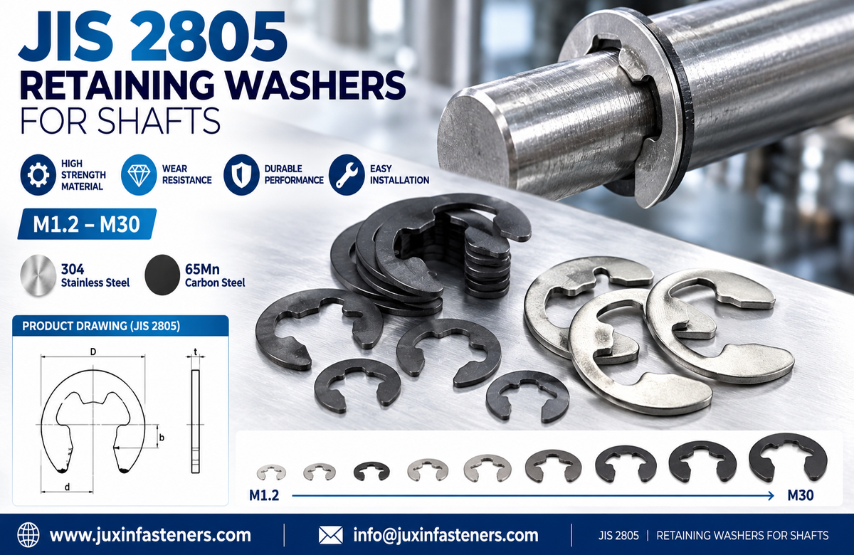
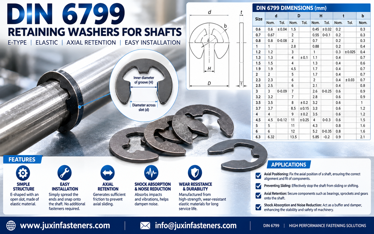
E-rings have a distinctive E-shaped geometry and are generally installed radially from the side of the shaft.
This can provide an assembly advantage because the component does not necessarily need to be installed over the end of a long shaft.
A widely recognized metric reference for this type of retaining element is DIN 6799.
Typical applications can include:
small shafts
pins
linkage assemblies
mechanisms
appliances
automotive components
compact mechanical assemblies
Potential design advantages include:
side installation
compact axial packaging
suitability for automated or high-volume assembly
no need to slide the ring over the complete shaft length
However, the groove and ring must still be selected as a compatible system.
“Side-mount” describes retaining elements that can be installed radially rather than axially over the end of the shaft.
E-style rings are a common example, but other retaining geometries may also use side installation.
This can be useful when:
the shaft end is inaccessible
another component blocks axial installation
production requires rapid radial assembly
assembly sequence favors side access
Installation method is therefore an important part of product selection.
Some external retaining-ring designs use an inverted lug configuration to modify the external profile around the shaft.
They may be considered where surrounding component clearance or assembly geometry makes a conventional lug configuration undesirable.
Engineers should verify the applicable product specification and groove requirements rather than assuming an inverted ring is dimensionally interchangeable with a conventional external circlip.
Some applications require retaining elements with geometry designed for higher axial-load demands.
However, “heavy duty” should not be interpreted as a universal load rating.
Actual capacity depends on factors including:
ring geometry
ring material
groove geometry
shaft material
shaft diameter
load direction
installation condition
The required assembly should be evaluated against the applicable engineering data.
Some retaining elements are designed for installation on shafts without a conventional machined groove.
These may use spring features or teeth to engage the shaft surface.
They can be useful where:
groove machining is undesirable
assembly cost must be minimized
the application is suitable for this retaining mechanism
installation is intended to be fast
However:
Groove-Free ≠ Equivalent to Groove-Mounted
A self-locking retaining element and a DIN 471-style external circlip use different retention mechanisms.
They should not be substituted without engineering review.
One of the most useful early design decisions is determining how the ring must be installed.
Typically:
installed over the shaft
seated into an external groove
expanded during installation
commonly installed using circlip pliers
Typically:
installed radially from the side
engages a suitable shaft groove
does not need to travel over the shaft end
can be attractive for high-volume assembly
Therefore:
External Circlip → Axial access to the shaft is normally important
E-Ring → Radial side access may simplify assembly
This difference can influence product architecture and assembly-line design.
Another fundamental choice is whether the shaft will contain a groove.
Advantages may include:
positive geometric engagement
controlled axial location
established standardized product families
repeatable assembly position
But the shaft requires the correct groove.
Potential advantages include:
reduced shaft machining
simplified assembly in suitable applications
But retention depends on a different engagement mechanism.
The choice should be made during mechanical design rather than after the shaft geometry has already been finalized.
A sourcing request such as:
“Need 10 mm retaining ring”
may not provide enough information.
For a groove-mounted retaining ring, engineers and suppliers may need to understand:
shaft nominal diameter
groove diameter
groove width
groove position
retained component geometry
axial load
surrounding clearance
material
finish
assembly method
Two retaining components associated with the same nominal shaft size may have different geometries and installation requirements.
For groove-mounted retaining rings, the groove is part of the fastening system.
Important characteristics can include:
groove diameter
groove width
groove position
edge geometry
shaft material
distance to shaft end or adjacent features
relationship to the retained component
The correct values should come from the applicable retaining-ring standard, manufacturer engineering data or validated customer design.
Do not create groove dimensions by measuring only the free-state retaining ring.
If the groove does not correctly interface with the ring, potential problems can include:
excessive axial movement
poor seating
unintended ring deformation
difficult assembly
compromised retention
The groove should therefore be controlled as an engineering feature of the shaft.
Groove diameter affects how the retaining ring engages the shaft.
An incorrectly designed groove can alter:
ring seating
stress in the ring
axial support
installation behavior
This is another reason why a retaining ring should not be selected solely from its outside dimensions.
In a groove-mounted shaft-retaining assembly, axial load follows a path approximately like:
Retained Component → Retaining Ring → Groove → Shaft
This means that failure can originate from more than the ring itself.
Potential limiting factors may include:
ring deformation
ring failure
groove deformation
groove-edge failure
shaft material yielding
retained component deformation
incorrect installation
The system should therefore be evaluated as an assembly.
Material selection depends on the application, mechanical requirements and environment.
Common categories can include:
Spring steel is widely used for retaining rings because the component must elastically deform during installation and recover sufficiently to perform its retaining function.
Depending on the application, an appropriate surface finish may also be specified.
Stainless steel retaining rings may be considered where corrosion resistance is important.
The specific stainless grade should be defined by the applicable specification or customer requirement.
“Stainless steel” alone should not automatically be treated as a complete material specification for controlled OEM programs.
Some specialized retaining components may use other metals or engineered materials.
Suitability should be evaluated against:
mechanical load
temperature
environment
chemical exposure
assembly requirements
service life
Depending on material and application, retaining rings may be supplied with finishes intended for:
corrosion protection
handling
appearance
application-specific requirements
Possible finishes depend on the actual product and specification.
For OEM sourcing, procurement should define the required finish rather than purchasing only by visual color.
Selecting stainless steel or a coated spring-steel retaining ring does not by itself establish the corrosion performance of the complete assembly.
Engineers should also consider:
shaft material
adjacent component material
moisture
salt exposure
chemicals
temperature
galvanic interaction where relevant
Material selection should match the real service environment.
Retaining rings can be found in suitable automotive mechanical assemblies involving:
shafts
pins
linkages
actuators
rotating assemblies
transmission-related mechanisms
seating or adjustment mechanisms
other mechanical subsystems
The specific ring type depends on the vehicle system and engineering specification.
For automotive OEM and Tier suppliers, additional requirements may include:
controlled material
dimensional capability
surface treatment
traceability
production consistency
application-specific validation
Retaining rings can provide compact axial retention for components such as:
bearings
gears
spacers
shaft-mounted components
In these systems, engineers should consider:
axial loading
rotational environment
assembly clearance
groove geometry
maintenance requirements
The ring retains components axially; it should not automatically be treated as the feature transmitting shaft torque.
Pumps and industrial equipment may use shaft retaining rings in mechanical subassemblies where compact axial positioning is required.
Potential engineering considerations include:
vibration
corrosion
maintenance access
temperature
axial loading
surrounding component clearance
Product selection should follow the actual assembly conditions.
E-rings and other compact retaining elements can be useful in:
power tools
actuators
small mechanisms
appliance assemblies
compact gear systems
Radial installation can be particularly useful where production speed and limited axial access influence assembly design.
Retaining elements may also be used in:
linkage mechanisms
control assemblies
pins
shafts
equipment subassemblies
Outdoor equipment can introduce additional considerations such as:
dirt
moisture
corrosion
shock
vibration
The material and finish should therefore be selected for the actual service environment.
Reuse should not be assumed simply because a ring can be removed.
During removal and previous service, a retaining ring may experience:
permanent deformation
excessive expansion
wear
corrosion
installation damage
loss of required spring behavior
For controlled assemblies, follow the OEM maintenance requirement or applicable engineering specification.
Where reliability is important, replacement during service may be required.
The groove and assembly conditions also matter.
External rings are designed for shafts.
Internal rings are designed for bores or housings.
Their geometries and installation methods differ.
Both can retain components on shafts, but their geometry and installation method differ.
The groove is part of the retention system.
Axial retention and torque transmission are different engineering functions.
Corrosion, spring properties and service environment should also be considered.
Removal may alter the component.
Similar-looking components may follow different standards, dimensions or material requirements.
If a retaining ring leaves its groove, deforms or fails during service, replacing it with a stronger-looking ring is not automatically the correct solution.
Investigate:
correct part?
correct material?
deformation?
corrosion?
installation damage?
correct diameter?
correct width?
damaged edges?
wear?
deformation?
correct material?
dimensional conformity?
damage?
excessive axial load?
unexpected impact?
incorrect installation?
surrounding interference?
operating conditions changed?
vibration or shock different from the original design?
incorrect replacement component installed?
This root-cause approach helps prevent repeated failures.
Depending on the drawing and quality plan, inspection may include:
dimensions
thickness
ring geometry
material
hardness or mechanical requirements where specified
finish
visual condition
burr control
packaging
lot identification
For high-volume OEM supply, process consistency can be as important as inspection of individual parts.
For standard components, provide:
standard designation
ring type
nominal shaft size
material
finish
quantity
annual usage
documentation requirements
For a drawing-controlled component, provide:
2D drawing
dimensions and tolerances
material
hardness or mechanical requirement where applicable
surface treatment
inspection requirements
sample quantity
production quantity
annual forecast
For an existing part without a drawing, provide:
physical sample
shaft diameter
groove dimensions if available
application photographs
material information
operating environment
quantity
A standard retaining ring should normally be evaluated first when the assembly can use an established standard geometry.
A custom component may be appropriate when the project requires:
non-standard shaft geometry
special profile
unusual installation method
special material
controlled spring characteristics
unique packaging constraints
integration with another mechanical function
Custom design should solve an actual assembly requirement rather than replace an available standard without technical reason.
A practical engineering sequence is:
Shaft or Bore?
↓
Shaft → External Retaining Technology
↓
Groove or No Groove?
↓
Axial Installation or Radial Side Installation?
↓
External Circlip / E-Ring / Other Retainer
↓
Define Axial Load
↓
Define Groove & Surrounding Geometry
↓
Select Material & Finish
↓
Confirm Assembly Method
↓
Prototype / Validate
↓
Production
This approach is more reliable than starting from a product photograph.
Engineers and procurement teams evaluating shaft retention systems may also review:
DIN 471 External Retaining Rings for Shafts
DIN 6799 Retaining Washers for Shafts
JIS Retaining Washers for Shafts
E-Clips and E-Rings for Industrial Assemblies
Stainless Steel Retaining Rings
Spring Steel Retaining Rings
Custom Stamped Components
Custom Industrial Fasteners
These pages can help compare standardized and drawing-controlled shaft-retention options.
JUXIN FASTENERS supplies standard and custom fastening components for industrial OEM and manufacturing applications.
For shaft retaining projects, we can support sourcing based on:
international standard
customer drawing
existing part number
physical sample
application requirements
Relevant product categories include:
external retaining rings
shaft circlips
E-rings
E-clips
DIN 471 retaining rings
DIN 6799 retaining washers
stainless steel retaining rings
spring steel retaining rings
custom stamped retaining components
For a standard part RFQ, send:
Standard → Size → Material → Finish → Quantity → Annual Demand
For a drawing-controlled component, send:
Drawing → Dimensions → Tolerances → Material → Finish → Quantity → Inspection Requirements
For an existing component requiring supplier development or replacement sourcing, send:
Existing Part Number → Drawing / Sample → Shaft & Groove Information → Application → Annual Usage
JUXIN FASTENERS can support drawing review, sample comparison, standard retaining components and made-to-drawing fastening projects for global industrial customers.
Email: info@juxinfasteners.com
Website: www.juxinfasteners.com
 MORE NEWS

Sep. 27, 2026

Sep. 27, 2026

Sep. 27, 2026
Contact Us
Tel.:
+86 020 8621 0320
+86 020 3121 6067
E-mail:
Technical Support:
Navigation
SEND INQUIREY